Article

Electrodeposited CoFeNi Medium-Entropy Alloy Coating on a Copper Substrate from Chlorides Solution with Enhanced Corrosion Resistance

1
Department of Engineering Processes Automation and Integrated Manufacturing Systems, Silesian University of Technology, Konarskiego 18a St., 44-100 Gliwice, Poland
2
Department of Engineering Materials and Biomaterials, Silesian University of Technology, Konarskiego 18a St., 44-100 Gliwice, Poland
3
Materials Research Laboratory, Faculty of Mechanical Engineering, Silesian University of Technology, Konarskiego 18a St., 44-100 Gliwice, Poland
4
Institute of Metallurgy and Materials Science, Polish Academy of Sciences, 25 Reymonta St., 30-059 Kraków, Poland
*
Author to whom correspondence should be addressed.
Coatings 2025, 15(5), 509; https://doi.org/10.3390/coatings15050509
Submission received: 28 February 2025 / Revised: 6 April 2025 / Accepted: 18 April 2025 / Published: 24 April 2025
(This article belongs to the Special Issue Advances of Ceramic and Alloy Coatings, 2nd Edition)

Abstract

:
Medium-entropy alloys (MEAs) exhibit properties comparable or even superior to high-entropy alloys (HEAs). Due to their very good resistance in thermomechanical conditions and corrosive environments and unique electrical and magnetic properties, medium-entropy alloys are good candidates for coating applications. One of the most economically effective methods of producing metallic coatings is electrodeposition. In this work, the structure of an electrodeposited CoFeNi medium-entropy alloy coating on a copper substrate from a metal chlorides solution (FeCl2 ∙ 4H2O + CoCl2 ∙ 6H2O + NiCl2 ∙ 6H2O) with the addition of boric acid (H3BO3) was investigated. The coating was characterized by a nanocrystalline structure identified by transmission electron microscopy examination and X-ray diffraction methods. Based on XRD and TEM, the face-centered cubic (FCC) phase of the CoFeNi MEA coating was identified. The high corrosion resistance of the MEA coating in a 3.5% NaCl environment at 25 °C was confirmed by electrochemical tests.

1. Introduction

In the past two decades, the scientific community has directed great interest toward multicomponent engineering materials, which are high-entropy alloys (HEAs). HEAs consist of five or more elements (each in the composition range of 5–35 at.%) and are characterized by high configurational entropy (typically ∆S > 1.5 R, where R is the gas constant). Alloys containing at least 3–4 elements with equal atomic fractions or configurational entropy ranging from 1 R to 1.5 R are classified as medium-entropy alloys (MEAs) [1,2]. MEAs derived from the CoCrFeNiMn (Cantor alloy) system are distinguished into ternary (CoFeNi, CoCrFe, CoCrMn, CoCrNi, CoFeMn, CoNiMn, CrFeMn, CrFeNi, CrNiMn, FeNiMn) and quaternary (CrFeNiMn, CoFeNiMn, CoCrNiMn, CoCrFeMn, CoCrFeNi) alloys [1]. HEAs and MEAs can be classified as modern materials of the future that fit into the Sustainable Development Goals [3]. So far, a number of high- and medium-entropy alloy systems have been developed and studied in detail. MEAs exhibit unique, very specific combinations of physical and chemical properties and, consequently, have great application potential in various industries. However, despite their lower configurational entropy, some MEAs have properties comparable to or even superior to HEAs [2,4,5,6]. For example, better properties of CrCoNi MEA compared to Cantor’s alloy (CrMnFeCoNi) and most modern engineering alloys have been explained by the formation of a continuous sequence of strengthening mechanisms based on hierarchical twin networks [1]. On the other hand, a large number of MEAs, due to the reduced phase stability resulting from lower entropy, can form multiphase structures exhibiting a complex effect of soft and hard phases [7].
MEAs with excellent mechanical properties can find applications in aerospace, automotive, power generation, and biomedicine, among others [8,9,10]. For example, the ternary CoCrNi alloy had a higher hardness than other alloys tested and showed excellent results in the dynamic shear test and impact fracture resistance [5]. NiCoFe medium-entropy alloy exhibits exceptional thermomechanical properties for use in extreme environmental conditions [11] and good corrosion resistance [12]. In turn, the electrodeposited equiatomic nanocrystalline FeCoNi MEA achieved a maximum tensile strength of 1.6 GPa [13], while Fe-rich FeCoNi showed a tensile strength of 1.2 GPa and an elongation at break of 6.3% [14].
These materials can be obtained using a variety of techniques, including solid-state synthesis (mechanical alloying (MA) and spark plasma sintering (SPS)) and liquid synthesis (arc melting, ball milling, and laser deposition), as well as gas-phase methods, including atomic layer deposition (ALD) and molecular beam epitaxy (MBE) [15]. As functional and structural materials, HEA/MEA coatings are widely used, with high hardness, strength, and resistance to cracking, as well as resistance to corrosion and high-temperature oxidation. In addition, they exhibit unique electrical and magnetic properties. They can be produced on the surface of matrix materials using methods such as laser cladding, thermal spraying, magnetron sputtering, plasma arc cladding, and electrodeposition [16,17,18,19,20]. Among these techniques for producing alloy coatings, electrodeposition is most often used for economic reasons, as it consumes less energy than solid-state and laser processes. Apart from the limitations of the toxicity of some elements and the impossibility of electroplating all metals, the undoubted advantage of this technique is its simplicity and the possibility of accurate control of the thickness and composition of the coating [9,21]. It is possible to successfully deposit coatings using two electrodeposition technologies, namely direct current (DC) and pulsed current (PC); however, the coating produced by the PC method was shown to have better corrosion resistance in a 3.5% NaCl solution than the coating obtained by the DC method at the same deposition current density [22]. On the other hand, in work [23], pulse electrodeposition allowed an almost equiatomic nanocrystalline FeCoNi medium-entropy alloy to be obtained, whose tensile strength was 1598 MPa and maximum elongation at room temperature was 3.43%. An important component in the electrodeposition process is the composition of the bath, as well as the substrate on which the coatings are deposited. The successful electrodeposition of high/medium-entropy alloys depends on a well-selected electrolyte, which influences the structure and properties of the alloy. Among the various types of baths, aqueous, ionic, and organic electrolytic baths are most often used for HEA/MEA deposition. The ionic and organic ones are expensive, although the advantage of the ionic ones is the release of a small amount of hydrogen during electrodeposition [24]. Water baths are environmentally friendly, easily accessible, and safe to use. Moreover, by adjusting the concentration of metal salts or using specific additives, it is possible to design the properties of the deposited coatings. In order to achieve the desired composition and structure of electrodeposited HEA/MEA coatings, it is necessary to precisely control deposition parameters such as the deposition current density, temperature, and pH of the bath, as well as deposition time, which affect the growth kinetics, crystallographic orientation, and grain size of the coatings. The most important parameter that significantly affects the composition, morphology, and mechanical properties of the coating is the current density [25]. As shown in [26], the use of lower current densities allows coatings with a smooth surface to be obtained, while increasing the current density causes the occurrence of microcracks in the coatings. Also, in work [24], it was demonstrated that a homogeneous and compact coating of a multicomponent NiFeCoCu alloy with favorable anti-corrosion properties was obtained at a current density in the range of 20–40 mA/cm2. As the current density increased to 60 mA/cm2, the surface roughness of the coatings increased. In turn, the influence of different current densities on the microstructure of CoNiFe MEA was studied in work [27]. The coatings obtained at a low current density of 44.4 A/dm2 showed almost equimolar ternary components with a face-centered cubic (FCC) structure. The coatings obtained at higher current densities of 66.7 A/dm2 and 88.9 A/dm2, respectively, showed two FCC phases with different chemical compositions, while at a current density of 111.1 A/dm2, the coating consisted exclusively of the Ni-rich phase. In electrodeposited MEAs, BCC (body-centered cubic) and FCC+BCC structures can also be formed [28]. Some coatings can obtain an amorphous or nanocrystalline structure [29].
In this paper, CoFeNi medium-entropy alloy coatings were deposited on a copper substrate from a metal chlorides solution by direct current. The aim of the studies was to carry out thorough structural investigations, especially since most of the results in the literature focus on sulfate environments. Corrosion resistance measurements were also carried out to assess the utility properties of electrodeposited MEA coatings.

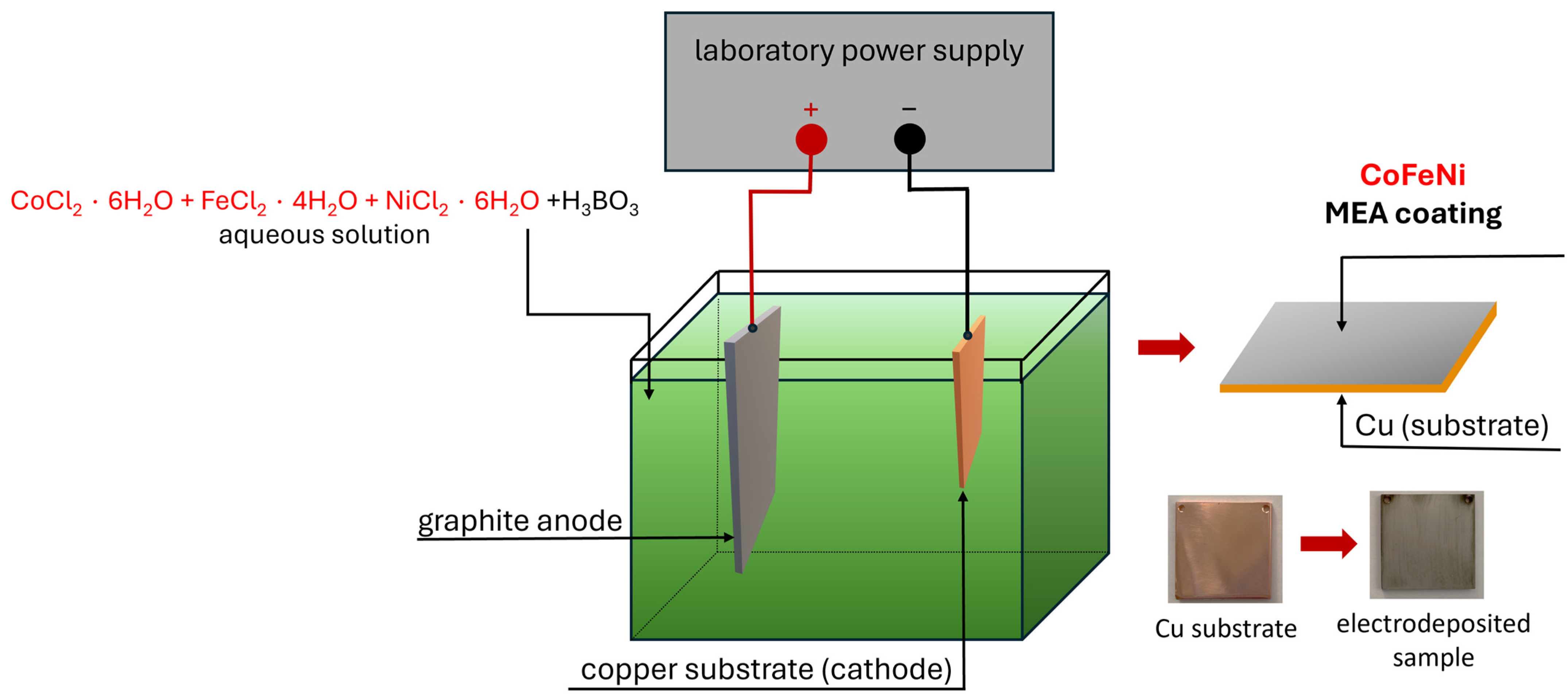
2. Materials and Methods

Copper plates measuring 50 × 50 × 0.5 mm were degreased in a solution of NaOH (25 g/L), Na2CO3 (25 g/L), and Na3PO4 (25 g/L) and then etched in a solution of H2SO4 (100 mL/L), HNO3 (30 mL/L), and HCl (10 mL/L). Each time after degreasing and etching, the plates were rinsed in distilled water. The electrodeposition bath was an aqueous solution of FeCl2 ∙ 4H2O (8.11 g/L), CoCl2 ∙ 6H2O (7138 g/L), NiCl2 ∙ 6H2O (14,262 g/L), and H3BO3 (15 g/L). The hydrated chlorides were weighed in the indicated proportions on a laboratory scale and then mixed with 1 L of distilled water. Then, boric acid was added to stabilize pH and prevent oxidation of iron (II) chloride. The solution was stirred for 30 min using a magnetic stirrer. The pH of the electrodeposition bath was approximately 4 ÷ 5. The electrodeposition process was carried out at a current of 0.5 A for 30 min at a temperature of about 30 °C. The description of the influence of current and time will be presented in another publication. The PPH-1503 (GW Instek, New Taipei, Taiwan) was used as a power supply in the process. A graphite anode with dimensions of 120 × 44 × 4 mm was used in the electrodeposition. The scheme of the electrodeposition station is illustrated in Figure 1.
Structural investigations were carried out using X-ray diffraction (XRD), scanning electron microscopy (SEM), and transmission electron microscopy (TEM). Phase identification was performed based on XRD patterns recorded using a D8 Discover diffractometer (Bruker, Karlsruhe, Germany) (Co Kα, λ = 1.79 Å). The X-ray diffraction measurements were performed using the Bragg–Brentano scan. The crystallite size was evaluated using the Williamson–Hall (W–H) plot performed in the HighScore Plus program. The observations of the surface of the MEA coating were carried out using a Phenom ProX (Phenom World BV, Eindhoven, The Netherlands) scanning electron microscope. Moreover, the copper plate with the electrodeposited coating was mounted crosswise and subjected to grinding and polishing for cross-sectional observations. For both the observation of the surface of the applied coating and the cross-section, chemical composition distribution maps were recorded using the EDX method. Transmission electron microscopy studies were carried out on thin foil prepared using the focused ion beam milling method. TEM observations were performed using a Cs-corrected S/TEM TITAN 80–300 (FEI Company, Hillsboro, OR, USA) microscope in high-resolution mode (HRTEM). EDX chemical composition analysis was performed in STEM mode. Selected area diffraction (SAED) patterns were collected to identify the phase composition of the studied MEA coating.
SEM observations and atomic force microscope (AFM) surface topography analysis were also performed on the copper substrate after degreasing and etching. AFM studies in contact mode were performed using XE-100 (Park System, Suwon, Republic of Korea). Surface roughness (Ra) and analysis of the AFM results were performed using XEI 1.7.6 software (Park System, Suwon, Republic of Korea).
In order to investigate the corrosion resistance of the studied coating, electrochemical tests were carried out using the potentiodynamic method in 3.5% sodium chloride aqueous solution at 25 °C. The copper substrate was also tested for comparison and to confirm that the CoFeNi MEA coating was tight. The polarization plots were recorded after obtaining the curves of open-circuit potential (EOCP) changes as a function of time (1800 s). The time of the EOCP was determined based on the work of Huo et al. [27], where, before recording the polarization curves, the open-circuit potential as a function of time was measured for 1800 s. The test station consisted of an Autolab 302N potentiostat, a corrosion cell, and a system of three electrodes: a saturated calomel electrode (SCE) as the reference electrode, a platinum rod as the counter electrode, and the studied sample. The measurements were collected and analyzed using NOVA 1.11 software.

3. Results

3.1. X-Ray Diffraction

Figure 2 shows the diffraction pattern for the CoFeNi MEA coating electrolytically deposited on a copper substrate. The Cu from the substrate and face-centered cubic (FCC) phase reflections were identified. As we can see in the enlarged part of the XRD pattern shown in Figure 2, the peaks belonging to the FCC phase were small and wide, indicating a nanocrystalline structure. The crystallite size determined by the Williamson–Hall (W–H) method was 15 nm. It can be stated that according to the definition, the CoFeNi MEA coating had a nanocrystalline structure. Nanocrystalline alloys are single- or multi-phase polycrystalline solids with a grain size of 1 to 100 nm in at least one dimension [30]. The peaks of the Cu substrate were sharp. Multicomponent alloys, which include HEAs and MEAs, exhibit effects that result from interactions between the constituent elements, including high entropy and severe lattice distortion. The high entropy effect is the formation of disordered solid solutions with a correspondingly high entropy, while the severe lattice distortion effect results from the presence of many alloying elements creating an atomic size mismatch. These effects in HEAs and MEAs have a significant impact on the thermodynamic stability, microstructure, and mechanical properties [31]. Meng et al. [32] described the structure of the CoFeNi2 alloy arc-melted in a water-cooled copper crucible under an argon atmosphere as a single-phase FCC. Milyaev et al. [33], in their work, presented the results of research on Co-rich ternary alloys used in giant magnetoresistance multilayers. The X-ray diffraction studies confirmed that all CoFeNi initial alloys were characterized by the FCC solid solution structure, except for the Co70Fe25Ni5 alloy, which was characterized by a structure consisting of BCC and FCC phases. It should be emphasized that the reflections of the identified FCC phase showed similar values of the 2θ angle, as in the case of this work [33]. In the case of electrodeposited MEAs coatings (f.e. CoFeNi, CoNiCu), a structure consisting of a solid solution of FCC was also identified [27,29,34]. Huo et al. [27] also deposited CoFeNi MEAs on a copper substrate at room temperature with a graphite anode; however, they used sulfates and organic additives in the electrolytic bath and varying current density, i.e., 44.4 A/dm2, 66.7 A/dm2, 88.9 A/dm2, and 111.1 A/dm2. The structure of all the coatings studied showed face-centered cubic structures. Reflections from the copper substrate were also identified [27]. Watanabe et al. [13], also using an environment of sulfates and other additives in the form of inorganic and organic compounds influencing the quality of the coating, synthesized nanocrystalline FeCoNi MEA using a long deposition time (50 h). The authors [13] used XRD to identify the FCC phase, the occurrence of which was confirmed by TEM diffraction.

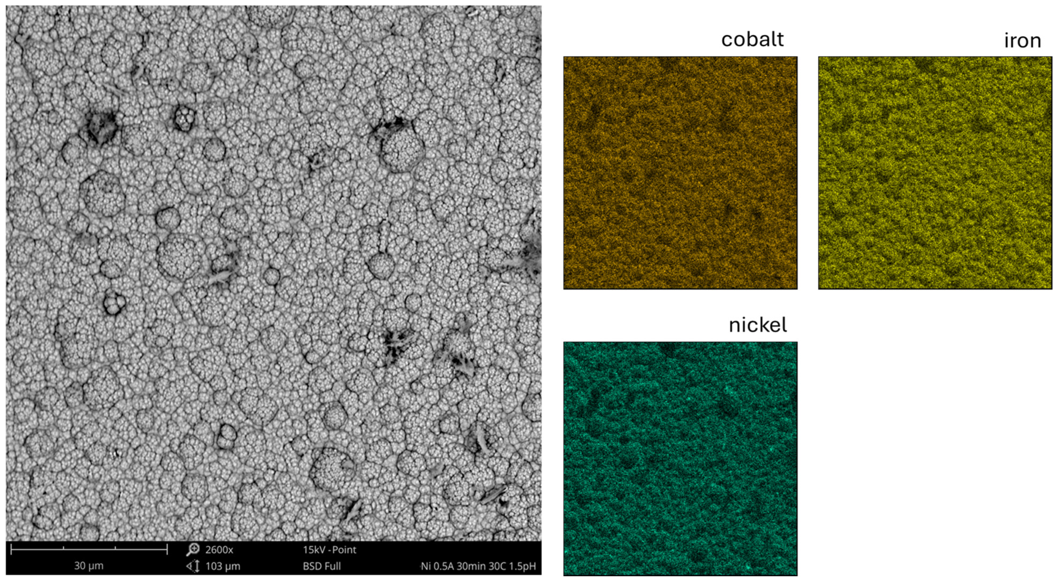
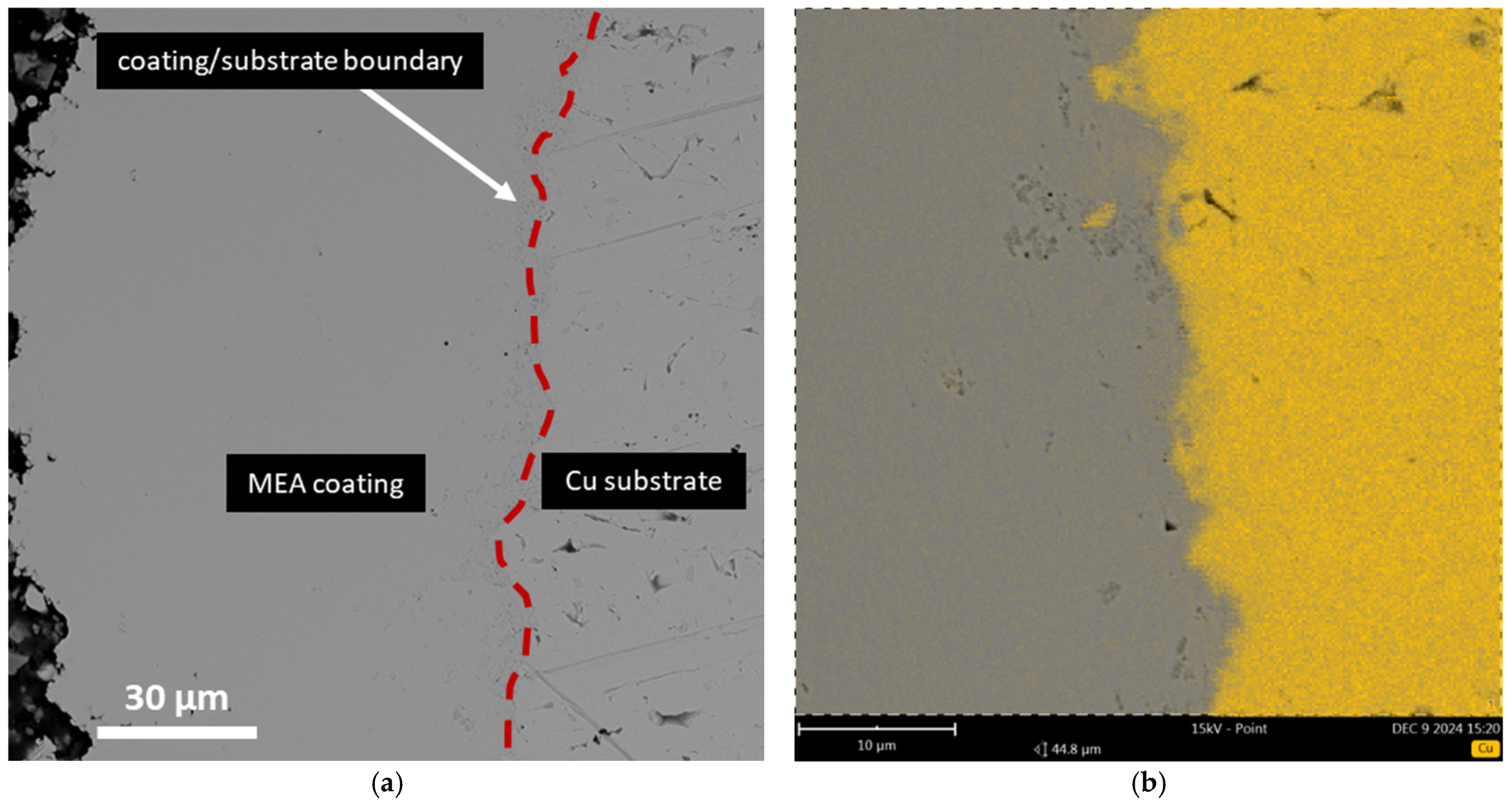
3.2. Scanning Electron and Atomic Force Microscopy

Figure 3 shows the SEM image along with EDX maps of the chemical element distribution of the surface of the CoFeNi coating electrodeposited on a copper substrate. Based on the analysis of the studied area, 37.6 at.% cobalt, 33.1 at.% nickel, and 29.3 at.% iron were identified. The SEM image shows a grainy morphology, typical for electrodeposited coatings. Huo et al. [27], for CoFeNi MEA coatings deposited from sulfate baths with the addition of boric acid and organic compounds, also presented SEM surface images. The morphology of the coatings was also grainy; however, cracks were visible, especially for the applied current density of 66.7 A/dm2 and 88.9 A/dm2. In the case of the coating described in this work, it can be observed that it was more compact [27].
Figure 4 shows the SEM image of the cross-section and EDX analysis of the copper distribution of the studied sample with the CoFeNi MEA coating on the copper substrate after grinding and polishing. The cross-section shows the boundary between the electrodeposited coating and the copper substrate (Figure 4a). Based on the copper distribution (Figure 4b), it can be observed that the substrate was characterized by a developed surface topography. The surface topography of the copper substrate was analyzed by SEM observations and AFM studies of the selected area (20 × 20 µm) after degreasing and etching. The results of the topography studies are shown in Figure 5. The copper substrate surface shows irregular pits after etching. Comparing the SEM image in Figure 5a with the cross-section of the coated sample in Figure 4, it can be concluded that the pits were conducive to the deposition of the coating in their free spaces. The 3D AFM surface topography map (Figure 5b) also indicates a developed surface. From the selected area of the AFM map, the surface roughness (Ra) of 72.1 nm was determined. However, in the literature [35], for Ni-Co-Fe coatings, higher roughness (0.1, 0.4, 0.7, and 1.1 µm) was obtained for copper substrates after grinding, without degreasing and etching. For the studied coating, the substrate was degreased and etched without prior grinding. According to the authors [35], the highest bond strength between the copper substrate and the Ni–Co–Fe coating was obtained for Ra 0.4 µm, while the lowest was obtained for Ra 1.1 µm. Moreover, Kong et al. [35] indicated a tendency for smaller roughness values of substrates on which Ni-Co-Fe coatings were deposited to have better corrosion resistance. There are works in which it was shown that the higher the surface roughness, the worse the adhesion of deposited coatings [36,37]. Based on the results described in this work, it can be concluded that the chemical etching of copper in a solution of H2SO4 + HNO3 + HCl allows the attainment of lower roughness than in the case of grinding. In the future, it is necessary to conduct studies on the adhesion of coatings and the effect of the chemical composition of the solutions and time during the etching process. Publication [38] describes the influence of the chemical compositions of the copper etching solutions used on the surface morphology. Among others, it was assessed that the HNO3 + H2SO4 solution used for etching effectively smoothed the surface of electroplated copper. However, the highest surface roughness for electroplated copper was noted in the case of using the FeCl3 + HCl solution [38].

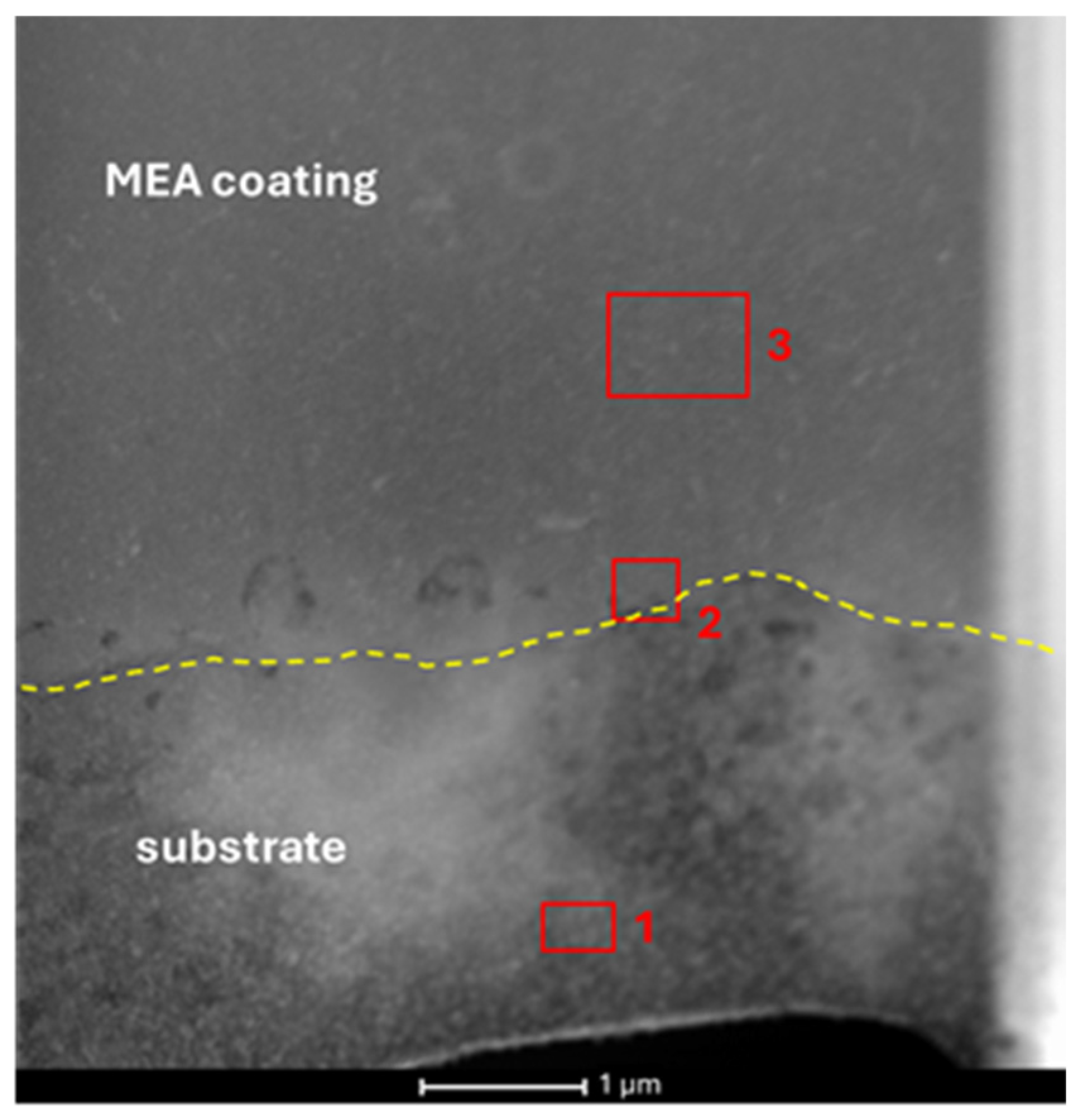
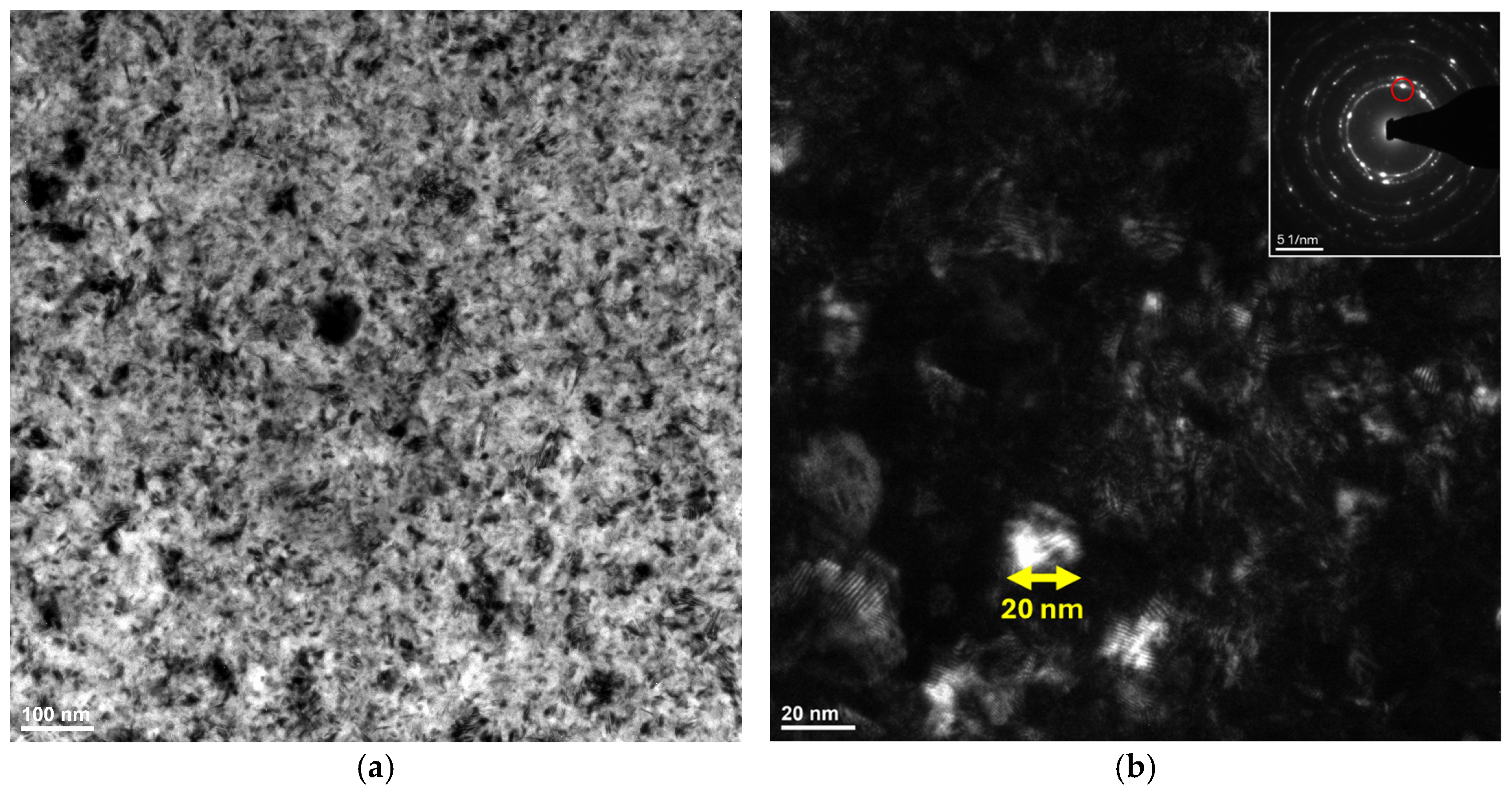
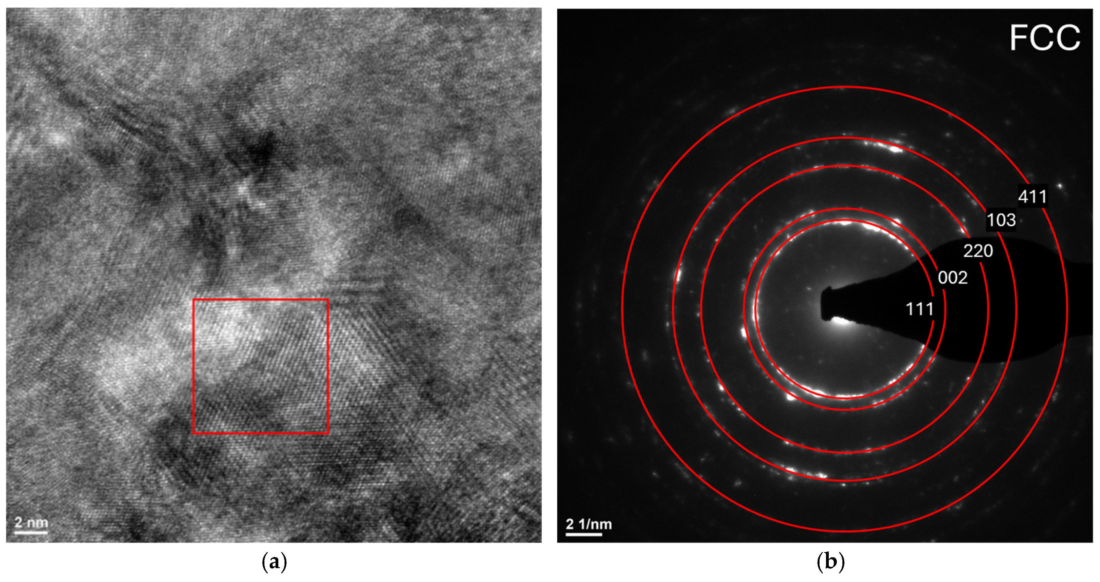
3.3. Transmission Electron Microscopy

Based on the analysis of the chemical composition using the EDX method, it was found that the electrodeposition process was of a diffusion nature due to the identification of copper in the areas of the coating. Figure 6 shows the HAADF STEM image with the areas for EDX analysis marked. Table 1 presents the atomic shares of individual elements for the areas marked in Figure 6. Area 1 consisted mainly of copper from the substrate, with a small amount of cobalt and iron. Nickel was not identified in this area. Area 2 from the substrate/coating boundary contained all the analyzed elements, of which copper was 18 at.%. In this zone, the migration of cobalt, iron, and nickel atoms occurred, probably related to the etching process. In area 3, copper was the least abundant (8.9 at.%). The small share of copper in the coating area (area 3) may be related to substrate dissolution and the entry of Cu atoms into the electrolytic bath. This is also confirmed by previous SEM cross-section observations and literature information [38], according to which copper is etched in chloride environments. Figure 7 shows TEM images in the bright and dark field with marked reflection on the SAED pattern. In the TEM images, nanocrystallites can be observed, indicating the achievement of a nanocrystalline structure for the CoFeNi MEA coating. Figure 8 shows the HRTEM image with a marked selected area and SAED diffraction pattern of the FCC phase identified for the CoFeNi MEA electrodeposited coating on a copper substrate. Haché et al. [29] studied NiFeCo coatings with low (Lo-Ni), equiatomic (Eq-Ni), and high (Hi-Ni) nickel content deposited electrolytically. The electrochemical bath composition was based on sulfates with the addition of boric acid, sodium lauryl sulfate, and sodium saccharin. The anode material was a pure titanium sheet with a thin layer of IrO2. The pH index at the level of 2.5 was adjusted by adding NaOH/H2SO4. The current density was 30 mA/cm2, and the process temperature was 50 °C. The average grain sizes were measured from BF-TEM images to be ~13 nm in both the Hi-Ni and Eq-Ni samples. Ledwig et al. [39] studied electrodeposited coatings with electrolytic bath compositions of Ni2+:Co2+:Fe2+ ratios equal to 15:1:1 (NCF1), 15:2:1 (NCF2), and 15:4:1 (NCF3). The authors [39] identified an FCC solid solution (γ-Ni) in the SAED patterns. In the previously mentioned work by Watanabe et al. [13], the occurrence of nanocrystalline structure with FCC phase in FeCoNi MEA was confirmed using a long deposition time (50 h). Nanocrystals of ~10 nm were observed, in accordance with the crystallite size calculated using the Scherrer equation [13]. Moreover, the authors [13] attributed the electron diffraction pattern rings to the FCC structure (γ-Ni). In this work, similar to the results of electrodeposited nanocrystalline MEA presented by Watanabe et al. [13], the nanocrystalline structure and electron diffraction corresponding to the FCC phase were identified based on transmission electron microscopy.

3.4. Corrosion Resistance

Figure 9 shows the results of the open-circuit potential as a function of time curves and polarization plots for the sample with the electrodeposited CoFeNi MEA coating and the copper substrate, recorded in a 3.5% aqueous solution of NaCl at a temperature of 25 °C. Table 2 presents the results of the determined electrochemical parameters: corrosion potential (Ecorr), corrosion current density (jcorr), and polarization resistance (Rp). Based on the obtained results, it can be concluded that the sample with the CoFeNi MEA coating was characterized by very good corrosion resistance, as evidenced by the potentials directed toward positive values on the EOCP vs. t curve compared to the copper substrate. In addition, the obtained corrosion resistance for the CoFeNi MEA coating is confirmed by a very low value of the corrosion current density (0.025 µA/cm2) and a very high value of polarization resistance (278.8 kΩcm2) compared to the copper substrate.
Huo et al. [27], for CoFeNi MEA coatings electrodeposited from a metal sulfate-based bath on a copper substrate at different current densities, also carried out corrosion tests in a 3.5% NaCl solution environment. The authors [27] obtained the lowest self-corrosion current density value of 4.27 µA/cm2 for the CoFeNi coating deposited at a current density of 44.4 A/dm2. The CoFeNi MEA coating described in this work showed a significantly lower, and therefore more favorable, corrosion current density in the same environment compared to the CoFeNi MEA coatings investigated by Huo et al. [27]. Kong et al. [35] investigated the effect of copper substrate roughness on the properties of Ni-Co-Fe electrodeposited coatings from a bath consisting of sulfates (NiSO4 ∙ 6H2O, CoSO4 ∙ 7H2O, FeSO4 ∙ 7H2O), nickel(II) chloride hexahydrate (NiCl2 ∙ 6H2O), and additives affecting the pH level and coating morphology. The best corrosion resistance in the work of Kong et al. [35] was obtained for the coating deposited on the substrate with the lowest roughness Ra = 0.1 µm. The electrochemical parameters for this coating in the environment of 3.5% NaCl solution were −0.9670 V (Ecorr), 18.03 µA∙cm−2 (jcorr), and 2189 Ω∙cm2 (Rp). The parameters obtained by Kong et al. [35] also indicate that the coating described in that work exhibited improved corrosion resistance. Aliyu and Srivastava described the results of corrosion studies for electrolytically deposited FeNiCoCu MEA [40] and MnFeCoNiCu HEA [41] coatings with and without graphene oxide (GO) addition. Both MEA and HEA coatings showed a binary-phase BCC + FCC structure, which resulted in lower corrosion resistance compared to the CoFeNi MEA coating described in this work, for which the FCC phase was identified. The MEA coating (FeNiCoCu) without GO was characterized by a corrosion potential of −851 ± 0.005 mV and a corrosion current density of 25.79  ±  0.14 µA/cm2 [40]. The HEA (MnFeCoNiCu) coating without GO showed a corrosion potential below −0.7 V and a corrosion current density above 60 µA/cm2 [41].
In the literature [12], the influence of grain boundaries on the corrosion resistance of CoFeNi alloys was also described. An et al. [12] prepared samples by arc melting, hot forging, and cold rolling, and then carried out heat treatment. The specimen (HT900-10) annealed at 900 °C for 10 h, with the largest showing the best corrosion resistance. The corrosion potential of −0.11 (±0.01) V and current density of 0.03 (±0.002) µA/cm2 for the HT900-10 sample were similar to those obtained for the CoFeNi MEA coating described in this work. This means that under specific processing conditions, it is possible to increase the corrosion resistance of CoFeNi MEA.
Based on the conducted electrochemical measurements, it can be concluded that for the nanocrystalline CoFeNi MEA coating electrodeposited from a chloride bath at 0.5 A for 30 min at a temperature of about 30 °C, excellent corrosion resistance was obtained. However, many variables, such as substrate roughness, current, and pH level, may affect the obtained electrochemical parameters; therefore, the influence of these parameters on the structure and properties of electrodeposited coatings from a chloride solution should be investigated in further work.

4. Conclusions

The electrodeposited CoFeNi MEA coating on a copper substrate from a metal chloride solution was characterized by a nanocrystalline structure, which was confirmed by observations using TEM and XRD. The crystallite size determined using the Williamson–Hall (W–H) method was 15 nm. Based on the XRD, reflections originating from the copper substrate and from the FCC phase were identified. SAED diffraction patterns confirmed the presence of the FCC phase. Based on the EDX studies using TEM, the chemical composition of the studied coating was 35.5 at.% Co, 25.1 at.% Fe, 30.5 at.% Ni, and 8.9 at.% Cu. SEM observations revealed a developed surface of the etched copper substrate that was susceptible to diffusion of chemical elements from the electrolyte bath. For the obtained nanocrystalline CoFeNi MEA coating electrodeposited from a chloride bath at 0.5 A for 30 min at a temperature of about 30 °C, excellent corrosion resistance was obtained in the environment of 3.5% NaCl solution at 25 °C. The studied CoFeNi MEA coating showed a lower corrosion current density and more positively directed corrosion potentials compared to the substrate material and other CoFeNi coatings deposited from baths containing sulfates described in the literature. In the next works, the results for different parameters (time and current) and modifications of the chemical composition comparing the obtained structure and properties will be presented.

Author Contributions

Conceptualization, K.M.-Ż., M.S. and R.B.; methodology, K.M.-Ż. and M.S.; investigation, K.M.-Ż., M.S., K.M. and A.G.; writing—original draft preparation, K.M.-Ż. and M.S.; writing—review and editing, K.M., A.G. and R.B.; visualization, K.M.-Ż.; supervision, K.M.-Ż.; funding acquisition, K.M.-Ż. All authors have read and agreed to the published version of the manuscript.

Funding

The work was supported by the National Science Centre of Poland under research project no. 2024/08/X/ST11/01775.

Institutional Review Board Statement

Not applicable.

Informed Consent Statement

Not applicable.

Data Availability Statement

The original contributions presented in the study are included in the article, further inquiries can be directed to the corresponding author.

Conflicts of Interest

The authors declare no conflicts of interest.

References

  1. Garcia Filho, F.D.C.; Ritchie, R.O.; Meyers, M.A.; Monteiro, S.N. Cantor-derived medium-entropy alloys: Bridging the gap between traditional metallic and high entropy alloys. J. Mater. Res. Technol. 2022, 17, 1868–1895. [Google Scholar] [CrossRef]
  2. Mishra, R.K.; Kumari, P.; Gupta, A.K.; Shahi, R.R. Comparison on structural and magnetic properties of FeCoNi medium entropy alloy, FeCoNiAl and FeCoNiAlTi high entropy alloys. Proc. Indian Natl. Sci. Acad. 2023, 89, 347–354. [Google Scholar] [CrossRef]
  3. Nartita, R.; Ionita, D.; Demetrescu, I.; Enachescu, M. A fresh perspective on medium entropy alloys applications as coating and coating substrate. Ann. Ser. Phys. Chem. 2022, 2, 34–46. [Google Scholar] [CrossRef]
  4. Wetzel, A.; von der Au, M.; Dietrich, P.M.; Radnik, J.; Ozcan, O.; Witt, J. The comparison of the corrosion behavior of the CrCoNi medium entropy alloy and CrMnFeCoNi high entropy alloy. Appl. Surf. Sci. 2022, 601, 154171. [Google Scholar] [CrossRef]
  5. Xu, D.; Wang, M.; Li, T.; Wei, X.; Lu, Y. A critical review of the mechanical properties of CoCrNi-based medium-entropy alloys. Microstructures 2022, 2, 2022001. [Google Scholar] [CrossRef]
  6. Li, A.; Meng, L.; Yuan, Z.; Zhang, X. Research on microstructures and properties of CoNiCr and CoNiCu medium-entropy alloys. J. Phys. Conf. Ser. 2021, 2044, 012063. [Google Scholar] [CrossRef]
  7. Zhou, Y.; Zhou, D.; Jin, X.; Zhang, L.; Du, X.; Li, B. Design of non-equiatomic medium entropy alloys. Sci. Rep. 2018, 8, 1236. [Google Scholar] [CrossRef] [PubMed]
  8. Wang, L.; Jiao, Y.; Liu, R.; Wang, D.; Yu, Z.; Xi, Y.; Zhang, K.; Xu, S.; Liu, H.; Wen, L.; et al. A Review of mechanical properties and improvement methods of medium entropy alloys at high temperature. JOM 2024, 76, 353–361. [Google Scholar] [CrossRef]
  9. He, H.; Wang, Y.; Qi, Y.; Xu, Z.; Li, Y. Review on the preparation methods and strengthening mechanisms of medium-entropy alloys with CoCrNi as the main focus. J. Mater. Res. Technol. 2023, 27, 6275–6307. [Google Scholar] [CrossRef]
  10. Varcholová, D.; Kušnírová, K.; Oroszová, L.; Möllmer, J.; Lange, M.; Gáborová, K.; Bul’ko, B.; Demeter, P.; Saksl, K. New-generation materials for hydrogen storage in medium-entropy aloys. Materials 2024, 17, 2897. [Google Scholar] [CrossRef]
  11. Xu, Q.; Karimi, K.; Naghdi, A.H.; Huo, W.; Wei, C.; Papanikolaou, S. Nanoindentation responses of NiCoFe medium-entropy alloys from cryogenic to elevated temperatures. J. Iron Steel Res. Int. 2024, 31, 2068–2077. [Google Scholar] [CrossRef]
  12. An, X.L.; Chu, C.L.; Zhou, L.; Ji, J.; Shen, B.L.; Ch, P.K. Controlling the corrosion behavior of CoNiFe medium entropy alloy by grain boundary engineering. Mater Charact. 2020, 164, 110323. [Google Scholar] [CrossRef]
  13. Watanabe, A.; Yamamoto, T.; Takigawa, Y. Tensile strength of nanocrystalline FeCoNi medium-entropy alloy fabricated using electrodeposition. Sci. Rep. 2022, 12, 12076. [Google Scholar] [CrossRef]
  14. Watanabe, A.; Yamamoto, T.; Miyamoto, R.; Takigawa, Y. Microstructure and tensile strenght of electrodeposited Fe-rich bcc FeCoNi medium-entropy alloys. J. Mater. Sci. Technol. 2023, 39, 2028–2034. [Google Scholar] [CrossRef]
  15. Wang, Y.; Zhang, J.; Wu, T.; Huang, G. An all-around way to analyze the corrosion behavior and the potential applications of high-entropy alloys coating. Ceram. Int. 2024, 50, 5893–5913. [Google Scholar] [CrossRef]
  16. Kumar, S. Comprehensive review on high entropy alloy-based coating. Surf. Coat. Technol. 2024, 477, 130327. [Google Scholar] [CrossRef]
  17. Sharma, A. High entropy alloy coatings and technology. Coatings 2021, 11, 372. [Google Scholar] [CrossRef]
  18. Xu, Z.; Wang, Y.; Gao, X.; Peng, L.; Qiao, Q.; Xiao, J.; Guo, F.; Wang, R.; Yu, J. Electrochemical deposition and corrosion resistance characterization of FeCoNiCr high-entropy alloy coatings. Coatings 2023, 13, 1167. [Google Scholar] [CrossRef]
  19. Cao, F.; Munroe, P.; Zhou, Z.; Xie, Z. Medium entropy alloy CoCrNi coatings: Enhancing hardness and damage tolerance through a nanotwinned structuring. Surf. Coat. Technol. 2018, 335, 257–264. [Google Scholar] [CrossRef]
  20. Li, S.; Li, H.; Zhai, Z.; Cao, X.; Liu, D.; Jiang, J. Corrosion resistance and tribological behavior of FeCoCrNi@GO/Ni high entropy alloy-based composite coatings prepared by electrodeposition. Surf. Coat. Technol. 2024, 477, 130379. [Google Scholar] [CrossRef]
  21. Shojaei, Z.; Khayati, G.R.; Darezereshki, E. Review of electrodeposition methods for the preparation of high-entropy alloys. Int. J. Miner. Metall. Mater. 2022, 29, 1683. [Google Scholar] [CrossRef]
  22. Zhu, Z.; Meng, H.; Ren, P. CoNiWReP high entropy alloy coatings prepared by pulse current electrodeposition from aqueous solution. Colloid. Surf. A 2022, 648, 129404. [Google Scholar] [CrossRef]
  23. Li, Y.; Wang, P.; Zhai, Y.; Lv, J.; Sun, Y. Preparation and high-temperature microplastic forming performance of nano-FeCoNi medium-entropy alloy foils. Adv. Eng. Mater. 2025, 27, 2402502. [Google Scholar] [CrossRef]
  24. Wang, Y.; Ma, B.; Li, W.; Liaw, P.K.; Yang, S.; Zhong, N. Effect of additive and current density on microstructures and corrosion behavior of a multi-component NiFeCoCu alloy prepared by electrodeposition. Crystals 2024, 14, 171. [Google Scholar] [CrossRef]
  25. Shah, A.; Chauhan, B.; Rai, R.K.; Mundotiya, B.M. Electrodeposition of high entropy alloy coating: A brief of the deposition parameters. In Futuristic Trends in Chemical Material Sciences & Nano Technology; IIP Series; Selfypage Developers Pvt Ltd.: Karnataka, India, 2024; Volume 3, pp. 61–74. [Google Scholar] [CrossRef]
  26. Ghaferi, Z.; Sharafi, S.; Bahrololoom, M.E. Effect of current density and bath composition on crystalline structure and magnetic properties of electrodeposited FeCoW alloy. Appl. Surf. Sci. 2015, 355, 766–773. [Google Scholar] [CrossRef]
  27. Huo, W.; Wang, S.; Fang, F.; Tan, S.; Kurpaska, Ł.; Xie, Z.; Kim, H.S.; Jiang, J. Microstructure and corrosion resistance of highly <111> oriented electrodeposited CoNiFe medium entropy alloy films. J. Mater. Res. Technol. 2022, 20, 1677–1684. [Google Scholar] [CrossRef]
  28. Watanabe, A.; Yamamoto, T.; Miyamoto, R.; Takigawa, Y. High-strength bcc FeCoNi medium-entropy alloy with fine grains fabricated using electrodeposition. SSRN 2021. [Google Scholar] [CrossRef]
  29. Haché, M.J.R.; Tam, J.; Erb, U.; Zou, Y. Electrodeposited nanocrystalline medium-entropy alloys—An effective strategy of producing stronger and more stable nanomaterials. J. Alloys Compd. 2022, 899, 163233. [Google Scholar] [CrossRef]
  30. Suryanarayana, C. Mechanical behavior of emerging materials. Mater. Today 2012, 15, 486–498. [Google Scholar] [CrossRef]
  31. Agustianingrum, M.P.; Yoshida, S.; Tsuji, N.; Park, N. Effect of aluminum addition on solid solution strengthening in CoCrNi medium-entropy alloy. J. Alloys Compd. 2019, 781, 866–872. [Google Scholar] [CrossRef]
  32. Meng, A.; Liang, F.; Gu, L.; Mao, Q.; Zhang, Y.; Chen, X.; Zhao, Y. An exceptionally wear-resistant CoFeNi2 medium entropy alloy via tribo-induced nanocrystallites with amorphous boundaries. Appl. Surf. Sci. 2023, 614, 156102. [Google Scholar] [CrossRef]
  33. Milyaev, M.A.; Bannikova, N.S.; Naumova, L.I.; Proglyado, V.V.; Patrakov, E.I.; Glazunov, N.P.; Ustinov, V.V. Effective Co-rich ternary CoFeNi alloys for spintronics application. J. Alloys Compd. 2021, 854, 157171. [Google Scholar] [CrossRef]
  34. Murakami, Y.; Maeda, Y.; Kitada, A.; Murase, K.; Fukami, K. Electrodeposition of a CoNiCu medium-entropy alloy in a water-in-oil emulsion. Electrochem. Commun. 2021, 128, 107057. [Google Scholar] [CrossRef]
  35. Kong, A.; Gong, B.K.; Wang, G.; Cui, H.W. Influence of surface roughness of substrate on the properties of Ni-Co-Fe electrodeposition coating on copper. Surf. Rev. Lett. 2018, 25, 1850120. [Google Scholar] [CrossRef]
  36. Takadoum, J.; Bennani, H.H. Influence of substrate roughness and coating thickness on adhesion, friction and wear of TiN films. Surf. Coat. Technol. 1997, 96, 272–282. [Google Scholar] [CrossRef]
  37. Croll, S.G. Surface roughness profile and its effect on coating adhesion and corrosion protection: A review. Prog. Org. Coat. 2020, 148, 105847. [Google Scholar] [CrossRef]
  38. Stevenson, J.O.; Hosking, F.M.; Guilinger, T.R.; Yost, F.G.; Sorensen, N.R. Inspection of chemically roughened copper surfaces using optical interferometry and scanning electron microscopy: Establishing a correlation between surface morphology and solderability. In Proceedings of the International Metallographic Society (IMS) Conference, Albuquerque, NM, USA, 25–26 July 1995; Available online: https://www.osti.gov/biblio/97211/ (accessed on 20 February 2025).
  39. Ledwig, P.; Kac, M.; Kopia, A.; Falkus, J.; Dubiel, B. Microstructure and Properties of Electrodeposited Nanocrystalline Ni-Co-Fe Coatings. Materials 2021, 14, 3886. [Google Scholar] [CrossRef]
  40. Aliyu, A.; Srivastava, C. Microstructure and electrochemical properties of FeNiCoCu medium entropy alloy-graphene oxide composite coatings. J. Alloys Compd. 2021, 864, 158851. [Google Scholar] [CrossRef]
  41. Aliyu, A.; Srivastava, C. Phase constitution, surface chemistry and corrosion behavior of electrodeposited MnFeCoNiCu high entropy alloy-graphene oxide composite coatings. Surf. Coat. Technol. 2022, 429, 127943. [Google Scholar] [CrossRef]
Figure 1. Scheme of the electrodeposition station.
Coatings 15 00509 g001
Figure 2. X-ray diffraction pattern of CoFeNi MEA electrodeposited coating on a copper substrate.
Coatings 15 00509 g002
Figure 3. SEM image and EDX maps of chemical element distribution of CoFeNi MEA electrodeposited coating on a copper substrate.
Coatings 15 00509 g003
Figure 4. SEM image of a cross-section of electrodeposited CoFeNi MEA coating on a copper substrate (a) and EDX map of copper distribution (b).
Coatings 15 00509 g004
Figure 5. SEM image (a) and AFM topography map (b) of copper substrate after etching.
Coatings 15 00509 g005
Figure 6. HAADF STEM image of CoFeNi MEA electrodeposited coating on a copper substrate with 1–3 areas marked for EDX analysis.
Coatings 15 00509 g006
Figure 7. TEM bright-field (a) and dark-field with marked reflection on SAED pattern (b) images of the nanocrystalline structure of CoFeNi MEA electrodeposited coating on a copper substrate.
Coatings 15 00509 g007
Figure 8. HRTEM image with marked selected area (a) for SAED pattern of FCC phase (b) identified for CoFeNi MEA electrodeposited coating on a copper substrate.
Coatings 15 00509 g008
Figure 9. The open-circuit potential changes as a function of time (a) and polarization curves (b) for the sample with CoFeNi MEA coating and Cu-substrate in 3.5% NaCl aqueous solution.
Coatings 15 00509 g009
Table 1. Chemical composition (at.%) from 1–3 selected areas of CoFeNi MEA electrodeposited coating on a copper substrate.
Area NumberZoneCoFeNiCu
1Cu substrate0.51.3-98.2
2Cu/MEA boundary32.520.928.618.0
3MEA coating35.525.130.58.9
Table 2. Results of polarization tests (Ecorr- corrosion potential, jcorr- corrosion current density, Rp- polarization resistance) for the sample with CoFeNi MEA coating and Cu-substrate in 3.5% NaCl aqueous solution.
SampleEcorr [mV]jcorr [µA/cm2]Rp [kΩcm2]
CoFeNi MEA coating−0.1820.03278.8
Cu substrate−0.2982.04.3
Disclaimer/Publisher’s Note: The statements, opinions and data contained in all publications are solely those of the individual author(s) and contributor(s) and not of MDPI and/or the editor(s). MDPI and/or the editor(s) disclaim responsibility for any injury to people or property resulting from any ideas, methods, instructions or products referred to in the content.

