Article

Effect of AlTiN Coating Structure on the Cutting Performance of Cemented Carbide PCB Microdrills

1
College of Marine Equipment and Mechanical Engineering, Jimei University, Xiamen 361021, China
2
Xiamen Wisdom-Top Digital Manufacturing Technology Institute, Xiamen 361100, China
*
Author to whom correspondence should be addressed.
Coatings 2025, 15(5), 520; https://doi.org/10.3390/coatings15050520 (registering DOI)
Submission received: 12 March 2025 / Revised: 24 April 2025 / Accepted: 24 April 2025 / Published: 26 April 2025

Abstract

:
The preparation of high-performance hard coatings on the surface of cemented carbide PCB (printed circuit board) microdrills can effectively decrease the rapid tool wear that occurs during cutting. In this study, arc ion plating technology was employed to deposit conventional AlTiN columnar crystal single-layer coatings and AlTiN nanocrystalline single-layer coatings on the cemented carbide substrates of PCB microdrills. Additionally, a novel AlTiN composite coating with alternating columnar and nanocrystalline layers was designed and deposited. The mechanical properties and morphological characteristics of the three coating structures were analyzed using an indentation tester and scanning electron microscopy. The above three coated PCB microdrills were tested under the same conditions, and the cutting performance and tool wear mechanisms were compared and analyzed. The results show that the primary wear mechanisms for AlTiN-coated PCB microdrills are abrasive wear and coating flaking, and that the microdrill with the AlTiN columnar/nanocrystalline multilayer composite coating has the longest tool life. The novel AlTiN columnar/nanocrystalline composite coating exhibits superior interfacial adhesion strength, higher toughness, and better surface quality, and, hence, is more suitable for the high-speed drilling of PCB microholes.

1. Introduction

The printed circuit board (PCB) plays a crucial role in holding electronic components, facilitating circuit connections, and performing essential functions such as signal transmission and exchange. With the advancement of 5G communication technology and the rapid development of 6G technology, there is an increasing demand for the processing of a large number of PCB microholes with diameters ranging from Φ0.15 mm to Φ0.30 mm. PCBs are composed of copper foil, glass fiber, modified resin, and hard fillers. To accommodate the requirements of high-speed digitization and high-frequency communication, the use of high-hardness fillers in the fabrication of high-end PCBs has been increasing. A high proportion of high-hardness fillers can lead to rapid tool wear during microdrilling operations, thus negatively affecting the surface roughness of hole walls and the positional accuracy of machined holes [1]. Frequent tool changes are required due to the limited lifespan of microdrilling tools, and this has become one of the primary challenges in efficient PCB processing. Consequently, it is important to develop microdrilling coatings with enhanced hardness and superior wear resistance in order to extend the life and improve the drilling quality of these tools.
The arc ion plating (AIP) process offers several advantages, including a higher target ionization rate, a denser coating structure, and being more environmentally friendly. Currently, it is the main development direction of the physical vapor deposition (PVD) technology for preparing hard coatings for use on tools [2,3,4]. In recent years, numerous scholars have investigated the hardening mechanisms of PVD coatings and their applications in micro-cutting tools. Azim S [5] has successfully deposited a TiAlN coating on the surface of the microdrill designed for machining Ni-based superalloys. The results indicate that the TiAlN-coated tool has excellent machining performance under high-speed dry cutting conditions. This characteristic improves the resulting hole quality and tool life. ALISIR S H et al. [6] found that the hardness of the TiN/TiAlN multilayer coating is higher than that of the TiAlN single-layer coating. The multilayer structure of such coatings can limit grain boundary sliding, refine the grain size of the coating, and prevent crack propagation, thereby enhancing both the hardness and toughness of the coating. Hu [7] found that the application of coatings increases the stiffness of microdrills. Specifically, there is a 25.7% improvement in the stiffness of coated microdrills with diameters ranging from Φ0.15 mm to Φ3.0 mm compared to uncoated microdrills. Skordaris G. et al. [8] discovered that increasing the internal stress of the coating could be beneficial for improving its interfacial adhesion strength and cutting performance. However, it is important to note that the brittleness of the coating will increase when the internal stress surpasses the limit value, which could lead to a reduction in the adhesion properties of the coating. Zhang Shuo et al. [9] investigated the effect of the deposition bias voltage on the structure and properties of coatings. The results showed that, within a certain range, an increase in the bias voltage enhances the energy of the ion bombardment, leading to a denser coating microstructure, along with improved hardness and adhesion strength. However, when the bias voltage continues to increase beyond this range, excessive bias causes lattice distortion in the coating and intensifies the re-sputtering effect, resulting in micropores on the coating surface, which in turn leads to a decrease in the hardness and adhesion strength.
AlTiN coating is widely used in cutting tools for difficult-to-cut materials due to its superior wear resistance, heat resistance, and chemical stability [10]. In the coating process, the deposition parameters and the design of the coating structure will influence the hardness, constituents, and adhesion strength of the coating [11]. At present, most research has primarily focused on cutting tools with routine sizes. Relatively few studies have focused on micro-tools, especially the correlation between the coating structure and the mechanical properties of AlTiN coatings. In this study, AlTiN coatings with a columnar crystal structure, nanocrystalline structure, and columnar/nanocrystalline alternating multilayer composite structure were deposited on the cemented carbide substrate of PCB microdrills by using the arc ion plating process. The different coating structures were obtained by controlling the substrate bias-voltage and corresponding deposition time. The morphological characteristics of these coatings were observed, and high-speed drilling tests were carried out on the PCBs under the same cutting conditions. The wear mechanisms and tool lives of the coated microdrills were also analyzed to further investigate the correlation between the AlTiN coating structure and the resultant cutting performance of the microdrill. The result of this study will contribute to exploring more suitable wear-resistant tool coatings for use in the efficient processing of PCBs.

2. Experimental Materials and Methods

2.1. Experimental Tools

In this study, the PCB cemented carbide microdrill with one cutting edge and a single spiral flute (model: UC0.3*6.2) was provided by the commercial company Xiamen Egret Tools Co, Ltd., Ximen, China. The parameters of the microdrill are presented in Table 1, and the test tool is shown in Figure 1.

2.2. Coating Deposition

The coating was deposited using the ICS multi-arc ion plating equipment (model: S800XLPRO, Italy). Ultrafine grain cemented carbide with 8% Co content and an average grain size of 0.3 μm was selected as the substrate for the tool. Three different AlTiN coating structures were designed and labeled as samples 1, 2, and 3, respectively. Columnar crystal AlTiN coating was deposited on sample 1. Nanocrystalline AlTiN coating was deposited on sample 2 by changing the substrate bias-voltage. A columnar/nanocrystalline alternating multilayer composite AlTiN coating structure was deposited on sample 3.
First, an ultrasonic cleaning machine (model: Novatec) was used to clean and dry the cemented carbide substrate of the microdrills and the test blocks (Φ12 × 8 mm) to remove the surface oils. Then, the cleaned microdrills and samples were loaded into the vacuum chamber using a dedicated rotary fixture and were sequentially subjected to vacuum pumping, heating, etching, deposition, and cooling. The three different coatings were prepared in a pure nitrogen environment at a deposition temperature of 450 °C with a target-substrate distance of 25 mm. Four AlTi (Al:Ti = 67:33) alloy targets were positioned in the vacuum chamber of the equipment. The different coating structures were produced by controlling the substrate bias voltage and corresponding deposition time during the deposition process. Table 2 presents the deposition process parameters utilized for preparing each coating. Specifically, for sample 3, a bias voltage of 40 V was applied during deposition for 5 min followed by a bias voltage of 150 V for an additional 2 min. After seven cycles of this alternating deposition process, the surface layer was deposited under a bias voltage of 150 V for a duration of 11 min.

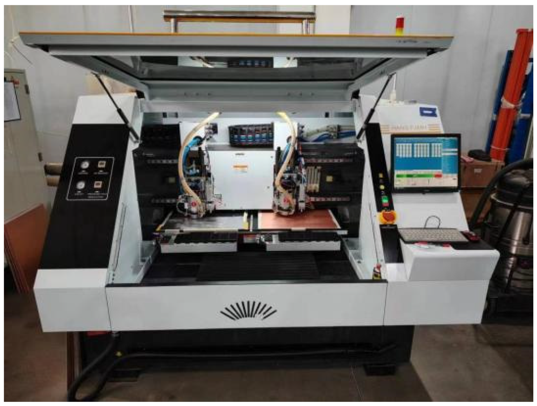
2.3. Drilling Experiments

In order to investigate the effect of different coating structures on the cutting performance of microdrills, AlTiN-coated cemented carbide microdrills with the deposition samples 1, 2, and 3 were used in the cutting tests. The tests were conducted using the PCB drilling machine (model: HANS-F2MH) from the commercial company Han’s CNC Science and Technology Co, Ltd. (Shenzhen, China), as shown in Figure 2. The PCB workpiece used was IT158-TG150 copper-clad laminate. The interlayer material between the upper and lower layers of copper foil was glass fiber-reinforced resin, and the thickness of each copper-clad laminate was 1.5 mm. Two copper-clad laminates were drilled through in a single pass during the drilling tests. The upper cover plate on workpiece was a coated aluminum sheet with a thickness of 0.18 mm, and the lower plate was a high-density fiber (HDF) board with a thickness of 2.5 mm. The spindle speed of the machine tool was 1.15 × 10⁵ r/min, the feeding speed was 1.5 m/min. The drilling test would be stopped when either the number of drilled holes reached 6000 or tool breakage occurred, whichever happened first. After that, an optical microscope (model: Keyence VHX2000, Osaka, Japan) and a scanning electron microscope were used to analyze the flank wear morphology of the tools and measure the flank wear area.

2.4. Testing Instruments

A Rockwell indentation instrument (model: Huayin HRS-150, Zhengzhou, China), an optical microscope (model: MoticECO-BINO-LED, Xiamen, China), a scanning electron microscope (model: Phenom Pure, The Netherlands), and an optical microscope (model: Keyence VHX2000) were used to examine the experimental results.

3. Experimental Results and Analysis

3.1. Analysis of Coating Adhesion Strength in Different Deposition Samples

Figure 3 shows the indentation morphology observed on the coating surface of the test block. The weak adhesion strength of the coating may have resulted in the coating flaking and the delamination of the coated tool during the cutting operation, and may have decreased the cutting performance of the tool as a result. The adhesion strength between the coating and the substrate was assessed by using a Rockwell indentation instrument, and a 588 N of load was applied to induce a damage of the coating layer near the edge of the indentation. After unloading, the indentation morphology of the coating was observed using optical microscopy (model: MoticECO-BINO-LED). The figures above show that the indentation edge of the coatings in sample 1 and sample 3 is a complete circular crater, implying a strong adhesion strength of the coatings. Conversely, some cracks and flaking occurred at the indentation edge of the coating in sample 2. This indicates that the adhesion strength of the coating in sample 2 was inferior to that of samples 1 and 3.

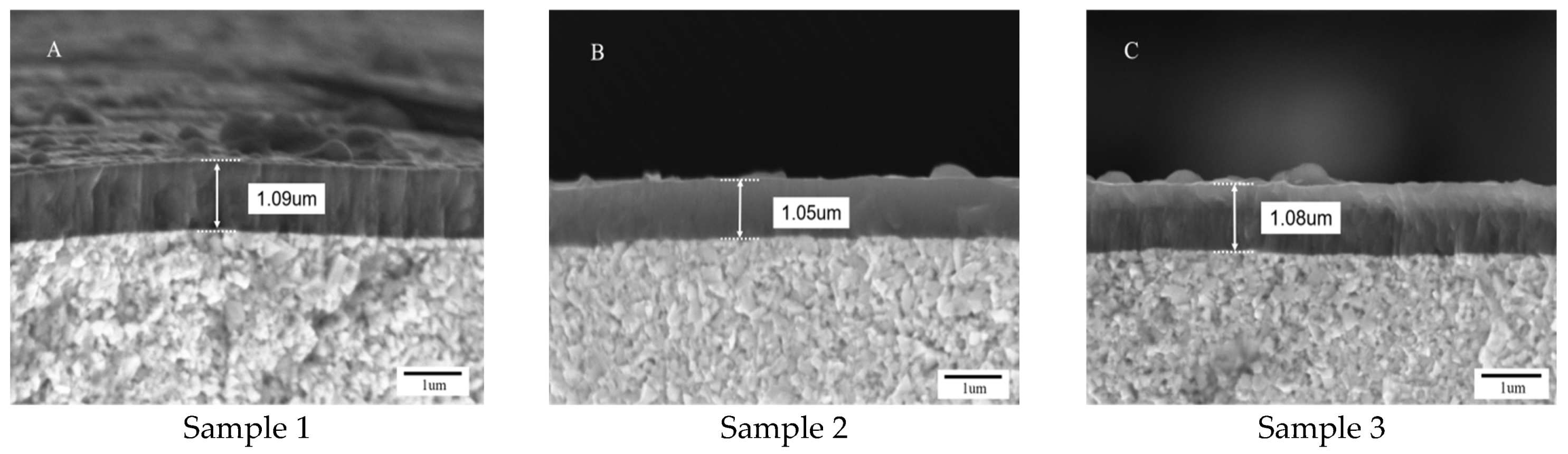
3.2. Analysis of Coating Morphology in Different Deposition Samples

Figure 4 shows the SEM images of the surface morphology of three different coatings deposited on microdrill. In all three samples, the coating surfaces are relatively smooth, without cracks or flaking. However, the presence of white particles and pit defects can be observed, and these are typical surface morphological features associated with coatings produced through the arc ion plating technology. The white particles were attributed to the splattering of metal droplets from the target material that adhered to and solidifying on the coating surface. The formation of pit defects occurred as a result of the detachment of particles with inadequate adhesion to the coating surface under the impact of high energy particles. The surface morphology of the microdrills on which three coating samples were deposited also indicates that the characteristics of the coating surface morphology were influenced by different substrate bias voltages. Compared with sample 1, the coatings in samples 2 and 3 exhibit fewer white particles and surface pits. This is attributed to the fact that, as the substrate bias increases during the deposition process, the energy of the bombarding charged target particles also increases. The higher bombardment energy enhances the re-sputtering effect, causing larger particles with lower adhesion that were deposited on the coating surface to be shattered or sputtered away under the sputtering effect. As a result, the coating grains were refined, leading to a relatively flat and smooth coating surface. Nevertheless, when the bias voltage is excessively elevated, the intense bombardment of charged particles may lead to the formation of micropores on the coating surface, consequently diminishing the adhesion strength of the coating [12,13]. The results of multiple experiments show that a coating surface with a relatively smooth and flat morphology can be achieved when the bias voltage is adjusted to 150 V.
Figure 5 shows the scanning electron microscopy images of the fracture cross sections of three different coatings. The cross-sectional structures of the coatings for the three samples all have a relatively dense structure without clear grain boundaries, micro-cracks, pinholes, or other defects. The interfacial adhesion between the coating and the substrate was strong for all three. The coating thicknesses of the three samples are approximately 1.09 μm, 1.05 μm, and 1.08 μm, respectively. It can be observed under a microscope that the AlTiN coating of sample 1 has a fine columnar crystal structure, and that the columnar crystal was interrupted and did not grow through the entire cross-section. In the deposition process of sample 2, the increasing of the bias voltage resulted in a higher ion energy. This produced a coating with a finer spherical nanocrystalline structure, enhanced coating density, and reduced coating thickness. The composite coating of sample 3 consists of alternating columnar crystals and nanocrystals, forming a dense multilayer composite structure. The interfaces between the layers are indistinct, suggesting strong interlayer bonding [14].

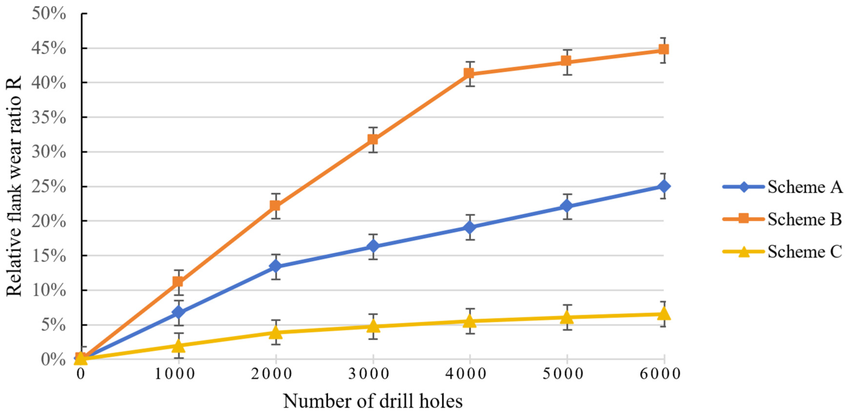
3.3. Comparative Analysis of the Tool Life in Different Deposition Samples

The flank wear is the main factor that affects the tool life of microdrills, as the area of the flank will decrease as a result of the wear failure. Because of the micro size of the cutting edges of microdrills, the degree of tool wear is usually assessed by measuring the area change of the flank. The morphology of the flank of the microdrills was examined using a scanning electron microscope before and after the drilling process. The relative wear area of the flank is defined as the ratio of the flank wear area to the original area. The formula for calculating this ratio is as follows:
R = ( S 0 S 1 ) / S 0 × 100 %
where R is the relative flank wear area ratio (%), S0 is the flank area of an original unused microdrill, and S1 is the remaining area of the flank after drilling.
Figure 6 illustrates the flank wear curves of the coated microdrills for three different deposition samples. The results indicate that, as the number of drilled holes increases, the flank wear of the microdrill with sample 2 shows the most rapid wear rate, whereas the flank wear of the microdrill with sample 3 shows the lowest wear rate. When the total number of the drilled holes reached 6000, the remanent flank area ratio of the microdrills was 75%, 55%, and 93% for sample 1, sample 2, and sample 3, respectively. It can be concluded that, under the same cutting conditions, the tool life of the microdrill with sample 3 is approximately 1.69 times longer than that of the microdrill with sample 2, and 1.25 times longer than that with Sample 1. It is evident that enhancing the adhesion strength between the coating and the substrate can reduce coating flaking and extend the service life of the microdrill.

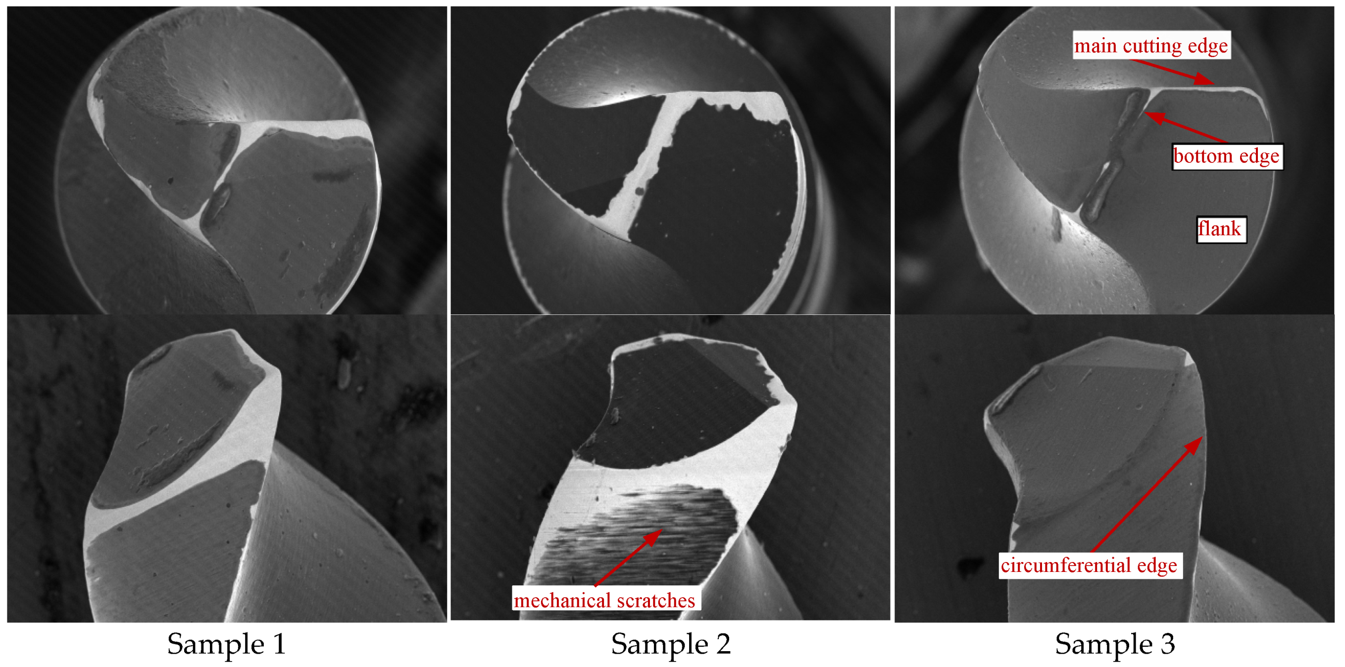
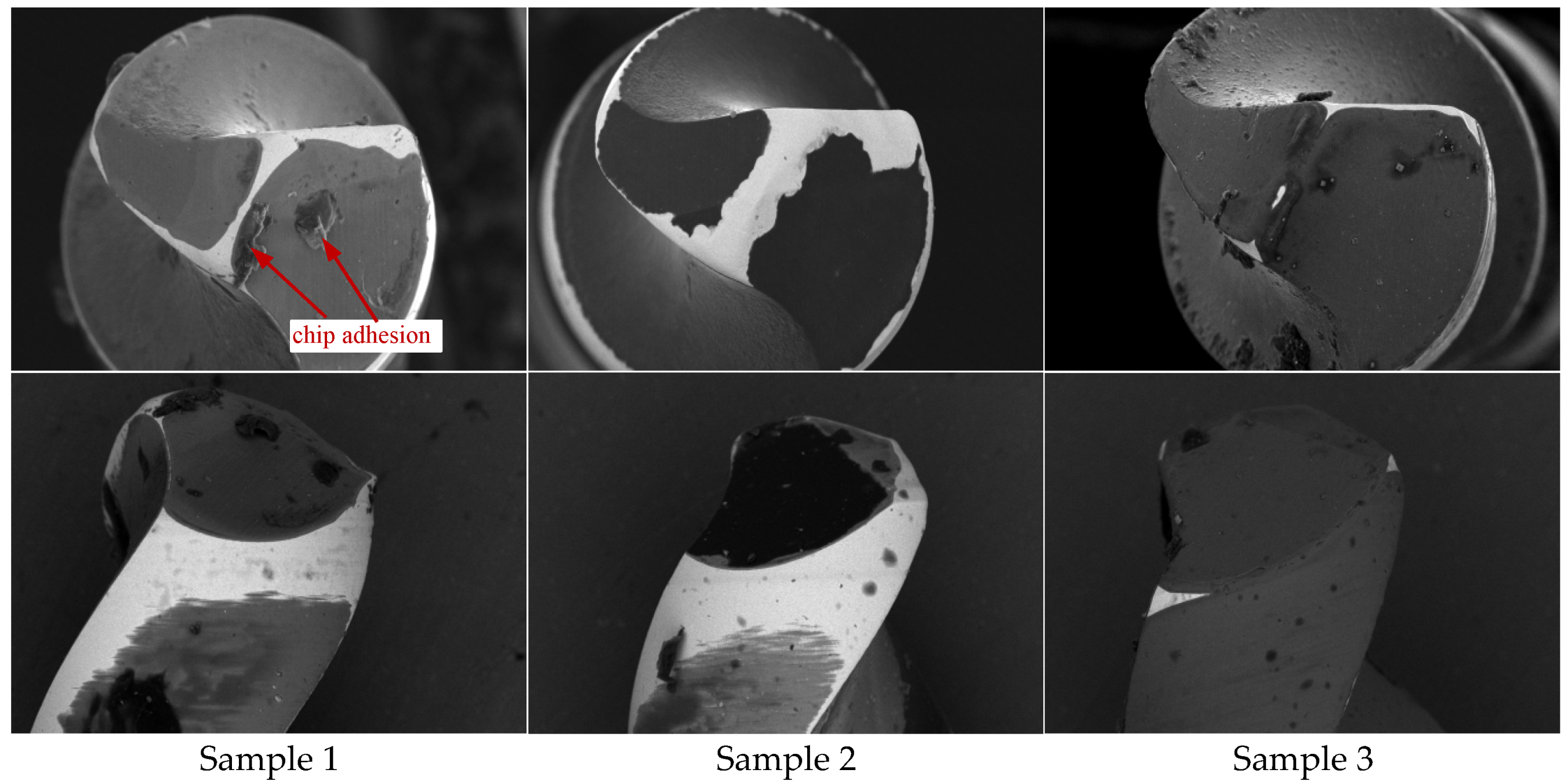
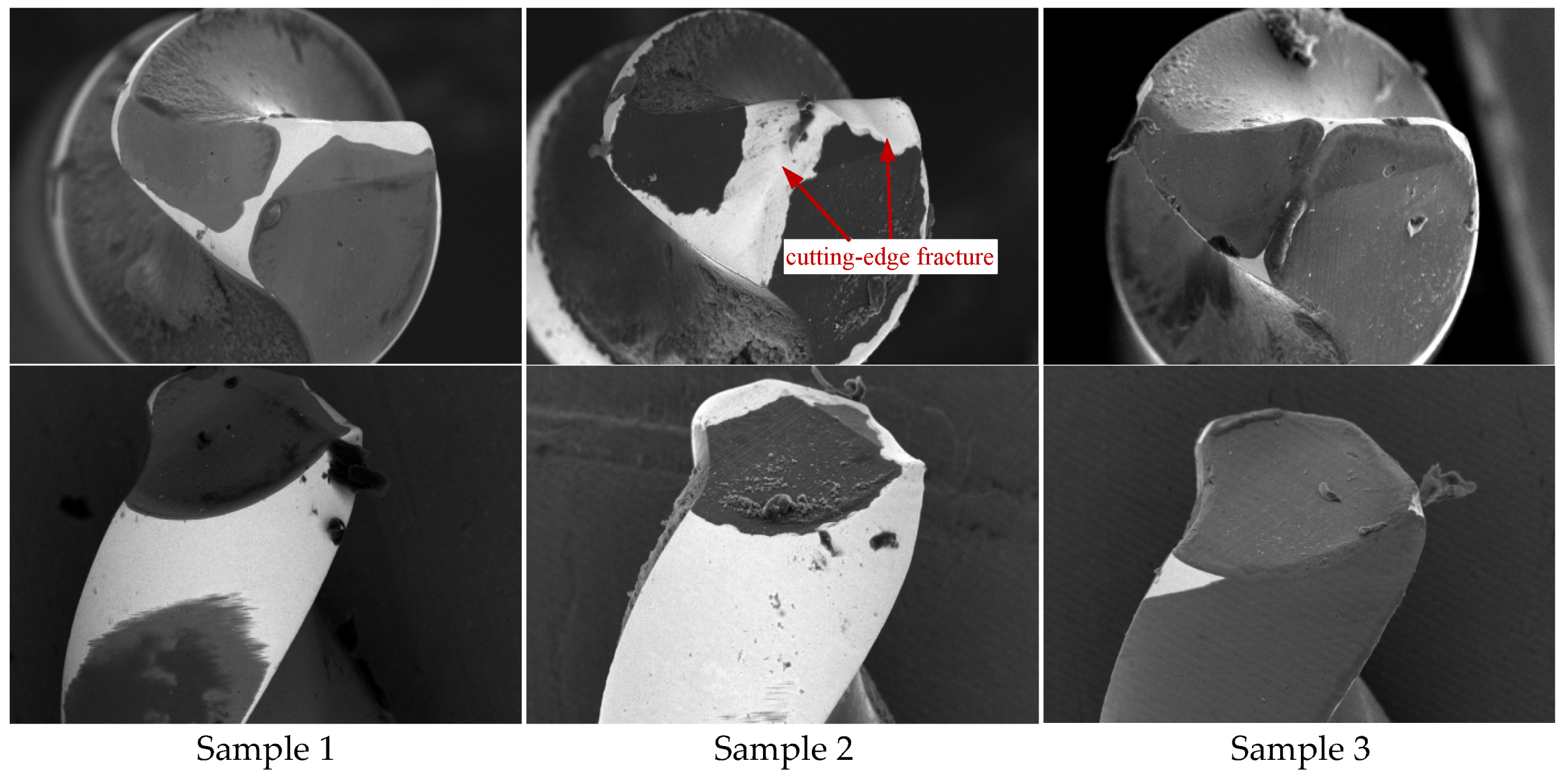
3.4. Analysis of the Wear Morphology of Microdrills in Different Deposition Samples

Figure 7, Figure 8 and Figure 9 show BSE images of wear on the flank and circumferential face of the AlTiN-coated microdrills with samples 1, 2, and 3 after drilling 2000, 4000, and 6000 holes, respectively. After the processing of 2000 holes, partial coating wear could be seen on the bottom edge, main cutting edge, and circumferential edge of the microdrill with sample 1. This resulted in the exposure of the underlying cemented carbide substrate. The bottom edge and main cutting edge of the microdrill with sample 2 were completely worn out, and flaking of the coating could be observed. There were also noticeable scratches on the circumferential face of the microdrill caused by the abrasive wear. The microdrill with sample 3 exhibited the smallest wear area on the main cutting edge, with the coating still covering the substrate after drilling. After processing 4000 holes, the wear area of the microdrill with sample 2 became pronounced, with obvious coating wear and flaking on the flank and circumferential face. The wear area of the microdrill with sample 1 increased at a consistent rate after processing 6000 holes, showing a smooth wear profile on the cutting edge. Conversely, the microdrill with sample 2 suffered severe wear failure, with the coating flaking, resulting in the fracture failure of the cemented carbide substrate at the bottom edge and the main cutting edge. However, the morphology of the microdrill tip with sample 3 remained almost unchanged, with the main and circumferential cutting edges wearing slowly, and no evident sign of wear failure on the tool face.
Figure 10 shows BSE images of the main cutting-edge wear on coated microdrills with different deposition samples after the processing of 4000 and 6000 holes. In comparison to the original unused microdrill, it is evident that the main cutting edge of the microdrill with sample 1 exhibits a normal wear state, and the main cutting edge of the microdrill with sample 2 demonstrates signs of breakage after the coating flaking. The main cutting edge of the microdrill with sample 3 shows the best wear resistance.
PCB is an anisotropic material that presents significant challenges in its machining process. The interaction between the microdrill and various materials, such as resin, glass fiber, and copper foil, could result in complex cutting actions and substantial friction. The periodic alternating loads applied on the microdrill generated by the high-speed entry and exit of the drill will significantly impact the microdrill and affect its cutting performance. In the drilling tests on PCBs, abrasive wear and coating flaking were seen to be the primary factors that influence the tool’s life. The wear morphology of the microdrills with three different coating structures reveals the presence of mechanical scratches within the wear region. This phenomenon is attributed to the brittle fracturing of glass fibers during the shearing process, in which the sharp edges of the fracture and the hard particles within the glass fiber chips caused abrasive wear through friction with the tool face. Chip adhesion can also be observed on the rake and flank of the microdrill. This is because the thermal softening of the resin caused it to mix with glass fiber and copper chips, causing adhesion to the microdrill. The adhesion of chips will interfere with the chip removal of the tool, impacting the quality of the drilled hole and potentially leading to breakage of the microdrill. Therefore, enhancing the hardness and adhesion strength of the coating, while simultaneously decreasing its surface roughness, will contribute positively to the tool life of the microdrill. The columnar crystal coating of sample 1 exhibits strong coating adhesion strength. However, its rough surface contributes to a high friction coefficient, which facilitates chip adhesion and consequently diminishes the drill’s wear resistance. The nanocrystalline coating of sample 2 exhibits a smooth surface, but the adhesion strength between the coating and substrate is inadequate. This results in flaking of the coating of the microdrill during machining processes, and can lead to cutting-edge fracture and fast wearing out of the drill. The columnar/nanocrystalline multilayer composite coating in sample 3 has a nanocrystalline structure on its surface to enhance its surface quality and a columnar crystal structure in the underlying layer to improve its adhesion strength to the substrate. The alternating structure of the multilayer coating can mitigate interlayer stress to a certain degree and inhibit crack propagation from the surface to the interior. As a result, the coating of sample 3 exhibits enhanced toughness and adhesion strength while maintaining a low surface friction coefficient, As a result, it can extend the tool’s life effectively [15,16].

4. Conclusions

  • Using arc ion plating technology, conventional AlTiN columnar crystal coatings and AlTiN nanocrystalline coatings were, respectively, deposited on cemented carbide specimens and PCB microdrill substrates. Meanwhile, a novel multilayer composite coating structure with alternating AlTiN columnar and nanocrystalline layers was also designed and deposited. Indentation tests and morphological analysis indicate that the coating adhesion strength of both the columnar crystal coating and the columnar/nanocrystalline composite coating surpassed that of nanocrystalline coatings, while the nanocrystalline coating exhibited the smoother surface.
  • The surface layer of the novel AlTiN columnar/nanocrystalline composite coating has a nanocrystalline structure that enhances its surface quality, while the underlying layer has a columnar crystal structure that improves its adhesion strength with the substrate. This multilayer composite structure effectively mitigates grain boundary sliding and inhibits crack propagation, thereby enhancing the toughness and adhesion strength of the coating and also reducing the friction between the microdrill and the chip.
  • PCB drilling experiments show that the tool life of the microdrill with the novel AlTiN columnar/nanocrystalline composite coating is approximately 1.69 times larger than that of the nanocrystalline-coated microdrills, and 1.25 times larger than that of the columnar crystal coated microdrills, under the same cutting conditions. The main factors that affect tool wear failures are abrasive wear and coating flaking.
Future research will focus on PVD-coated cemented carbide micro-tools with complex shapes, optimizing coating deposition process parameters to reduce the internal residual stress and enhance coating–substrate adhesion strength. Other ways to improve tool life will also be explored.

Author Contributions

X.Y.: writing—original draft, conceptualization, formal analysis, supervision. H.L.: formal analysis, methodology, investigation. Y.C.: experimental, visualization, project administration. Y.H.: data curation, resources, literature sorting. Z.S.: data curation, validation, funding acquisition. All authors have read and agreed to the published version of the manuscript.

Funding

We sincerely appreciate the Natural Science Foundation of Fujian Province (No. 2021J01853), and the Natural Science Foundation of Fujian Province (No. 2021J01850) for the fnancial support to this study.

Institutional Review Board Statement

The authors state that the present work is in compliance with the ethical standards.

Informed Consent Statement

All the authors consent to participate in this work.

Data Availability Statement

Data is contained within the article.

Conflicts of Interest

The authors declare no competing interests.

References

  1. Chen, C.; Lin, H.D.; Wu, J.Q. Research on high-speed drilling technology of PCB with super much holes. Print. Circuit Inf. 2022, 30, 19–23. [Google Scholar] [CrossRef]
  2. Lu, B.Y.; Ma, F.; Ma, D.Y. Microstructure and mechanical properties of thick Cr/CrN multilayer coatings by multi-arc ion plating. Rare Met. Mater. Eng. 2022, 51, 1558–1564. Available online: http://www.rmme.ac.cn/rmmeen/article/abstract/20210205?st=alljournals (accessed on 23 April 2025).
  3. Duan, J.N.; Li, W.Z.; Zhao, C.L.; Zhao, Y.; Dong, M.P.; Yuan, Z.W.; Li, J.L. Structure and Tribological Property of TiAlCN and TiAlN Coatings Prepared by Multi-arc Ion Plating. Surf. Technol. 2022, 51, 139–148. [Google Scholar] [CrossRef]
  4. Ran, L.J.; Zheng, S.T.; Fan, H.Y.; Xian, G.; Xiong, J.; Guo, Z.X.; Zhao, H.B.; Jing, Z.B. Properties of AlCrN coatings on cemented carbide prepared by arc ion plating assisted by gas ion source. Rare Met. Cem. Carbides 2021, 49, 94–98. [Google Scholar] [CrossRef]
  5. Azim, S.; Gangopadhyay, S.; Mahapatra, S.S.; Mittal, R.K.; Singh, R.K. Role of PVD coating on wear and surface integrity during environment-friendly micro-drilling of Ni-based superalloy. J. Clean. Prod. 2020, 272, 122741. [Google Scholar] [CrossRef]
  6. Alisir, S.H.; Evrensel, D. Investigation into Coating Structure and Wear Environment Effects on Tribological Properties of Piston Ring Coated with Monolayer TiAlN and Multilayer TiN/TiAlN. J. Mater. Eng. Perform. 2022, 31, 1654–1666. [Google Scholar] [CrossRef]
  7. Hu, J.; Sun, Y.S.; Chen, C.; Fu, L.Y.; Qu, J.G. Effect of TiAlN-based coating thickness on the stiffness and holes position accuracy of micro drills. Cem. Carbide 2021, 38, 424–433. [Google Scholar] [CrossRef]
  8. Skordaris, G.; Bouzakis, K.D.; Kotsanis, T.; Charalampous, P.; Bouzakis, E.; Breidenstein, B.; Bergmann, B.; Denkena, B. Effect of PVD film’s residual stresses on their mechanical properties, brittleness, adhesion and cutting performance of coated tools. CIRP J. Manuf. Sci. Technol. 2017, 18, 145–151. [Google Scholar] [CrossRef]
  9. Zhang, S.; Fan, Q.X.; Hao, X.H.; Wu, Z.H.; Ma, D.Z.; Cao, F.T.; Wang, T.G. Effect of deposition bias on the mechanics and high-temperature oxidation resistance of AlCrTiN nanocomposite coatings. Chin. Surf. Eng. 2023, 36, 104–113. [Google Scholar] [CrossRef]
  10. Liu, Y.; Ding, J.C.; Xu, Y.X.; Zhang, B.R.; Zhao, Z.Y.; Feng, L.M.; Zheng, J.; Wang, Q.M. Preparation and Cutting Performance of AlTiN Coatings by Arc Ion Plating and High Power Pulsed Magnetron Sputtering. Surf. Technol. 2022, 51, 57–65. [Google Scholar] [CrossRef]
  11. Xiao, B.J. Fabrication and Properties of AlCrN/AlTiSiN Nano-Layered Coatings on Cutting Tools. Ph.D. Thesis, Guangdong University of Technology, Guangzhou, China, 2019. (In Chinese). [Google Scholar] [CrossRef]
  12. Wang, Z.; Han, B.; Xiang, Y.; Tian, C.; Zou, C.; Fu, D. Effects of working pressure on microstructure and properties of TiBN/TiAlSiN nano-multilayer coatings. China Surf. Eng. 2020, 33, 77–85. Available online: https://qikan.cmes.org/zgbmgc/EN/10.11933/j.issn.1007-9289.20200911001 (accessed on 23 April 2025).
  13. Tillmann, W.; Grisales, D.; Stangier, D.; Thomann, C.A.; Debus, J.; Nienhaus, A.; Apel, D. Residual stresses and tribomechanical behaviour of TiAlN and TiAlCN monolayer and multilayer coatings by DCMS and HiPIMS. Surf. Coat. Technol. 2021, 406, 126664. [Google Scholar] [CrossRef]
  14. Ma, H.; Miao, Q.; Zhang, G.; Liang, W.; Wang, Y.; Sun, Z.; Lin, H. The influence of multilayer structure on mechanical behavior of TiN/TiAlSiN multilayer coating. Ceram. Int. 2021, 47, 12583–12591. [Google Scholar] [CrossRef]
  15. Lei, Z.; Zhu, X.; Li, Y.; Song, Z.; Liu, H.; Fu, Y.Q. Characterization and Tribological Behavior of TiAlN/TiAlCN Multilayer Coatings. J. Tribol.-Trans. Asme 2018, 140, 051301. [Google Scholar] [CrossRef]
  16. Yang, Y.; Xu, Y.X.; Chen, L.; Mayrhofer, P.H. Improved Ti-Al-N coatings through Ta alloying and multilayer architecture. Surf. Coat. Technol. 2017, 328, 428–435. [Google Scholar] [CrossRef]
Figure 1. The microdrill used in the cutting test.
Coatings 15 00520 g001
Figure 2. The PCB drilling machine used in the experiment.
Coatings 15 00520 g002
Figure 3. Indentation morphology of different coatings.
Coatings 15 00520 g003
Figure 4. Surface SEM images of microdrill cutting edge: Sample 1, Sample 2, and Sample 3 coatings.
Coatings 15 00520 g004
Figure 5. Cross-sectional SEM images of microdrill cutting edge: Sample 1, Sample 2, and Sample 3 coatings.
Coatings 15 00520 g005
Figure 6. Flank wear curves of the coated microdrill.
Coatings 15 00520 g006
Figure 7. BSE images of wear on the flank and circumferential face of microdrills after processing 2000 holes: Sample 1, Sample 2, and Sample 3 coatings.
Coatings 15 00520 g007
Figure 8. BSE images of wear on the flank and circumferential face of microdrills after processing 4000 holes: Sample 1, Sample 2, and Sample 3 coatings.
Coatings 15 00520 g008
Figure 9. BSE images of wear on the flank and circumferential face of microdrills after processing 6000 holes: Sample 1, Sample 2, and Sample 3 coatings.
Coatings 15 00520 g009
Figure 10. BSE images of the main cutting edge wear on coated microdrills with different deposition samples.
Coatings 15 00520 g010
Table 1. Base parameters of the tools.
Tool SpecificationTool Parameters
Drill Diameter × Flute Length × Overall Length (mm)Spiral Angle β (°)Apex Angle 2φ (°)Core Diameter DC (mm)First Relief Angle α1 (°)Secondary Relief Angle α2 (°)
0.3 × 6.2 × 38.145° (right)140°0.1561230
Table 2. Coating deposition process parameters.
SampleDeposition Time/MinWorking Pressure/PaBias Voltage/V (Negative Value)N2 Flow Rate/SccmTarget Current/A
AlTiAlTiAlTiAlTi
160440250150150150150
260150
35Alternate cycles 7 times40
2150
11 (surface layer)150
Disclaimer/Publisher’s Note: The statements, opinions and data contained in all publications are solely those of the individual author(s) and contributor(s) and not of MDPI and/or the editor(s). MDPI and/or the editor(s) disclaim responsibility for any injury to people or property resulting from any ideas, methods, instructions or products referred to in the content.

