Article

Improvement of Aluminium Film Adhesion on PMMA Using Pre-Layer and Specific Annealing

1
School of OptoElectronic Engineering, Changchun University of Science and Technology, Changchun 130000, China
2
Tianjin Mars Bird Technology Co. LDT., Tianjin 300000, China
*
Author to whom correspondence should be addressed.
Coatings 2018, 8(5), 186; https://doi.org/10.3390/coatings8050186
Submission received: 29 March 2018 / Revised: 5 May 2018 / Accepted: 11 May 2018 / Published: 15 May 2018
(This article belongs to the Special Issue Applications of Optical Thin Film Coatings)

Abstract

:
During the electron beam evaporation for deposition of an aluminium film, high-speed electrons decelerate when they bombard the material and part of the electron energy contributes to radiation. Due to the high sensitivity of polymethyl methacrylate (PMMA) to such radiation (in UV), the PMMA surface is degraded. This results in a weak surface of PMMA layer and decreases film adhesion. Based on the film interface adhesion mechanism and the relationship between film structure and stress, this research proposed and investigated a method for producing high quality Al reflective thin film on a PMMA surface with good adhesion. This was done by depositing a pre-layer of 20 nm Al using resistant evaporation to protect the PMMA surface from radiation damage, followed by the deposition of 80 nm Al using e-beam evaporation with ion assisted deposition. Using this method, an average reflectance of 88.6% was achieved in the wavelength range of 400–800 nm. The elastic modulus and hardness were tested by nanoindentation for the calculation of the thermal stress of the film. Adhesion was tested using the pressure strip peeling test and meets the military national standard.

1. Introduction

With the continuous development of resin synthesis technology, the performance of organic materials is continually improving. Among polymers, polymethyl methacrylate (PMMA) has high transmittance in the visible and near IR range, and the PMMA properties in impact resistance and tensile resistance are much better than that of normal glass. Al film on PMMA includes common applications such as use as a high reflection optical component in detection systems and use as a semiconductor mask or electrical connection component in integrated circuits [1,2,3], thus these Al films need to have good adhesion, good wear resistance, as well as other good mechanical properties. However, PMMA has high water absorption and its surface is easily damaged, this combined with the compressive stress of the metal film itself (caused by the different thermal expansion coefficients between metal film and PMMA), results in poor adhesion of the Al film on PMMA. The main aim of this research was to improve the adhesion of Al film on PMMA.
Dirk Hegemann used a surface plasma treatment method to improve the SiOx adhesion on an organic substrate and Petit used laser treatment on a PET surface, improving the adhesion of Al films on PET [4,5]. Liang Wang et al. achieved deposition of a 10 nm Au coating on PMMA with UV treatment of the PMMA surface [6]. Currently, the main approach to improving adhesion is through the treatment of the substrate surface and improvement of adhesion through investigation of the deposition technique. The process is less commonly found in the literature, furthermore, these reported films with good adhesion are very thin and unable to produce high reflective films. The resistive heating evaporation method is a common Al evaporation technique which produces porous films with poor adhesion due to low particle deposition energy. An improved method is required to achieve the desired high reflective Al film with good adhesion on a PMMA substrate.

2. Theory

2.1. Photon Induced Damage of PMMA

The advantageous properties of PMMA are high transmittance as well as being tough and light-weight. In detail, PMMA has a flexural strength of 140 MPa, a dielectric strength of 20.0 kV/m, and also at a wavelength of 587.6 nm, PMMA a refractive index of 1.491, optical transmittance of 92%, density of 1.19 g/cm3, and tensile modulus of 3200 MPa [7].
The chemical structure of PMMA is –[C5O2H8]– (the molecular weight of this repeating unit is 100.12 g/mol), including the ester structure –O–C=O, which plays an important role in photon transitions. Photon absorption properties are similar for polymers, and are shown in the Jablonski diagram below (Figure 1) [8].
Initially, the species is in a singlet ground state (S0) and the electrons are paired by spin. When excited, the species absorbs a photon and jumps to the S1 state. In this excited state, the species will return to the ground state (S0) via vibration, and a photon will be emitted as fluorescence. Electrons can only transit between the two states of the same spin. When the spin-orbital coupling is relatively large, different spin states will overlap and enter the triplet excited state (T1). The energy of the triplet excited state is lower than that of the singlet excited state, and here, when the excited species returns to the ground state, a phosphorescent photon is released. Thus, it can be seen that the absorbed photon can stimulate excitation either into the singlet state (S1) or the triplet state (T1) [9,10]. For this type of absorption, PMMA undergoes the typical Norrish I reactions [11]:
H 2 C = CCH 3 COOCH 3   h v   H 2 C = CCH 3 COO ·   +   · C
When the wavelength of photons λ < 200 nm (energy > 6.2 eV), bonds such as C–C (3.6 eV), C–H (3.7 eV) in the polymer may be broken, fracture of the main chain may occur, radicals due to loss of hydrogen atoms can be formed, and C=C bonds may also form [12]. The photon absorption of PMMA is shown in Figure 2.
As can be seen from the figure, the energy of the UV photon increases with decreasing wavelength. When the photon wavelength is less than 200 nm (photon energy is more than 7 eV), the absorbance of PMMA rapidly increases and approaches the maximum as the wavelength decreases. The chemical properties of PMMA cause it to degrade under the influence of UV photons, breaking the main chains and forming Low Molecular Weight Oxidized Materials (LMWOM) [13]. This causes defects and increases surface roughness, and therefore, it is important to consider photon radiation when depositing on PMMA.

2.2. Mechanism of Thin Film Adhesion

There are several factors that influence adhesion: physical attachment, chemical attachment, weak layer connection, and electrostatic force [14]. Adhesion between film and substrate, as well as the possible causes for film fracture/delamination are shown in Figure 3.
Figure 3 shows that surface defects and stress heavily impact on the film’s adhesion causing fracture and delamination. Currently, Al films are commonly deposited using the resistance heating evaporation method producing particles with low kinetic energy, these atoms have limited mobility, particularly once they are deposited onto the substrate surface [15]. Meanwhile, as the critical nucleation size is small, new nucleation sites will be continuously formed on the surface of the film producing columnar structures, these columnar structures have high void density. Thus, the film is very porous, has a large tensile stress, and is prone to film delamination. The more porous the film, the easier it is for moisture to seep in and hinder adhesion, causing reduction in the interacting forces between film and substrate, thereby weakening adhesion.
In order to reduce porosity and obtain a denser film, evaporated atoms require higher kinetic energy to gain higher mobility as the atoms reach the substrate surface. The e-beam evaporation method for deposition provides the particles with higher kinetic energy [16]. Adding ion beam assisted deposition technology, transferring momentum from the ions to the deposition atom, further increases the mobility of the deposition atoms, inhibiting columnar structure formation and thereby increasing film density, and strengthening adhesion between film and substrate.

2.3. Photon Radiation and Weak Boundary Layer Theory

When using the e-beam evaporation method for depositing Al films, there is an energy loss as the high-speed electrons bombard the substrate and rapidly decelerate. As the electrons approach the nucleus and interact with the Coulomb field, electrons rapidly decelerate and change direction, and the energy is converted to radiation [17]. The total energy loss of an electron is the sum of the loss of kinetic energy during collision and the energy loss due to radiation:
( d E d x ) tot =   ( d E d x ) rad +   ( d E d x ) coll
As all electrons have same mass and are very small, the energy loss from collisions between electrons is negligible, thus only the energy loss from interactions between the electrons and the nucleus is considered. This consideration includes the field from the high-speed electron and the screening effects from the electrons surrounding the nucleus. The collision cross-section relates not only to the electron energy but also to the atomic number (Z) of the colliding nucleus. For low energy fast electrons, the collision cross-section is:
d σ = 4 Z 2 r e 2 α d v v { ( 1 + ε 2 )   [ 1   ( ς ) 4   1 3   ln Z f ( z ) ]   2 3   ε [ 2 ( ς ) 4   1 3   ln Z f ( z ) ] }
Here, ε = E/E0, α = 1/137, f(z) = Coulomb correction term and ( ς ) =screen function.
For initial energy E 0   137 m e c 2 Z 1 3 and ξ ≥ 1, the cross section can be simplified to:
d σ = 4 Z r e 2 α d v v ( 1 +   ε 2   2 ε 3 ) [ ln 2 E 0 E m e c 2 ħ v   1 2 f ( z ) ]
The energy loss due to radiation can then be expressed as:
  ( d E d x ) rad =   N 0 V 0 ħ v   d σ d v ( E 0 ,   v ) d v
where N 0 =   ρ N a /   A ,   v 0 =   E 0 / h , for the number of atoms per cm2
Following the Bethe-Bloch equation, the photon radiation from a collision between electrons and a mass causes energy loss of:
  d E d x = N E 0 rad
The electron energy emitted by the 270° magnetic deflection electron gun is approximately 6 keV to 10 keV, neglecting the radiation due to electron diffusion and electron impact with the vacuum chamber wall, the energy of each radiated photon is estimated to be between 9 eV and 15 eV using the above equations. Combined with Figure 2, the photon radiations during e-beam evaporation cause fracture of the main polymer chains in PMMA, producing LMWOMs.
LMWOM shows high polarity on surfaces [18], but its adhesion to polymers is weak. According to Bikerman’s research [19], LMOWMs form a weak boundary layer which the Al film deposits onto, but as the weak boundary layer of LMOWMs is weakly bonded to the bulk PMMA, the adhesion between the substrate and the film (Al plus thin UV induced LMWOM surface layer) is very poor.
In order to obtain dense films with good adhesion to the substrate, the reduction of the adverse effects from photon radiation to the PMMA substrate is important, thus a method to protect the substrate surface needs to be investigated. Since resistance heating evaporation uses the Joule heat generated by the heater to obtain sufficient kinetic energy for the molecules or atoms of the evaporation material, the generation of UV photon radiation can be avoided. Considering the influence of stress on adhesion, the thickness of the film deposited using resistance heating evaporation should be matched with the stress of the film deposited by e-beam evaporation. By considering the exponential decay of photon radiation in the aluminium film, and after several experiments, 20 nm Al film was chosen to be deposited by resistance heating evaporation as the protective layer for PMMA surface, blocking the UV photon generated from e-beam deceleration.

2.4. Hardness, Indentation Test

Nanoindentation was used to measure the elastic modulus and hardness of the film. Acquisition of complete loading/unloading data allows analysis by obtaining the contact area between the tip and the measured material, which then allows calculation of the elastic modulus and hardness of the sample [20]. The Berkovich indentation tip has a triangular pyramid shape. Figure 4 illustrates the nano-indentation process on a thin film.
The equivalent elastic modulus can be obtained from the unloading curve
E r =   π 2 β   ·   S A
Here, S is the experimentally measured stiffness of the upper portion of the unloading data, A is the projected area of the elastic contact, β is correction factor for the tip shape symmetry (typically β = 1). Hardness refers to the resistive ability of a material against an external force applied to its surface, and can characterize the stiffness of the material and its ability to resist local deformation. The hardness formula is
H =   P A

3. Experimental Procedures

Experiment apparatus: Opco-900 vacuum coating machine. This machine has a pair of resistance evaporation sources and a double e-type electron gun. For higher efficiency and denser film deposition, a spiral tungsten wire was chosen as the source for resistant heating deposition while the source of Al had purity of more than 99.99%. PMMA substrate was provided by Mitsubishi Corporation (serial VH001), 15 mm × 15 mm square with 2 mm thickness. After removing protective films on both sides, the PMMA was cleaned three times with ultrasound and then baked in an oven (as PMMA is an absorbent for water, a high temperature bake was conducted). PMMA has a Vicat soft point at 105 °C, above this temperature shape deformation occurs. Experimentally, it was found that the appropriate bake temperature was around 80% to 85% of the Vicat soft point: no shape deformation of PMMA and effective removal of moisture [21]. Thus, a bake at 80 °C for 1 h was carried out after cleaning.
The baked substrate was placed into the vacuum chamber and pumping down begun; once the vacuum reached 1.0 × 10⁻³ Pa, deposition was started. The process parameters are tabled below (Table 1): the first Al layer is the protective layer, deposited using resistant heating evaporation, (note: this deposition is done without using Ion Assisted Deposition, IAD); the second layer of Al film is deposited using electron beam evaporation with IAD. A graphite crucible was used during Al film deposition.
Ion source parameters are shown in Table 2.
After deposition, different annealing of samples was done to compare the effect of annealing on adhesion properties. One batch of samples was annealed linearly, while another batch of samples was annealed in steps.
For verification of the UV radiation damaging PMMA theory, another sample was prepared for water contact angle test, where the PMMA was exposed to UV radiation without Al film deposition but keeping the relevant conditions the same. In order to achieve this, a high purity copper crucible was used for its good thermal conduction, this allowed the thermal energy to be rapidly lost and prevented the Al material from being heated sufficiently for evaporation. Therefore, no deposition of Al occurred. The dose of UV radiation exposed to the PMMA surface should be the same as for the above Al deposited samples. A KSV 200 (KSV, Stockholm, Sweden) apparatus was used to measure the water contact angle.
For the samples prepared with Al films, measurements were done after deposition. These analyses include a spectral test, a hardness test, and a tape pull test (for adhesion). For the spectral test, a Shimadzu UV-3150 (Shimadzu, Kyoto, Japan) spectrophotometer was used. Hardness and the Young’s modulus were measured using a nanoindentation machine: KEYSIGHT G200 (Agilent, Santa Clara, CA, USA). The obtained Young’s moduli were then used to estimate stress of the Al film, based on this assumption: the thermal stress is the main contributor. A stress analysis system, KSVMOS, was used to verify the estimated stress values. An adhesion test, tape pull test was done using 3 M scotch 610 test tape: stickiness of (10 ± 1) N/25 mm, and keeping the tape pull angle at 90° to the film surface. This was repeated three times with a comparison conducted between samples of Al coating with 20 nm protective layer and Al coating without protective layer. Both, the remaining polymer and the aluminium interfaces were then analysed. The adhesion of the aluminium film was investigated by performing a tape test according to the military national standard.

4. Results and Discussion

4.1. Water Contact Angle Test of PMMA Surface

As discussed in the previous sections, the UV radiation caused by electron deceleration easily breaks the surface C–C chain, producing LMWOMs. These LMWOMs are usually more hydrophilic than the original long PMMA chains. Measurements of the water contact angles on the PMMA surface, with and without UV treatment, are shown in Figure 5.
The water contact angle is 78° before UV radiation, and 65° after UV radiation. As discussed in Section 2, the PMMA surface absorbs the UV radiation and results in the surface degradation which causes the change in the water surface contact angle.

4.2. Spectral Analysis

A spectral test of Al coated samples is shown in Figure 6, the average reflectance was 88.6% and meets the spectral requirements for metal mirrors.

4.3. Elastic Modulus and Hardness Test

Hardness tests with anindentation depth of 100 nm were carried out (measurements were repeated to obtain an average), the loading/unloading curves are shown in Figure 7.
The elastic modulus and hardness of the aluminium film were obtained from the loading/unloading curve with the results shown in Table 3.
The main causes of stress in thin films are thermal stress and internal stress. Al is a soft metal, and for soft metals, internal stresses are small, particularly as Al is a thin film in this case; thus Al internal stress contributes little to the stress of the film. On the other hand, there is a large difference between the thermal expansion coefficients of Al and PMMA, therefore, the main contributor to the film stress is thermal stress. The expression for thermal stress is given below:
σ th = ( σ s   σ f ) E f Δ T 1     V f
where σ s, σ f are the thermal expansion coefficients of the base material and the film material, Ef is the elastic modulus of the film, and ΔT is the difference between the film deposition temperature and the temperature during sample analysis. The thermal expansion coefficient of PMMA substrate is 6 × 10⁻⁵; the thermal expansion coefficient of the Al film is 2.32 × 10⁻⁵; the Poisson’s ratio is 0.3 and the elastic modulus is 5.494. Using the above formula, the thermal stress of the film was found to be σth = −0.315ΔT (MPa), which relates only to ΔT.
To verify the calculation, analysis of the thin film stress was also done using KSVMOS; Figure 8 shows the results:
From Figure 8, the stress can be read to be the average of compressive stress −10 MPa. Due to the film being only 100 nm, there was difficulty in obtaining an accurate measurement, however the trend of stress is correct: compressive and in the range of −10 MPa.
It is evident that, different to the deposition on the glass substrate, the magnitude of compressive stress in the Al film deposited on the PMMA substrate is dependent on the temperature difference between the deposition temperature and the measurement temperature, therefore it would be ideal for the deposition temperature to be at room temperature. However, PMMA is highly absorbent to water, and room temperature deposition will not effectively have had the moisture removed from the substrate, which could cause serious delamination issues.
An appropriate annealing method can be used to effectively remove moisture. There is also an additional advantage from annealing. During low temperature annealing, atoms exchange energy mainly via lattice vibrations and some dislocations may heal, reducing the internal stress of the thin film. However, prolonged annealing may lead to fatigue aging of the film, and residual impurities in the vacuum chamber may react with the film [22,23], thus affecting the mechanical and optical properties of the film. Figure 9 illustrates the film performance (tape pull test for adhesion), with varying annealing conditions.

4.4. Adhesion Test

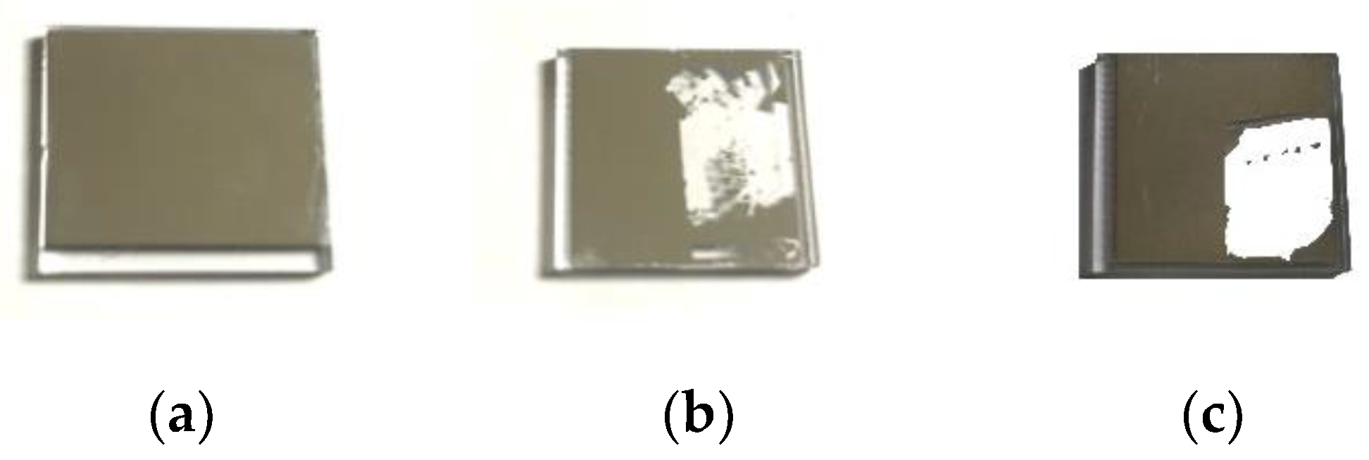
The adhesion test used is the tape full test, where tape is attached to the sample and then peeled off. The adhesion is then judged on the extent of the film delamination. The measurement process is simple and has good repeatability. This was repeated three times with comparison done between Al coating with 20 nm protective layer and Al coating without protective layer, shown in Figure 10:
As illustrated in Figure 10, adhesion of Al film (deposited using e-beam evaporation with IAD) that has the 20 nm Al protective layer deposited by the resistant heating evaporation method on PMMA substrate is superior to the Al film without the protective layer. The adhesion results in Figure 10b,c show no significant difference, meaning that the IAD is not the key cause of bad adhesion. The adhesion of Al film with a pre-deposited protective 20 nm Al layer (thermal evaporation) meets the military national standard.

5. Conclusions

A method to protect a PMMA substrate surface for improved adhesion of Al film was developed in this research by studying the mechanism of photon radiation generation due to electron deceleration, calculating the photon radiation generated during electron beam deposition, considering the influence of the radiation on the PMMA substrate, and combining with weak boundary layer theory. The effect of the film formation and its structure on stress and adhesion was also investigated. The elastic modulus and hardness of the film were measured quantitatively by nanoindentation. Spectral and adhesion tests also showed that the Al reflective films meet the optical requirements for reflective films and the military national standard for adhesion. With the increasing applications of polymer materials, how to prepare a variety of functional films on polymers with good adhesion is a future step in research.

Author Contributions

X.F.: Put forward the research basis theory and design experiment. G.Z.: Experimental operation, data collection, data analysis, test data interpretation, manuscript writing. J.Z.: Experimental data sort out, verify the experimental data and theoretical consistency .K.G.: Chart production, manuscript modification, experimental data analysis. Y.P.: Test data analysis, document retrieval.

Funding

This research received no external funding.

Conflicts of Interest

The authors declare no conflict of interest.

References

  1. Baldini, F.; Carloni, A. Optical PMMA chip suitable for multianalyte detection. IEEE Sens. J. 2008, 8, 1305–1309. [Google Scholar] [CrossRef]
  2. Tambe, N.S.; Bhushan, B. Micro/nanotribological characterization of PDMS and PMMA used for BioMEMS/NEMS applications. Ultramicroscopy 2005, 105, 238–247. [Google Scholar] [CrossRef]
  3. Zhang, H.; Zhang, R.; Liu, X.; Liang, Y.; Zhang, X.; Zhu, M. Fabrication of PMMA superhydrophobic surface coating by hot embossing/spray method. J. Tianjin Univ. 2015, 12, 1071–1076. (In Chinese) [Google Scholar] [CrossRef]
  4. Hegemann, D.; Brunner, H.; Oehr, C. Plasma treatment of polymers for surface and adhesion improvement. Nucl. Inst. Methods Phys. Res. B 2003, 208, 281–286. [Google Scholar] [CrossRef]
  5. Laurens, P.; Petit, S.; Arefi-Khonsari, F. Study of PET surfaces after laser or plasma treatment: surface modifications and adhesion properties towards Al deposition. Plasmas Polym. 2003, 8, 281–295. [Google Scholar] [CrossRef]
  6. Wang, L. Study on the Adhesion Strength of Metal Films on PMMA Substrate by UV Surface Treatment; Dalian University of Technology: Dalian, China, 2015. [Google Scholar]
  7. Mitsubishi Rayon Acrypet®. Available online: http://www.matweb.com/search/QuickText.aspx?SearchText=7.%09MitsubishiRayon%20Acrypet (accessed on 14 May 2018).
  8. Jaboski, A. Efficiency of anti-stokes fluorescence in dyes. Nature 1933, 131, 839–840. [Google Scholar] [CrossRef]
  9. Scaiano, J.C.; Stamplecoskie, K.G.; Hallett-Tapley, G.L. Photochemical norrish type I reaction as a tool for metal nanoparticle synthesis: importance of proton coupled electron transfer. Chem. Commun. 2012, 48, 4798–4808. [Google Scholar] [CrossRef] [PubMed]
  10. Cui, G.; Sun, Z.; Fang, W. Adiabatic and nonadiabatic bond cleavages in Norrish type I reaction. J. Phys. Chem. A 2011, 115, 10146–10153. [Google Scholar] [CrossRef] [PubMed]
  11. Dekhtyar, Y.; Griva, A.; Lancere, L.; Andersons, B.; Sansonetti, E. Wettability of the PMMA surface caused by its polarization due to UV radiation. In Proceedings of the Applications of Ferroelectrics Held Jointly with 2012 European Conference on the Applications of Polar Dielectrics and 2012 International Symp Piezoresponse Force Microscopy and Nanoscale Phenomena in Polar Materials (ISAF/ECAPD/PFM), Aveiro, Portugal, 9–13 July 2012; pp. 1–3. [Google Scholar] [CrossRef]
  12. Strobel, M.; Corn, S.; Lyons, C.S.; Korba, G.A. Plasma fluorination of polyolefins. J. Polym. Sci. Part A Polym. Chem. 1987, 25, 539–545. [Google Scholar] [CrossRef]
  13. Bikerman, J.J. Cause of poor adhesion boundary. Ind. Eng. Chem. 1967, 59, 40–44. [Google Scholar] [CrossRef]
  14. Volinsky, A.A.; Tymiak, N.I.; Kriese, M.D.; Hutchinson, J.W. Quantitative modelling and measurement of copper thin film adhesion. Mater. Res. Soc. Symp. Proc. 1998, 539, 277–290. [Google Scholar] [CrossRef]
  15. Furuuchi, S.; Sakata, H.; Aikawa, K. Microhardness of silica films prepared by resistance heating and electron beam evaporation. Jpn. J. Appl. Phys. 1974, 13, 1905–1906. [Google Scholar] [CrossRef]
  16. Al-Kuhaili, M. Electron Beam Evaporation. Encyclopedia Nanotechnol. 2012, 37, 718. [Google Scholar] [CrossRef]
  17. Arsenyev, S.A.; Koryagin, S.A. Electromagnetic radiation from positive-energy bound electrons in the Coulomb field of a nucleus at rest in a strong uniform magnetic field. J. Exp. Theor. Phys. 2012, 114, 913–922. [Google Scholar] [CrossRef]
  18. Kamińska, A.; Kaczmarek, H.; Kowalonek, J. The influence of side groups and polarity of polymers on the kind and effectiveness of their surface modification by air plasma action. Eur. Polym. J. 2002, 38, 1915–1919. [Google Scholar] [CrossRef]
  19. Bikerman, J.J. The fundamentals of tackiness and adhesion. J. Colloid Sci. 1947, 2, 163–175. [Google Scholar] [CrossRef]
  20. Li, H.; Vlassak, J.J. Determining the elastic modulus and hardness of an ultra-thin film on a substrate using nanoindentation. J. Mater. Res. 2009, 24, 1114–1126. [Google Scholar] [CrossRef]
  21. Aouachria, K.; Belhaneche-Bensemra, N. Miscibility of PVC/PMMA blends by vicat softening temperature, viscometry, DSC and FTIR analysis. Polym. Test. 2006, 25, 1101–1108. [Google Scholar] [CrossRef]
  22. Misra, A.; Nastasi, M. Evolution of tensile residual stress in thin metal films during energetic particle deposition. J. Mater. Res. 1999, 14, 4466–4469. [Google Scholar] [CrossRef]
  23. Baker, S.P.; Saha, K.; Shu, J.B. Effect of thickness and Ti interlayers on stresses and texture transformations in thin Ag films during thermal cycling. Appl. Phys. Lett. 2013, 103, 191905. [Google Scholar] [CrossRef]
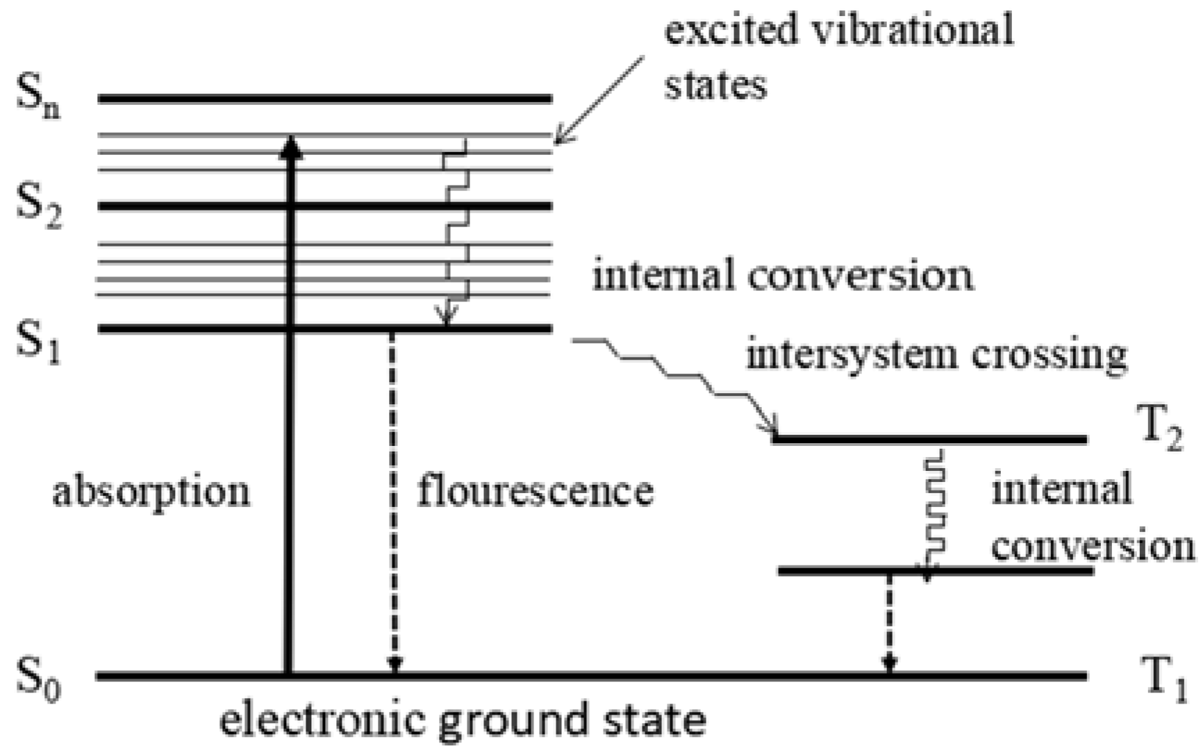
Figure 1. Simplified Jablonski diagram (S = singlet state, T = triplet state).
Coatings 08 00186 g001
Figure 2. Absorption spectrum of polymethyl methacrylate (PMMA) in the UV range.
Coatings 08 00186 g002
Figure 3. Illustration of film adhesion and fracture mechanism.
Coatings 08 00186 g003
Figure 4. Nano-indentation test on a thin film using Berkovich tip.
Coatings 08 00186 g004
Figure 5. (a) Shows the water contact angle on untreated PMMA; (b) shows the water contact angle of PMMA after UV radiation.
Coatings 08 00186 g005
Figure 6. Spectrum of Al reflective coating on PMMA.
Coatings 08 00186 g006
Figure 7. The loading/unloading curves of measurement. L1, L2, L3 refer to the first, second, third measurements respectively.
Coatings 08 00186 g007
Figure 8. The stress of Al coating on PMMA.
Coatings 08 00186 g008
Figure 9. Film performance for different annealing temperature curves: S1 film survived one tape pull test (sample annealed and cooled linearly); S2 survived three pull tests (sample annealed and cooled in steps).
Coatings 08 00186 g009
Figure 10. Sample condition after tape pull test (a) with 20 nm Al protective layer produced by thermal deposition, and then 100 nm Al deposition using e-beam with Ion Assisted Deposition, (IAD) (b) deposited by electron beam vapour deposition with IAD (without pre-layer); (c) the first pre-layer of 20 nm deposited using only electron beam vapour deposition then deposition completed using e-beam with IAD.
Coatings 08 00186 g010
Table 1. Process Parameters. (IAD = Ion Assisted Deposition).
The Order of LayerThickness (nm)The Way of EvaporationVacuum Degree (Pa)Substrate Temperature (°C)Deposition Rate (nm/s)IAD Situation
The first layer20Resistant Heating1.0 × 10−3801Without
The second layer80Electron-beam1.0 × 10−3801.5With
Table 2. Parameters of the Kaufmann ion source.
ParametersValue
Argon flow/sccm15
Plate voltage/V415
Acceleration/V275
Anode voltage/V50
Neutralizing current/A13.5
Cathodic current/A16
Ion beam current/mA50
Table 3. The result of nano-indentation.
TestModulus (GPa)Drift Coefficient (nm/S)Load (mN)Hardness (MPa)
15.9620.0760.0470.362
25.9980.0460.0550.302
35.3480.0530.050.308
Mean5.760.1750.050.324