Selection of Optimum Binder for Silicon Powder Anode in Lithium-Ion Batteries Based on the Impact of Its Molecular Structure on Charge–Discharge Behavior


Abstract
:1. Introduction
2. Experiments
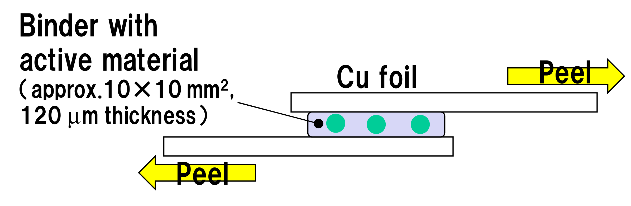
2.1. Shear Peeling
2.2. Compressive Strength
2.3. Evaluation of Electrochemical Properties of Resins as Active Materials
3. Results and Discussion
4. Conclusions
Author Contributions
Funding
Acknowledgments
Conflicts of Interest
References
- Zubi, G.; Spertino, F.; Carvalho, M.; Adhikari, R.S.; Khatib, T. Development and assessment of a solar home system to cover cooking and lighting needs in developing regions as a better alternative for existing practices. Sol. Energy 2017, 155, 7–17. [Google Scholar] [CrossRef]
- Akikur, R.K.; Saidur, R.; Ping, H.W.; Ullah, K.R. Comparative study of stand-alone and hybrid solar energy systems suitable for off-grid rural electrification: A review. Renew. Sust. Energy Rev. 2013, 27, 738–752. [Google Scholar] [CrossRef]
- Bekele, G.; Palm, B. Feasibility study for a standalone solar-wind-based hybrid energy system for application in Ethiopia. Appl. Energy 2010, 87, 487–495. [Google Scholar] [CrossRef]
- Carroquino, J.; Dufo-Lopez, R.; Bernal-Agustin, J.L. Sizing of off-grid renewable energy systems for drip irrigation in Mediterranean crops. Renew. Energy 2015, 76, 566–574. [Google Scholar]
- Diouf, B.; Pode, R. Potential of lithium-ion batteries in renewable energy. Renew. Energ. 2015, 76, 375–380. [Google Scholar] [CrossRef]
- Graham, V.A.; Hollands, K.G.T. A method to generate synthetic hourly solar-radiation globally. Sol. Energy 1990, 44, 333–341. [Google Scholar] [CrossRef]
- Barre, A.; Deguilhem, B.; Grolleau, S.; Gerard, M.; Suard, F.; Riu, D. A review on lithium-ion battery ageing mechanisms and estimations for automotive applications. J. Power Sources 2013, 241, 680–689. [Google Scholar] [CrossRef] [Green Version]
- Wagner, F.T.; Lakshmanan, B.; Mathias, M.F. Electrochemistry and the future of the automobile. J. Phys. Chem. Lett. 2010, 1, 2204–2219. [Google Scholar] [CrossRef]
- Li, L.; Wu, Z.; Yuan, S.; Zhang, X.B. Advances and challenges for flexible energy storage and conversion devices and systems. Energ. Env. Sci. 2014, 7, 2101–2122. [Google Scholar] [CrossRef]
- Goodenough, J.B. Evolution of strategies for modern rechargeable batteries. Acc. Chem. Res. 2013, 46, 1053–1061. [Google Scholar] [CrossRef]
- Yuan, S.F.; Wu, H.J.; Yin, C.L. State of charge estimation using the extended kalman filter for battery management systems based on the arx battery model. Energies 2013, 6, 444–470. [Google Scholar] [CrossRef]
- Zhang, C.; Li, K.; Pei, L.; Zhu, C.B. An integrated approach for real-time model-based state-of-charge estimation of lithium-ion batteries. J. Power Sources 2015, 283, 24–36. [Google Scholar] [CrossRef] [Green Version]
- Mayyas, A.; Omar, M.; Hayajneh, M.; Mayyas, A.R. Vehicle’s lightweight design vs. electrification from life cycle assessment perspective. J. Clean. Prod. 2017, 167, 687–701. [Google Scholar] [CrossRef]
- Snoussi, J.; Ben Elghali, S.; Benbouzid, M.; Mimouni, M.F. Auto-adaptive filtering-based energy management strategy for fuel cell hybrid electric vehicles. Energies 2018, 11, 8. [Google Scholar] [CrossRef]
- Dufo-Lopez, R.; Bernal-Agustin, J.L.; Yusta-Loyo, J.M.; Dominguez-Navarro, J.A.; Ramirez-Rosado, I.J.; Lujano, J.; Aso, I. Multi-objective optimization minimizing cost and life cycle emissions of stand-alone PV-wind-diesel systems with batteries storage. Appl. Energy 2011, 88, 4033–4041. [Google Scholar] [CrossRef]
- Mulder, G.; De Ridder, F.; Six, D. Electricity storage for grid-connected household dwellings with PV panels. Sol. Energy 2011, 84, 1284–1293. [Google Scholar] [CrossRef]
- Tong, S.; Fung, T.; Klein, M.P.; Weisbach, D.A.; Park, J.W. Demonstration of reusing electric vehicle battery for solar energy storage and demand side management. J. Energy Storage 2017, 11, 200–210. [Google Scholar] [CrossRef]
- Delucchi, M.A.; Lipman, T.E. An analysis of the retail and lifecycle cost of battery-powered electric vehicles. Transp. Res. Part D-Transp. Environ. 2001, 6, 371–404. [Google Scholar] [CrossRef] [Green Version]
- Goodenough, J.B. Challenges for rechargeable li batteries. Chem. Mater. 2010, 22, 587–603. [Google Scholar] [CrossRef]
- Kasavajjula, U.; Wang, C.S.; Appleby, A.J. Nano- and bulk-silicon-based insertion anodes for lithium-ion secondary cells. J. Power Sources 2007, 163, 1003–1039. [Google Scholar] [CrossRef]
- Wu, H.; Chan, G.; Choi, J.W.; Ryu, I.; Yao, Y.; McDowell, M.T.; Lee, S.W.; Jackson, A.; Yang, Y.; Hu, L.B.; et al. Stable cycling of double-walled silicon nanotube battery anodes through solid-electrolyte interphase control. Nat. Nanotech. 2012, 7, 309–314. [Google Scholar] [CrossRef] [PubMed]
- Verma, P.; Maire, P.; Novak, P. A review of the features and analyses of the solid electrolyte interphase in Li-ion batteries. Electochim. Acta 2010, 55, 6332–6341. [Google Scholar] [CrossRef]
- Komaba, S.; Murata, W.; Ishikawa, T.; Yabuuchi, N.; Ozeki, T.; Nakayama, T.; Ogata, A.; Gotoh, K.; Fujiwara, K. Electrochemical na insertion and solid electrolyte interphase for hard-carbon electrodes and application to na-ion batteries. Adv. Func. Mater. 2011, 21, 3859–3867. [Google Scholar] [CrossRef]
- Bates, J.B.; Dudney, N.J.; Neudecker, B.; Ueda, A.; Evans, C.D. Thin-film lithium and lithium-ion batteries. Solid State Ion. 2011, 135, 33–45. [Google Scholar] [CrossRef]
- Quartarone, E.; Mustarelli, P. Electrolytes for solid-state lithium rechargeable batteries: Recent advances and perspectives. Chem. Soc. Rev. 2011, 40, 2525–2540. [Google Scholar] [CrossRef]
- Knauth, P. Inorganic solid Li ion conductors: An overview. Solid State Ion. 2009, 180, 911–916. [Google Scholar] [CrossRef]
- Croce, F.; Appetecchi, G.B.; Persi, L.; Scrosati, B. Nanocomposite polymer electrolytes for lithium batteries. Nature 1998, 394, 456–458. [Google Scholar] [CrossRef]
- Song, J.Y.; Wang, Y.Y.; Wan, C.C. Review of gel-type polymer electrolytes for lithium-ion batteries. J. Power Sources 1999, 77, 183–197. [Google Scholar] [CrossRef]
- Meyer, W.H. Polymer electrolytes for lithium-ion batteries. Adv. Mater. 1998, 10, 439. [Google Scholar] [CrossRef]
- Stephan, A.M. Review on gel polymer electrolytes for lithium batteries. Euro. Poly. Jour. 2006, 42, 21–42. [Google Scholar] [CrossRef]
- Gadjourova, Z.; Andreev, Y.G.; Tunstall, D.P.; Bruce, P.G. Review of gel-type polymer electrolytes for lithium-ion batteries. Nature 2001, 412, 520–523. [Google Scholar] [CrossRef] [PubMed]
- Horike, S.; Umeyama, D.; Kitagawa, S. ion conductivity and transport by porous coordination polymers and metal-organic frameworks. Acc. Chem. Res. 2013, 46, 2376–2384. [Google Scholar] [CrossRef] [PubMed]
- Lewandowski, A.; Swiderska-Mocek, A. Ionic liquids as electrolytes for Li-ion batteries-An overview of electrochemical studies. J. Power Sources 2009, 194, 601–609. [Google Scholar] [CrossRef]
- Le Bideau, J.; Viau, L.; Vioux, A. Ionogels, ionic liquid based hybrid materials. Chem. Soc. Rev. 2011, 40, 907–925. [Google Scholar] [CrossRef] [PubMed]
- Osada, I.; de Vries, H.; Scrosati, B.; Passerini, S. Ionic-liquid-based polymer electrolytes for battery applications. Angew. Chem. Int. Ed. 2016, 55, 510–513. [Google Scholar] [CrossRef]
- Yoshizawa, M.; Ogihara, W.; Ohno, H. Novel polymer electrolytes prepared by copolymerization of ionic liquid monomers. Polym. Adv. Technol. 2002, 13, 589–594. [Google Scholar] [CrossRef]
- Armand, M. The history of polymer electrolytes. Solid State Ion. 1994, 69, 309–319. [Google Scholar] [CrossRef]
- Netz, A.; Huggins, R.A.; Weppner, W. The formation and properties of amorphous silicon as negative electrode reactant in lithium systems. J. Power Sources 2003, 119–121, 95–100. [Google Scholar] [CrossRef]
- Besenhard, J.O. Handbook of Battery Materials; Wiley-VCH: Weinheim, Germany, 1999. [Google Scholar]
- Huggins, R.A. Materials science principles related to alloys of potential use in rechargeable lithium cells. J. Power Sources 2003, 26, 109–120. [Google Scholar] [CrossRef]
- Obrovac, M.N.; Krause, L.J. Reversible cycling of crystalline silicon powder. J. Electrochem. Soc. 2007, 154, A103–A108. [Google Scholar] [CrossRef]
- Liu, X.H.; Li, Z.; Shang, H.; Scott X., M.; Ting, Z.; Huang, J.Y. Size-dependent fracture of silicon nanoparticles during lithiation. ACS Nano 2012, 6, 1522–1531. [Google Scholar] [CrossRef] [PubMed]
- Zhao, K.; Pharr, M.; Wan, Q.; Wang, W.L.; Kaxiras, E.; Vlassak, J.J.; Suo, Z.G. Concurrent reaction and plasticity during initial lithiation of crystalline silicon in lithium-ion batteries. J. Electrochem. Soc. 2012, 159, A238–A243. [Google Scholar] [CrossRef]
- Park, C.M.; Kim, J.H.; Kim, H.; Sohn, H.J. Li-alloy based anode materials for Li secondary batteries. Chem. Soc. Rev. 2010, 39, 3115–3141. [Google Scholar] [CrossRef] [PubMed]
- Hatchard, T.D.; Dahn, J.R. In situ XRD and electrochemical study of the reaction of lithium with amorphous silicon. J. Electrochem. Soc. 2004, 15, A838–A842. [Google Scholar] [CrossRef]
- Li, H.; Huang, X.J.; Chen, L.Q.; Wu, Z.G.; Liang, Y. A high capacity nano-Si composite anode material for lithium rechargeable batteries. Electrochem. Solid State Lett. 1999, 2, 547–549. [Google Scholar] [CrossRef]
- Birke, P.; Chu, W.F.; Weppner, W. Materials for lithium thin-film batteries for application in silicon technology. Solid State Ion. 1996, 93, 1–15. [Google Scholar] [CrossRef]
- Kuiqing, P.; Jiansheng, J.; Wenjun, Z.; Shuit-Tong, L. Silicon nanowires for rechargeable lithium-ion battery anodes. Appl. Phys. Lett. 2008, 93, 033105. [Google Scholar]
- Shimoi, N.; Qiwu, Z.; Bahena-Garrido, S.; Tanaka, Y. Mechanochemical approaches to employ silicon as a lithium-ion battery anode. AIP Adv. 2015, 5, 057142. [Google Scholar] [CrossRef]
- Miyachi, M.; Yamamoto, H.; Kawai, H. Electrochemical properties and chemical structures of metal-doped sio anodes for li-ion rechargeable batteries. J. Electrochem. Soc. 2007, 154, A376–A380. [Google Scholar] [CrossRef]


| PVDF, PAN, PAA | PI, PAI, TPI, PB | |
|---|---|---|
 |  | |
| Electrical Conductance | Small | Large |
| Ionic Conductance | Small | Large |
© 2019 by the authors. Licensee MDPI, Basel, Switzerland. This article is an open access article distributed under the terms and conditions of the Creative Commons Attribution (CC BY) license (http://creativecommons.org/licenses/by/4.0/).
Share and Cite
Shimoi, N.; Komatsu, M.; Tanaka, Y. Selection of Optimum Binder for Silicon Powder Anode in Lithium-Ion Batteries Based on the Impact of Its Molecular Structure on Charge–Discharge Behavior. Coatings 2019, 9, 732. https://doi.org/10.3390/coatings9110732
Shimoi N, Komatsu M, Tanaka Y. Selection of Optimum Binder for Silicon Powder Anode in Lithium-Ion Batteries Based on the Impact of Its Molecular Structure on Charge–Discharge Behavior. Coatings. 2019; 9(11):732. https://doi.org/10.3390/coatings9110732
Chicago/Turabian StyleShimoi, Norihiro, Masae Komatsu, and Yasumitsu Tanaka. 2019. "Selection of Optimum Binder for Silicon Powder Anode in Lithium-Ion Batteries Based on the Impact of Its Molecular Structure on Charge–Discharge Behavior" Coatings 9, no. 11: 732. https://doi.org/10.3390/coatings9110732