Production of Phosphorescent Coatings on 6082 Aluminum Using Sr0.95Eu0.02Dy0.03Al2O4-δ Powder and Plasma Electrolytic Oxidation

 ,
,
Abstract
1. Introduction
2. Materials and Methods
2.1. Materials
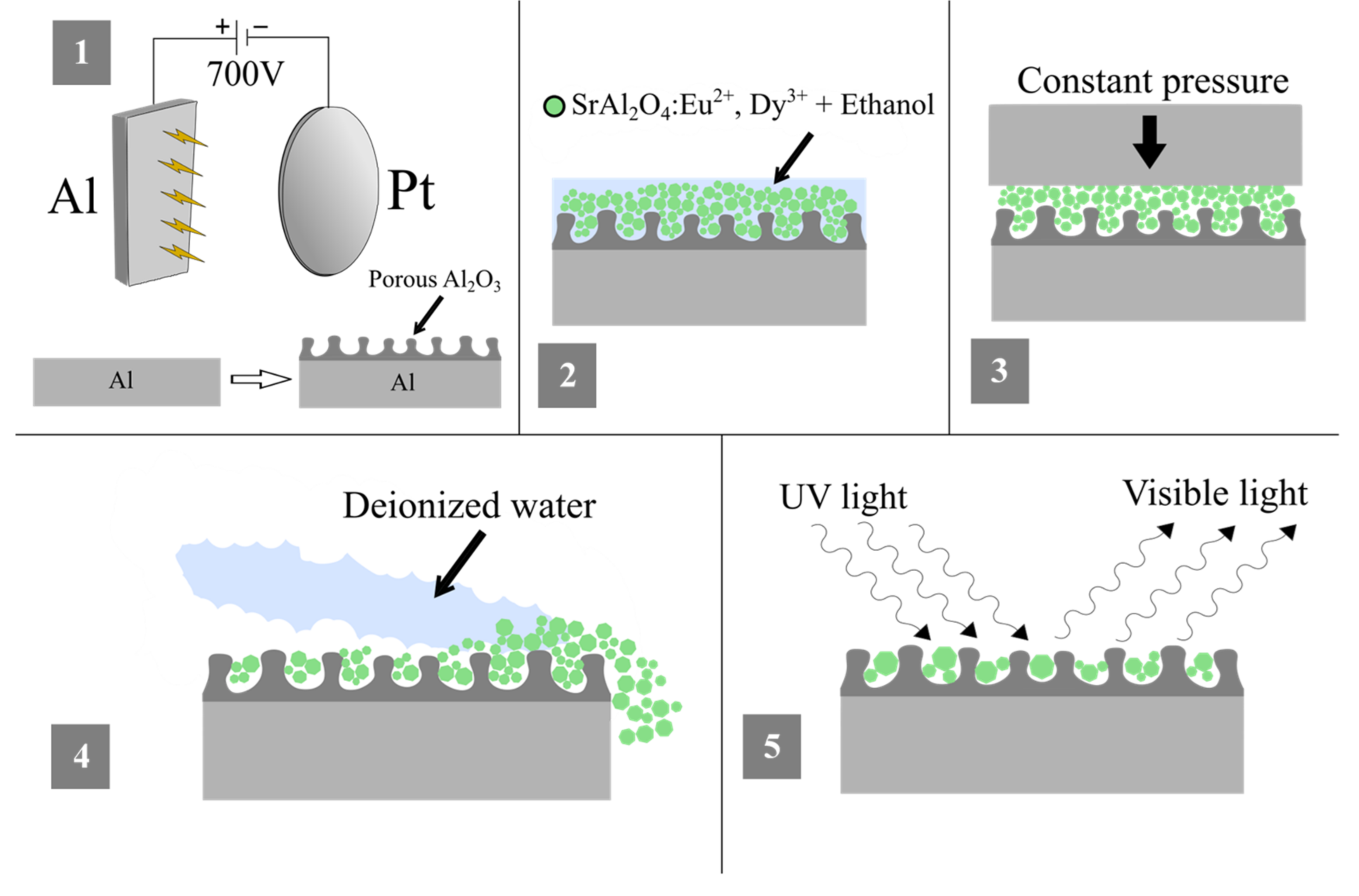
2.2. Synthesis
2.3. Analysis Methods
3. Results and Discussion
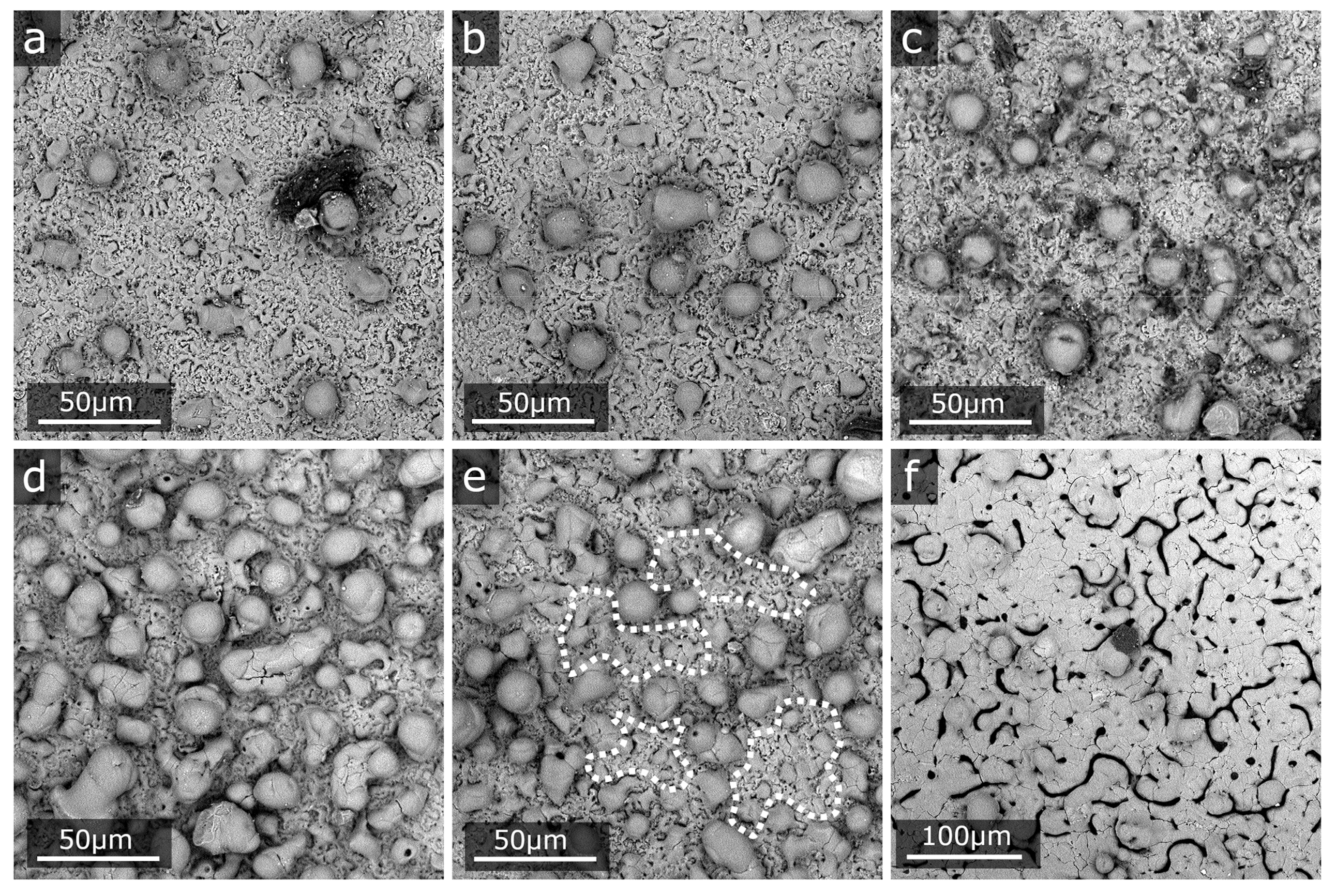
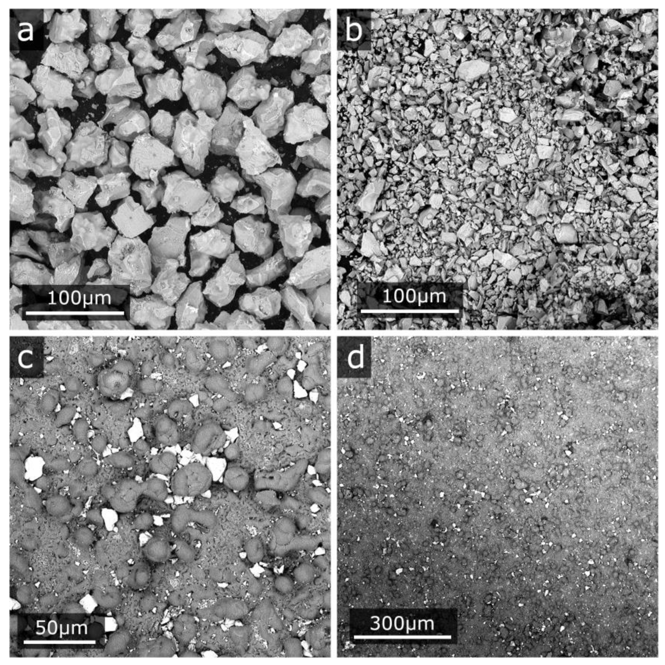
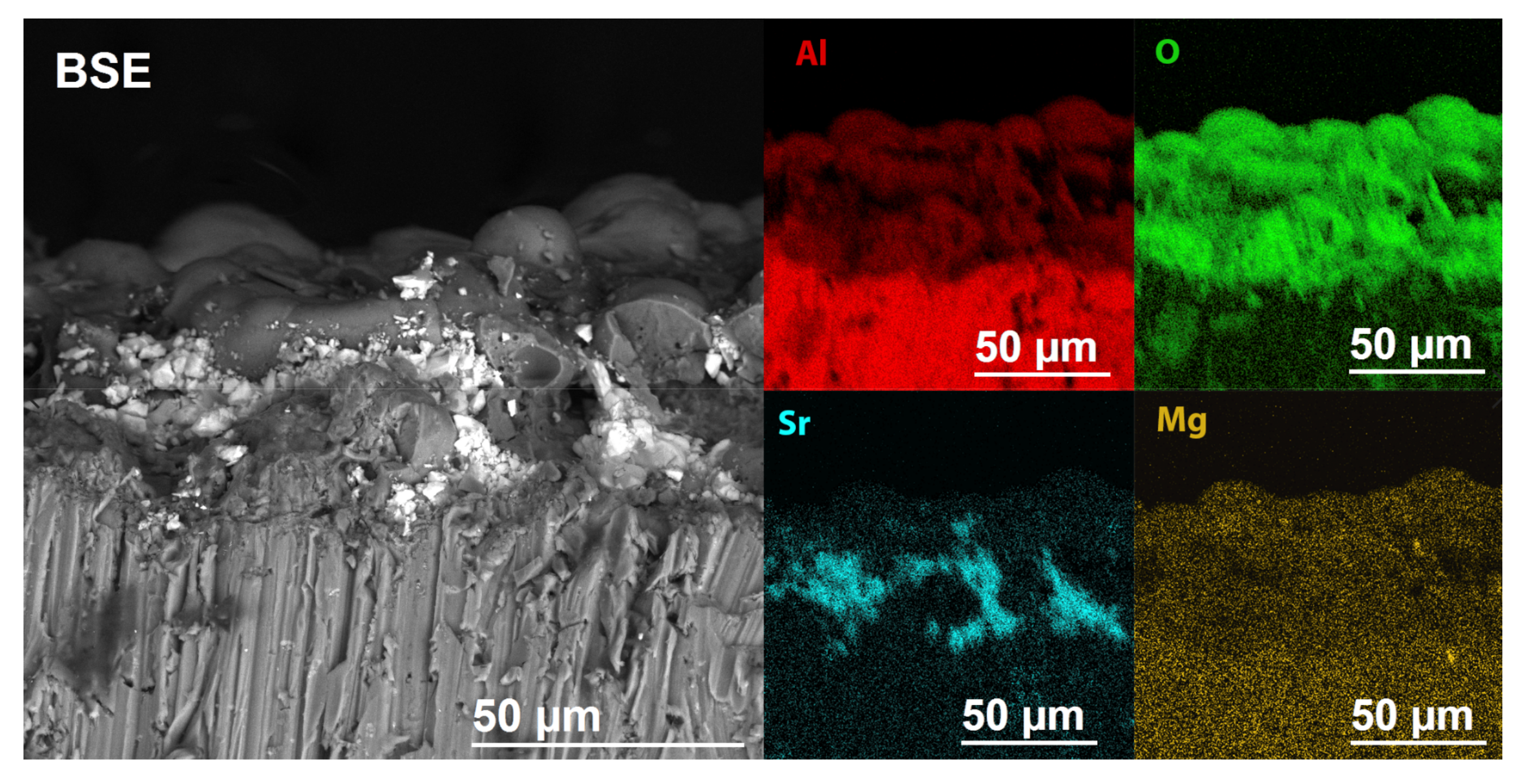
3.1. Structure and Morphology
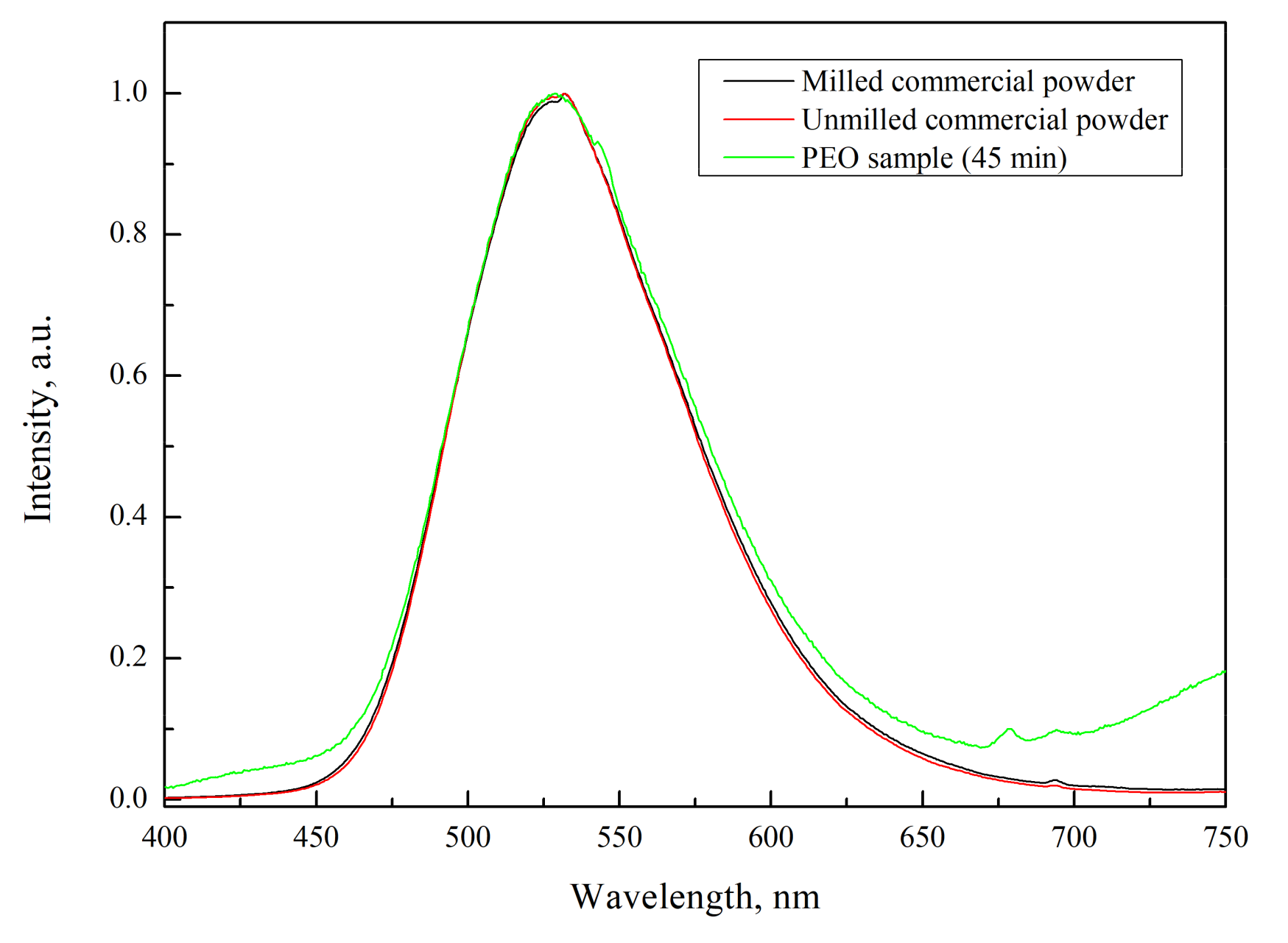
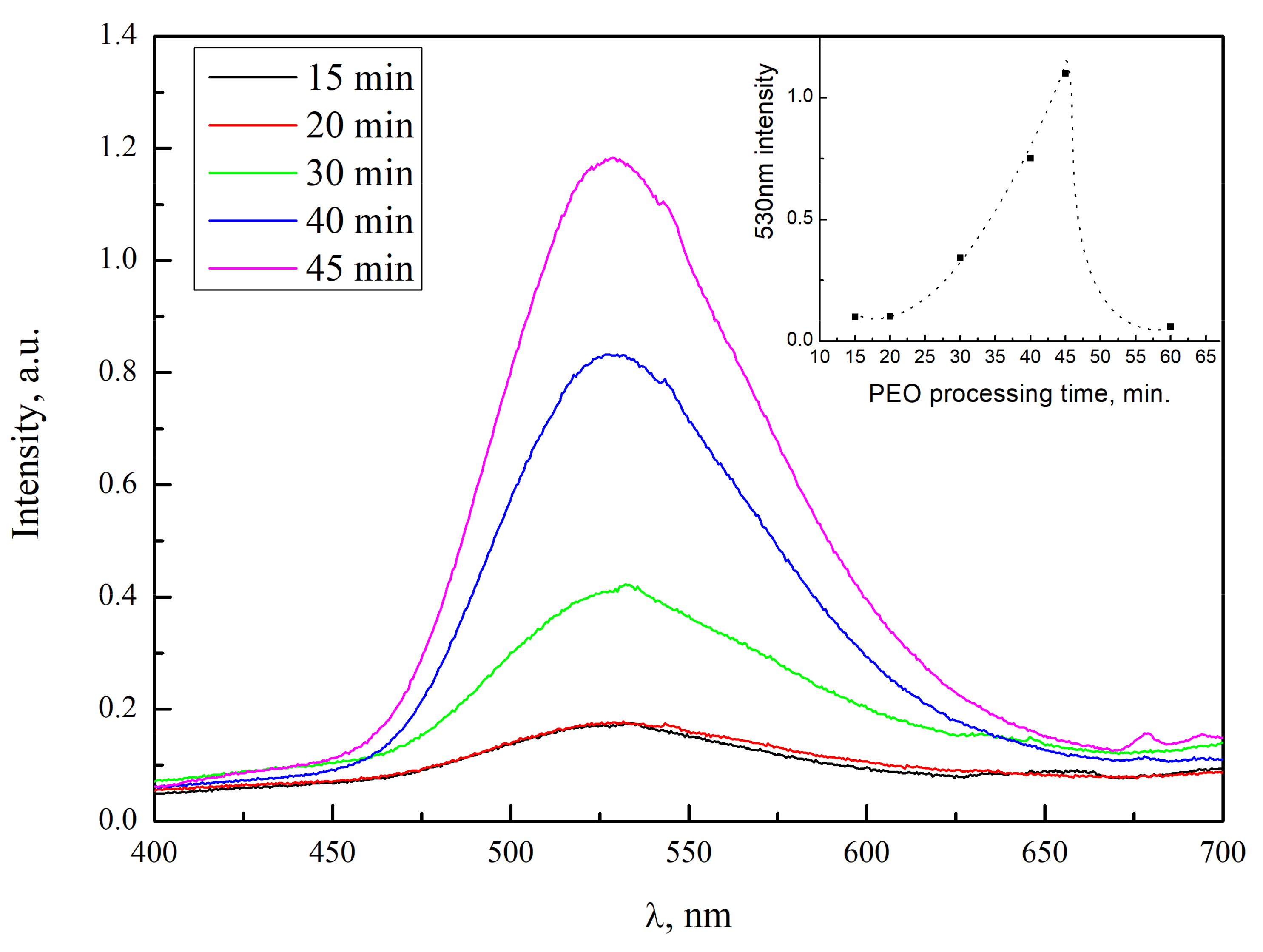
3.2. Luminescence
4. Conclusions
Author Contributions
Funding
Conflicts of Interest
References
- Shionoya, S.; Yen, W.M. Phosphor Handbook, 1st ed.; CRC Press LLC: Boca Raton, FL, USA, 1999; pp. 655–658. [Google Scholar]
- Lange, H. Luminescent europium activated strontium aluminate. US Patent US3294699A, 27 December 1966. [Google Scholar]
- Matsuzawa, T. A New Long Phosphorescent Phosphor with High Brightness, SrAl2O4:Eu2+,Dy3+. J. Electrochem. Soc. 1996, 143, 2670. [Google Scholar] [CrossRef]
- Haranath, D.; Shanker, V.; Chander, H.; Sharma, P. Studies on the decay characteristics of strontium aluminate phosphor on thermal treatment. Mater. Chem. Phys. 2003, 78, 6–10. [Google Scholar] [CrossRef]
- Lv, H.; Pan, Z.; Wang, Y. Synthesis and mechanoluminescent property of (Eu2+, Dy3+)-co-doped strontium aluminate phosphor by soft mechanochemistry-assisted solid-state method. J. Lumin. 2019, 209, 129–140. [Google Scholar] [CrossRef]
- Peng, T.; Yang, H.; Pu, X.; Hu, B.; Jiang, Z.; Yan, C. Combustion synthesis and photoluminescence of SrAl2O4:Eu,Dy phosphor nanoparticles. Mater. Lett. 2004, 58, 352–356. [Google Scholar] [CrossRef]
- Peng, T.; Huajun, L.; Yang, H.; Yan, C. Synthesis of SrAl2O4:Eu, Dy phosphor nanometer powders by sol–gel processes and its optical properties. Mater. Chem. Phys. 2004, 85, 68–72. [Google Scholar] [CrossRef]
- Chang, C.; Yuan, Z.; Mao, D. Eu2+ activated long persistent strontium aluminate nano scaled phosphor prepared by precipitation method. J. Alloys Compd. 2006, 415, 220–224. [Google Scholar] [CrossRef]
- Botterman, J.; Smet, P.F. Persistent phosphor SrAl2O4:Eu,Dy in outdoor conditions: saved by the trap distribution. Opt. Express 2015, 23, 868–881. [Google Scholar] [CrossRef]
- Lu, X.; Blawert, C.; Kainer, K.U.; Zhang, T.; Wang, F.; Zheludkevich, M.L. Influence of particle additions on corrosion and wear resistance of plasma electrolytic oxidation coatings on Mg alloy. Surf. Coatings Technol. 2018, 352, 1–14. [Google Scholar] [CrossRef]
- Sieber, M.; Simchen, F.; Morgenstern, R.; Scharf, I.; Lampke, T. Plasma Electrolytic Oxidation of High-Strength Aluminium Alloys—Substrate Effect on Wear and Corrosion Performance. Metals (Basel). 2018, 8, 356. [Google Scholar] [CrossRef]
- Rokosz, K.; Hryniewicz, T.; Gaiaschi, S.; Chapon, P.; Raaen, S.; Matýsek, D.; Dudek, Ł.; Pietrzak, K. Novel Porous Phosphorus–Calcium–Magnesium Coatings on Titanium with Copper or Zinc Obtained by DC Plasma Electrolytic Oxidation: Fabrication and Characterization. Materials (Basel) 2018, 11, 1680. [Google Scholar] [CrossRef]
- Apelfeld, A.V.; Ashmarin, A.A.; Borisov, A.M.; Vinogradov, A.V.; Savushkina, S.V.; Shmytkova, E.A. Formation of zirconia tetragonal phase by plasma electrolytic oxidation of zirconium alloy in electrolyte comprising additives of yttria nanopowder. Surf. Coatings Technol. 2017, 328, 513–517. [Google Scholar] [CrossRef]
- Yerokhin, A.L.; Nie, X.; Leyland, A.; Matthews, A.; Dowey, S.J. Plasma electrolysis for surface engineering. Surf. Coatings Technol. 1999, 122, 73–93. [Google Scholar] [CrossRef]
- Yerokhin, A.L.; Snizhko, L.O.; Gurevina, N.L.; Leyland, A.; Pilkington, A.; Matthews, A. Discharge characterization in plasma electrolytic oxidation of aluminium. J. Phys. D. Appl. Phys. 2003, 36, 2110–2120. [Google Scholar] [CrossRef]
- Rahmati, M.; Raeissi, K.; Toroghinejad, M.R.; Hakimizad, A.; Santamaria, M. Effect of Pulse Current Mode on Microstructure, Composition and Corrosion Performance of the Coatings Produced by Plasma Electrolytic Oxidation on AZ31 Mg Alloy. Coatings 2019, 9, 688. [Google Scholar] [CrossRef]
- Joost, W.J.; Krajewksi, P.E. Towards magnesium alloys for high-volume automotive applications. Scr. Mater. 2017, 128, 107–112. [Google Scholar] [CrossRef]
- Huda, Z.; Taib, N.I.; Zaharinie, T. Characterization of 2024-T3: An aerospace aluminum alloy. Mater. Chem. Phys. 2009, 113, 515–517. [Google Scholar] [CrossRef]
- Bouali, A.C.; Straumal, E.A.; Serdechnova, M.; Wieland, D.C.F.; Starykevich, M.; Blawert, C.; Hammel, J.U.; Lermontov, S.A.; Ferreira, M.G.S.; Zheludkevich, M.L. Layered double hydroxide based active corrosion protective sealing of plasma electrolytic oxidation/sol-gel composite coating on AA2024. Appl. Surf. Sci. 2019, 494, 829–840. [Google Scholar] [CrossRef]
- Lu, X.; Chen, Y.; Blawert, C.; Li, Y.; Zhang, T.; Wang, F.; Kainer, K.U.; Zheludkevich, M. Influence of SiO2 Particles on the Corrosion and Wear Resistance of Plasma Electrolytic Oxidation-Coated AM50 Mg Alloy. Coatings 2018, 8, 306. [Google Scholar] [CrossRef]
- Akatsu, T.; Yamada, Y.; Hoshikawa, Y.; Onoki, T.; Shinoda, Y.; Wakai, F. Multifunctional porous titanium oxide coating with apatite forming ability and photocatalytic activity on a titanium substrate formed by plasma electrolytic oxidation. Mater. Sci. Eng. C 2013, 33, 4871–4875. [Google Scholar] [CrossRef]
- Grigorjeva, L.; Millers, D.; Smits, K.; Zolotarjovs, A. Gas sensitive luminescence of ZnO coatings obtained by plazma electrolytic oxidation. Sensors Actuators A Phys. 2015, 234, 290–293. [Google Scholar] [CrossRef]
- Zolotarjovs, A.; Smits, K.; Laganovska, K.; Bite, I.; Grigorjeva, L.; Auzins, K.; Millers, D.; Skuja, L. Thermostimulated luminescence of plasma electrolytic oxidation coatings on 6082 aluminium surface. Radiat. Meas. 2019, 124, 29–34. [Google Scholar] [CrossRef]
- Park, S.Y.; Jo, C.I.; Choe, H.-C.; Brantley, W.A. Hydroxyapatite deposition on micropore-formed Ti-Ta-Nb alloys by plasma electrolytic oxidation for dental applications. Surf. Coat. Technol. 2016, 294, 15–20. [Google Scholar] [CrossRef]
- Kang, J.-I.; Son, M.-K.; Choe, H.-C.; Brantley, W.A. Bone-like apatite formation on manganese-hydroxyapatite coating formed on Ti-6Al-4V alloy by plasma electrolytic oxidation. Thin Solid Films 2016, 620, 126–131. [Google Scholar] [CrossRef]
- Smits, K.; Millers, D.; Zolotarjovs, A.; Drunka, R.; Vanks, M. Luminescence of Eu ion in alumina prepared by plasma electrolytic oxidation. Appl. Surf. Sci. 2015, 337, 166–171. [Google Scholar] [CrossRef]
- Stojadinović, S.; Tadić, N.; Vasilić, R. Photoluminescence of Sm2+/Sm3+ doped Al2O3 coatings formed by plasma electrolytic oxidation of aluminum. J. Lumin. 2017, 192, 110–116. [Google Scholar] [CrossRef]
- Bite, I.; Krieke, G.; Zolotarjovs, A.; Laganovksa, K.; Liepina, V.; Smits, K.; Auzins, K.; Grigorjeva, L.; Millers, D.; Skuja, L. Novel method of phosphorescent strontium aluminate coating preparation on aluminum. Mater. Des. 2018, 160, 794–802. [Google Scholar] [CrossRef]
- Martin, J.; Leone, P.; Nominé, A.; Veys-Renaux, D.; Henrion, G.; Belmonte, T. Influence of electrolyte ageing on the Plasma Electrolytic Oxidation of aluminium. Surf. Coat. Technol. 2015, 269, 36–46. [Google Scholar] [CrossRef]
- Liepina, V.; Millers, D.; Smits, K. Tunneling luminescence in long lasting afterglow of SrAl2O4:Eu,Dy. J. Lumin. 2017, 185, 151–154. [Google Scholar] [CrossRef]
- Aitasalo, T.; Dereń, P.; Hölsä, J.; Jungner, H.; Krupa, J.-C.; Lastusaari, M.; Legendziewicz, J.; Niittykoski, J.; Stręk, W. Persistent luminescence phenomena in materials doped with rare earth ions. J. Solid State Chem. 2003, 171, 114–122. [Google Scholar] [CrossRef]


| Sample No. | Voltage, V | Current Density, A/cm2 | Duration, Min | Powder Filling |
|---|---|---|---|---|
| P15N | 700 | 0.18 | 15 | No |
| P20N | 20 | |||
| P30N | 30 | |||
| P40N | 40 | |||
| P45N P60N | 4560 | |||
| P15Y | 700 | 0.18 | 15 | Yes |
| P20Y | 20 | |||
| P30Y | 30 | |||
| P40Y | 40 | |||
| P45Y | 45 | |||
| P60Y | 60 |
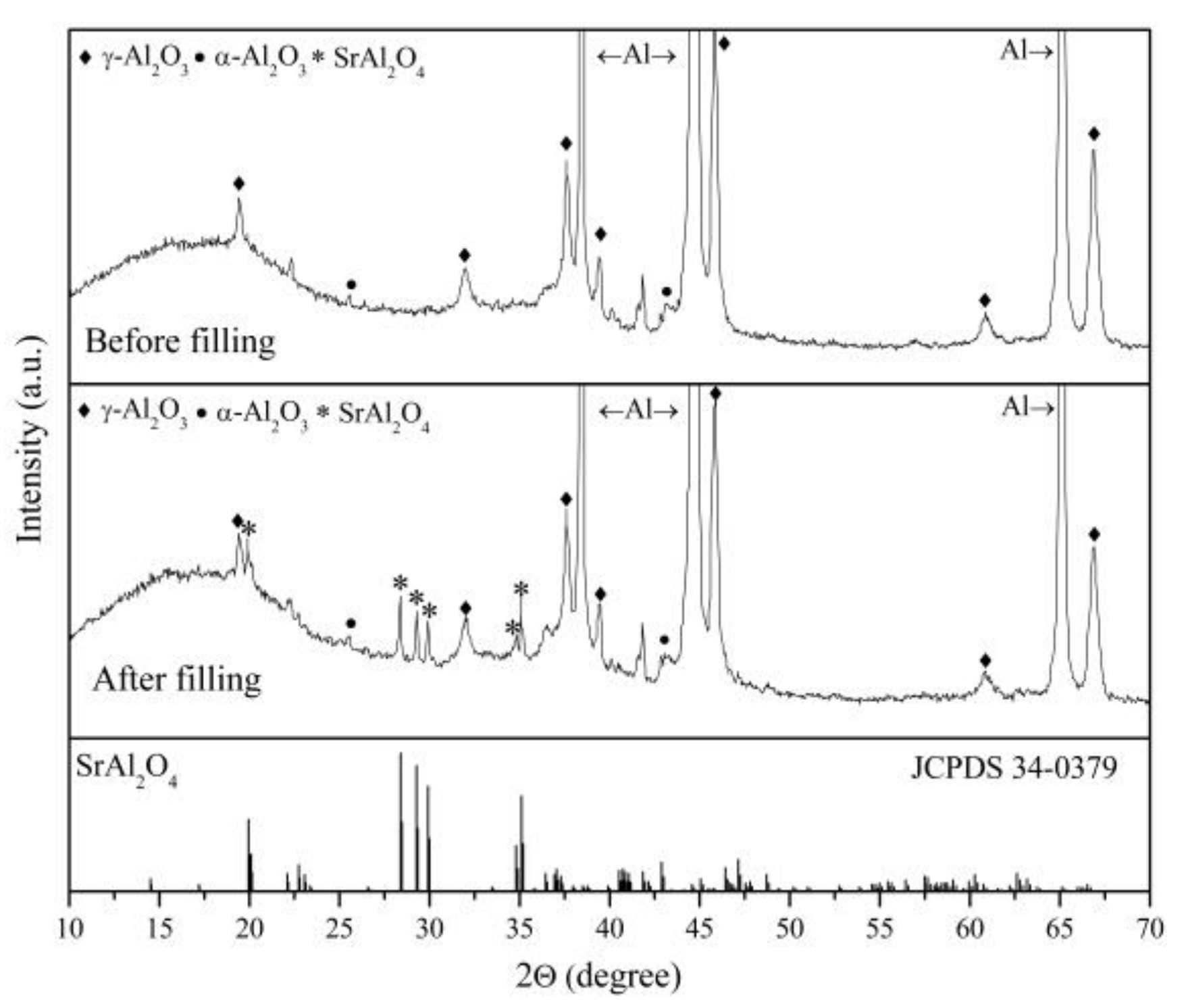
| Sample Name | γ-Al2O3 | α-Al2O3 | SrAl2O4 |
|---|---|---|---|
| P15N | X | - | - |
| P20N | X | - | - |
| P30N | X | - | - |
| P40N | X | X | - |
| P45N | X | X | - |
| P60N | X | X | - |
| P15Y | X | - | - |
| P20Y | X | - | - |
| P30Y | X | X | - |
| P40Y | X | X | X |
| P45Y | X | X | X |
| P60Y | X | X | - |
© 2019 by the authors. Licensee MDPI, Basel, Switzerland. This article is an open access article distributed under the terms and conditions of the Creative Commons Attribution (CC BY) license (http://creativecommons.org/licenses/by/4.0/).
Share and Cite
Auzins, K.; Zolotarjovs, A.; Bite, I.; Laganovska, K.; Vitola, V.; Smits, K.; Millers, D. Production of Phosphorescent Coatings on 6082 Aluminum Using Sr0.95Eu0.02Dy0.03Al2O4-δ Powder and Plasma Electrolytic Oxidation. Coatings 2019, 9, 865. https://doi.org/10.3390/coatings9120865
Auzins K, Zolotarjovs A, Bite I, Laganovska K, Vitola V, Smits K, Millers D. Production of Phosphorescent Coatings on 6082 Aluminum Using Sr0.95Eu0.02Dy0.03Al2O4-δ Powder and Plasma Electrolytic Oxidation. Coatings. 2019; 9(12):865. https://doi.org/10.3390/coatings9120865
Chicago/Turabian StyleAuzins, Krisjanis, Aleksejs Zolotarjovs, Ivita Bite, Katrina Laganovska, Virginija Vitola, Krisjanis Smits, and Donats Millers. 2019. "Production of Phosphorescent Coatings on 6082 Aluminum Using Sr0.95Eu0.02Dy0.03Al2O4-δ Powder and Plasma Electrolytic Oxidation" Coatings 9, no. 12: 865. https://doi.org/10.3390/coatings9120865
APA StyleAuzins, K., Zolotarjovs, A., Bite, I., Laganovska, K., Vitola, V., Smits, K., & Millers, D. (2019). Production of Phosphorescent Coatings on 6082 Aluminum Using Sr0.95Eu0.02Dy0.03Al2O4-δ Powder and Plasma Electrolytic Oxidation. Coatings, 9(12), 865. https://doi.org/10.3390/coatings9120865