Article

Modeling and Analysis of PV System with Fuzzy Logic MPPT Technique for a DC Microgrid under Variable Atmospheric Conditions

by
Vasantharaj Subramanian
1,
Vairavasundaram Indragandhi
1,
Ramya Kuppusamy
2 and
Yuvaraja Teekaraman
3,*
1
School of Electrical Engineering, Vellore Institute of Technology, Vellore City 632014, India
2
Department of Electrical and Electronics Engineering, Sri Sairam College of Engineering, Bangalore City 562106, India
3
MOBI-Mobility, Logistics and Automotive Technology Research Centre, Vrije Universiteit Brussel, Ixelles, 1050 Brussels, Belgium
*
Author to whom correspondence should be addressed.
Electronics 2021, 10(20), 2541; https://doi.org/10.3390/electronics10202541
Submission received: 17 September 2021 / Revised: 6 October 2021 / Accepted: 14 October 2021 / Published: 18 October 2021

Abstract

:
Due to the easiness of setup and great energy efficiency, direct current (DC) microgrids (MGs) have become more common. Solar photovoltaic (PV) and fuel cell (FC) systems drive the DC MG. Under varying irradiance and temperature, this work proposes a fuzzy logic controller (FLC) based maximum power point tracking (MPPT) approach deployed to PV panel and FC generated boost converter. PV panels must be operated at their maximum power point (MPP) to enhance efficiency and shorten the system’s payback period. There are different kinds of MPPT approaches for using PV panels at that moment. Still, the FLC-based MPPT approach was chosen in this study because it responds instantaneously to environmental changes and is unaffected by circuit parameter changes. Similarly, this research proposes a better design strategy for FLC systems. It will improve the system reliability and stability of the response of the system. An FLC evaluates PV and FC via DC–DC boost converters to obtain this enhanced response time and accuracy.

1. Introduction

Energy usage on a global scale is gradually increasing. Conventional energy sources produce greenhouse gases. As a result, non-conventional energy sources like solar PV were created since they are clean, abundant in nature, cost-effective, and widely used. The majority of rural populations lack access to safe and reliable energy. Rural electrification had a comparatively high initial investment cost. Installing DC MGs based on renewable energy sources (RESs) such as solar PV and FC with ESS [1] is simple and cost-effective. Due to their ease of interface with distribution generators (DG) without the requirement for interlinking AC/DC and DC/AC transformation stages and the lack of reactive power and problematic frequency considerations, DC MGs are becoming increasingly popular in the current climate. For integrating DGs with DC MGs, DC/DC converters are essential. Buck converters, boost converters, and buck–boost converters are the three types of DC/DC converters commonly used. This DC MG also employs bi-directional DC/DC converters to ensure high dependability and load power delivery.
The study of PV generation technologies has attracted an increasing number of academics [2,3]. As the DC power generated by PV cells must be transformed into AC power before being used, an inverter is required. The transformerless inverter is frequently employed because of its lightweight, small size, and inexpensive cost [4,5]. MPPT is commonly performed in the DC–DC section to increase PV system efficiency, and in the DC–AC section, DC power is converted to AC power for grid injection. Similarly, ultra-capacitors are preferred with battery combinations [6,7] because low power density batteries cannot adjust for rapid power fluctuations. This work uses a fuzzy-based MPPT [8,9] technique to achieve MPPT [10] of solar PV and FC at the DC-link that includes all hybrid power (PV–FC) with battery and ultra-capacitor power. A distributed RES, ESS, and DC load with a voltage source converter connected to the grid is shown in Figure 1. DC MGs provide several advantages over AC MGs, including increased efficiency, reliability, and reduced pollution. They do not have to worry about frequency or reactive power, making connecting to DC micro sources simple.
DC loads are frequently connected to AC terminals because of the lack of independent DC supply at the consumer’s site. Multiple conversions emerge from the customization of AC power with converters for diverse DC load requirements [11]. The conversion losses and harmonics created by converters are steadily increasing, contaminating the electrical grid. The average power loss due to these conversion procedures is 10% to 30% [12].
The objective of the intelligent hybrid technique is to improve the system’s reliability by managing unpredictability, intermittency, and inadequacy of RESs [13,14]. Utilization and enhancement of RES are among the topics studied in renewable energy research. Consumption and advancement of renewable energies are among the topics studied in renewable energy research. PV, wind, FC, biomass, and small-scale hydraulic power generations give the perfect developing importance in the systems for generating green energy. An FC, which converts fuel directly into electricity via an electrochemical reaction, is considered among the sustainable new energy sources with the most significant growth potential.
Electrolysis is used in an electrolyzer in the FC to produce hydrogen gas [15]. Tanks made of metal hydride are more expensive and bulkier than gas tanks. Still, they are safer in the event of an accident, which is why they are so crucial for self-governing systems in isolated locations. This will allow renewable energy to be used in complementing settings with polybasic power adjustment capacity. The FC’s power output is not constant, and it varies substantially depending on humidity and ambient temperature. In FC, the relationship between voltage and current is non-linear, so there is only one operating point for an FC system that corresponds to maximum output in a certain condition. The MPP, on the other hand, varies depending on temperature and membrane water level, making it difficult to monitor the MPP. During various operational conditions, depending upon stack current and fuel flow, the MPPT algorithm optimizes fuel usage and tracks the MPP of an FC.
Hydrogen can be used as a transportation fuel [9] and medium to long-term energy storage. Hydrogen sub-systems are being integrated with RESs in recent years. An electrolyzer is a device that utilizes electrolysis to create hydrogen. Gas tanks and metal hydride tanks are still the most prevalent methods for storing hydrogen for RESs [16,17]. Metal hydride tanks need a larger initial expenditure, but the benefits include increased safety toward accidents, which is crucial for autonomous systems in remote regions. If hydrogen is to be used as a transportation fuel, a refueling mechanism is required. An FC is a device that uses hydrogen to generate power. The use of a hydrogen sub-system provides significant benefits over huge battery banks in the view of energy density and long-term storage.
The following is a breakdown of the structure of the study. Section 2 provides a full overview of the DC MG, while Section 3 discusses solar PV and FC mathematical modeling. The MPPT control technique of FLC to manage the DC bus voltage is explained in Section 4, and the simulation results are shown in Section 5. Section 6 depicts the conclusion and future scope of the research.

2. Literature Review

The DC MG [18] is viewed as a promising approach for synchronizing distributed generators (DGs) because it can handle various loads. For a DC MG having multiple loads, this research presents a source-side output impedance model and input impedance model on the load-side. The resulting small-signal impedance models are then put through a Nyquist principle on reliability analysis to see how load states affect the DC MG system’s damping performance and reliability constraints.
Zhangjie Liu [19] suggested the presence and reliability equilibrium of a DC MG with constant power loads (CPLs) and the necessary criteria. The proper requirements for a system’s stable equilibrium are defined, and a stabilizing strategy is proposed. They show that the presence of a stationary mapping increases and transforms the issue of non-linear equations optimally. The adequate requirement is less cautious than the previous results. By examining the eigenvalue of the Jacobian matrix, this method used the corresponding linearized model surrounding the equilibrium to determine the locally robust reliability criteria. These characteristics serve as a design guide for constructing dependable DC MGs.
Mahesh Srinivasan and Alexis Kwansinski [20] show how to build multilayer control mechanisms for DC MGs using CPLs as a load using a conceptual approach. The issues of connecting sources with a large voltage range, allowing any power source to be used, are discussed in this work. There are two levels to the control strategy. Droop-based primary controllers make up the lower level. This controller allows paralleled sources to share current and dampens limit cycle oscillations caused by steady power loads. At a higher level, a secondary controller compensates for voltage variations caused by the primary controller and controls the MGs voltage. It also keeps the present share that was established at the preliminary step. The equivalent circuit of converters is used to explain the stability conditions. Stability conditions for MGs of any size and converter architecture may be calculated using this method.
Using MPPT algorithms that are more widely used, these study models and evaluates them [21]. As a result of these algorithms, PV systems can be compared in terms of sensor count, execution ease, efficiency, and dynamic response to temperature and irradiance variances. Adaptive neuro-fuzzy interference system (ANFIS) is used to develop a custom artificial intelligence technique in this paper. The duty cycle of the DC–DC converter implemented in the circuit is predicted using solar irradiance and cell temperature. The recommended method is a fast-tracking algorithm with good accuracy and stability.
There are numerous approaches for achieving MPP, as well as numerous review publications. However, only a few articles had evaluated these methods from an economic or practical standpoint. M.A. Danandeh and S.M. Mousavi G [22] provides a review of MPPT strategies based on a complete and comparatively innovative grouping system, with a focus on method comparison. The output power obtained by PV panels varies with variations in temperature and radiation. Under varying temperature and radiation circumstances, it is critical to maintain the PV panel’s output voltage at the MPP.
An MPPT approach was established by Unal Yilmaz [23], FLC block is for adjusting the duty cycle of the DC–DC converter’s PWM applied switch (Mosfet). Under varied atmospheric conditions, the Matlab/Simulink (2019a, The Mathwork, Inc., Natick, MA, USA) application was utilized to compare the suggested method’s resilience to previous techniques like Perturb and Observe (P&O), Incremental Conductance (Inc. Cond.), and FLC approaches. When the test data are examined, it is discovered that the suggested MPPT approach improves MPP tracking capability while also reducing steady-state oscillations.
Unal Yilmaz [24] makes a case for fuzzy logic. Under fluctuating temperature and irradiance, the MPPT approach used a boost converter provided from a PV panel. The buck converter was given PI control to act as a charge controller. The PV’s voltage and current are non-linear, which are affected by factors such as temperature and irradiation. Variable climatic circumstances influence the voltage and current of PV panels, as well as the maximum possible power. PV panels must be operated at MPP to enhance efficiency and shorten the system’s payback period. Although there are several MPPT methods in the literature, the FLC MPPT methodology was adopted for this project since it reacts rapidly to changing environmental conditions and is undisturbed by circuit parameter changes.
Based on the inversion method, this study discusses theory [25] and a new strategy for fault detection and isolation (FDI) in DC–DC converters. The suggested technique consists of inversion-based fault estimation and change detection algorithms that have been tailored to the needs of power converters. Using the inverse model of a switched linear system, we created a real-time FDI approach that identifies and separates unexpected fluctuations at unexpected time moments. A smoothing process is implemented to lessen the impact of unidentified disturbances at the inverse model’s outputs. Once the problem has been identified, a particular FLC technique has been created for isolating the four categories of faults: switch, voltage, and current sensor, and capacitor.
MG systems use a variety of energy sources [26], but the most common is PV, which converts solar radiation into electrical energy. However, the PV system’s usage time is restricted. Thus it requires a backup energy source to meet the load’s energy requirements whenever the sun is not shining. Most PV systems employ MPPT, which employs an algorithm to maximize PV power. The usage of MPPT in a PV system has a good influence in that it can enhance power efficiency on MG. Still, it can also produce issues like variable voltage and voltage exceeding the DC bus voltage. As a result, steady voltage control is required to maintain a constant voltage on the DC bus at a particular step input. As a result, FLC will be proposed in this research to keep the DC bus voltage constant.
RES has a finite amount of power and is therefore inconvenient. To prevent battery depletion and maintain the state of charge (SOC) at acceptable levels, battery-based ESS [27] have constraints in their charging and discharging capacities. The battery regulates the power imbalance between RES and loads. Yet, in extreme stages at which SOC is low, load shedding is essential. In this research, an FLC is developed to regulate the power flow of the PV unit and the battery to fully utilize the available PV power to meet the load fully. It regulates the PV’s power output and ensures that the battery’s SOC and charging/discharging power remain within acceptable limits despite load fluctuations. Whenever the batteries cannot control the MG power flow, load shedding of low priority loads was also employed.
Under different dynamic situations, the PV system is proposed in the MG system with the FC and battery bank [28]. FLC is also recommended for maintaining grid stability and regulating bus voltage. To establish the effectiveness of the suggested control mechanisms, the system was validated with multiple dynamic scenarios such as 50% variations in irradiance, AC and DC loads, overloading conditions, and the battery bank working whenever the variation in FC is noted. The modeling results suggest that the recommended fuzzy-based strategy outperforms the proposed energy storage devices in terms of dynamic performance.
To improve system efficiency and achieve the steady-state of power output, Meng Hui Wang offers [29] an extended sliding mode controller (ESMC) for MPPT of FCs. In this research, a 200-watt PEMFC serves as the experimental platform. The ESMC’s tracking speed is 0.95 s, and the booster efficiency is 94.5 percent, although both are faster than other standard MPPT systems. A variety of significant technologies for RESs are demonstrated in this study.
The MG provides power, hydrogen as a transportation fuel, and potable water via desalination to meet the needs of electricity, transportation, and water. Initially, the equipment was managed and controlled using an ON/OFF strategy. A new approach [30] based on fuzzy logic was developed and tested through simulation in this paper. The FC, desalination unit, and electrolyzer unit are the instruments being managed. A design tool based on TRNSYS 16, Matlab, GenOpt 2.0, and TRNOPT was built utilizing the particle swarm optimization (PSO) approach. Two MGs were built using this tool in order to evaluate the efficiency of FLEMS with the ON/OFF technique. The results show that FLEMS utilizes the obtainable amount of energy in the system better and the sizes of the components are, thus, significantly reduced. The comparative analysis of the literature study is shown in Table 1. From this comparative analysis, the proposed fuzzy controller produces enhanced response time and accuracy. It will improve the system reliability and stability of the response of the system.

3. Mathematical Model of Solar PV and Fuel Cell

For PV and FC, the mathematical equations are developed and created using Matlab/Simulink, as shown below:

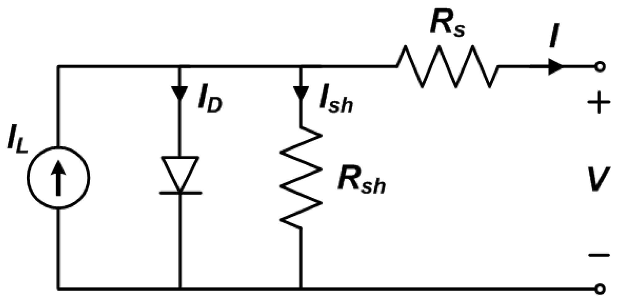
3.1. Modelling of Solar PV

PV cells are electrical devices that transform solar energy into electrical power using a semiconducting semiconductor that exhibits the photovoltaic effect.
Photovoltaic cells are used to quantify electrical variables such as current, voltage, and resistance as they change in response to sunlight. The analogous circuit of a solar cell is shown in Figure 2. When an electron collides with another electron in its bound state, electron conduction occurs, and these electrons are powered by the base energy generated by the semiconductor’s bandgap. A diode, a light-generating source, and a resistor are all linked in parallel in the equivalent circuit of the PV [31,32] modules. The following Equations (1)–(3) explain the mathematical equations for modeling solar cells.
I = I L I D [ exp ( qV k b TA ) 1 ]
  I sh = [ V + ( I R s ) ] R p  
I L = I rr [ I sc + k i ( T op T ref ) ]  
where, IL = load current; ID = diode current; Irr = saturation current at Tref; Isc = short-circuit current at reference condition; Tref = reference temperature; T = temperature (°C); q = electron charge; ki = short-circuit temperature coefficient; Ish = shunt resistance current; Rsh = Shunt Resistance; kb = open-circuit voltage temperature coefficient.

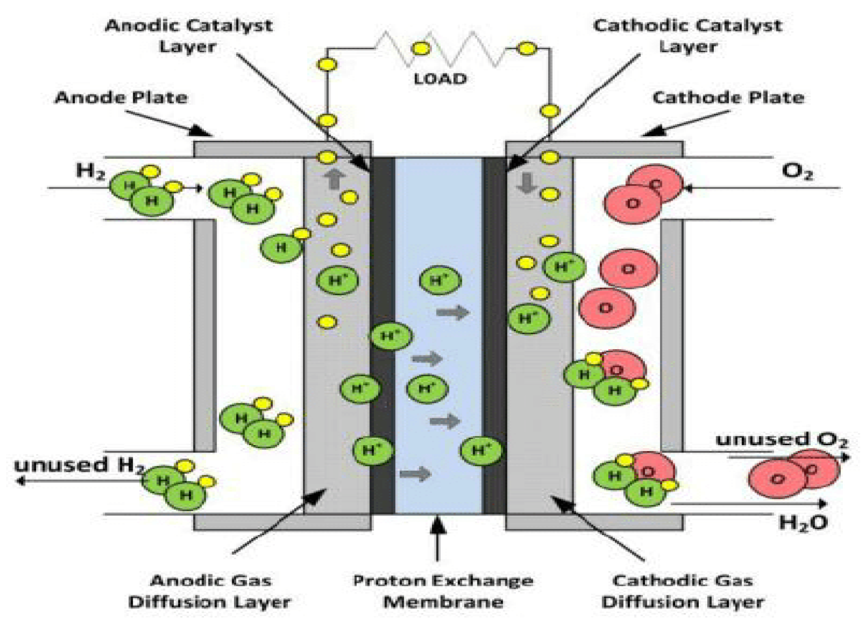
3.2. FC Mathematical Model

Proton exchange membrane (PEM) [33,34,35], catalytic layer (CL), gas diffusion layer (GDL), gas channel (GC), and current collector (CC) of both anode and cathode make up the FC. The proton exchange membrane fuel cell is depicted in Figure 3. (PEMFC).

3.2.1. Model Equations of FC

Mass, thermal energy, momentum, species, and charge are included in the FC basic model. This FC model operates based on five equations. These equations are combined to produce an electrochemical process that expresses reaction kinetics and electro-osmotic drag during the polymer electrolyte process. The equations express the FC model in vector form as follows.

3.2.2. Continuity Equation

Carbon fiber or carbon cloth is used to make the electrodes in the FC. The reactant gases are dispersed throughout the CL, and the electrodes are held in place by a porous material. Equation (4) gives the continuity equation for porosity with the aid of electrodes (ε).
( ε ρ t ) + · ( ε ρ U ) = 0
where ∇ = differential operator of a vector, ρ = liquid density, ε = porosity, U = floating speed vector.

3.2.3. Momentum Conservation

Equation (5) shows the Navier–Stokes equation and is designed for a Newtonian fluid.
( ( ε ρ U ) t ) + · ( ε ρ U 2 ) = ε p + ε F + · ( ε τ ) ε 2 μ U k
where ρ = pressure; τ = stress tensor; F = floating mass vector; μ = liquid viscidity degree; k = permeate ratio of the liquid by porous medium.

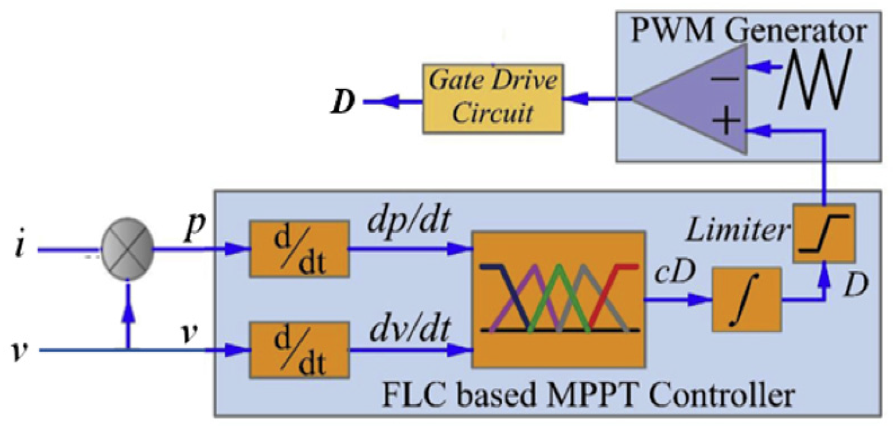
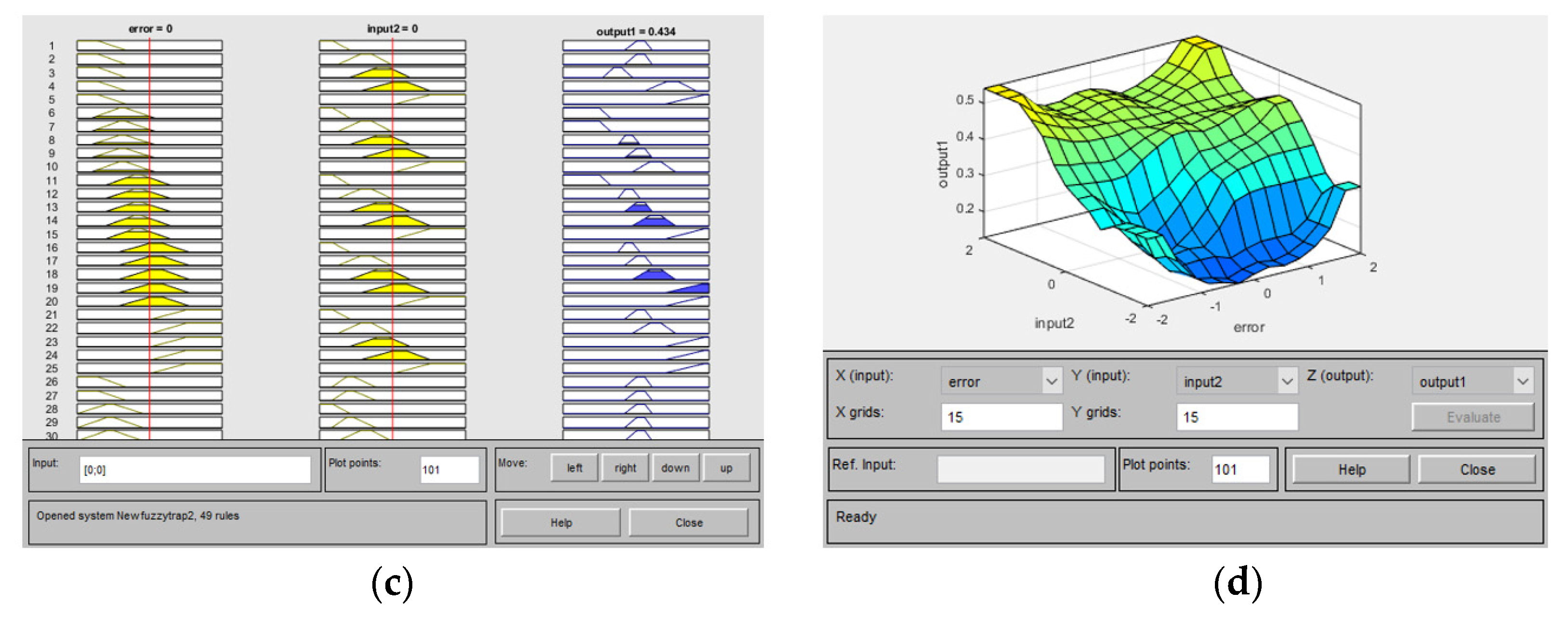
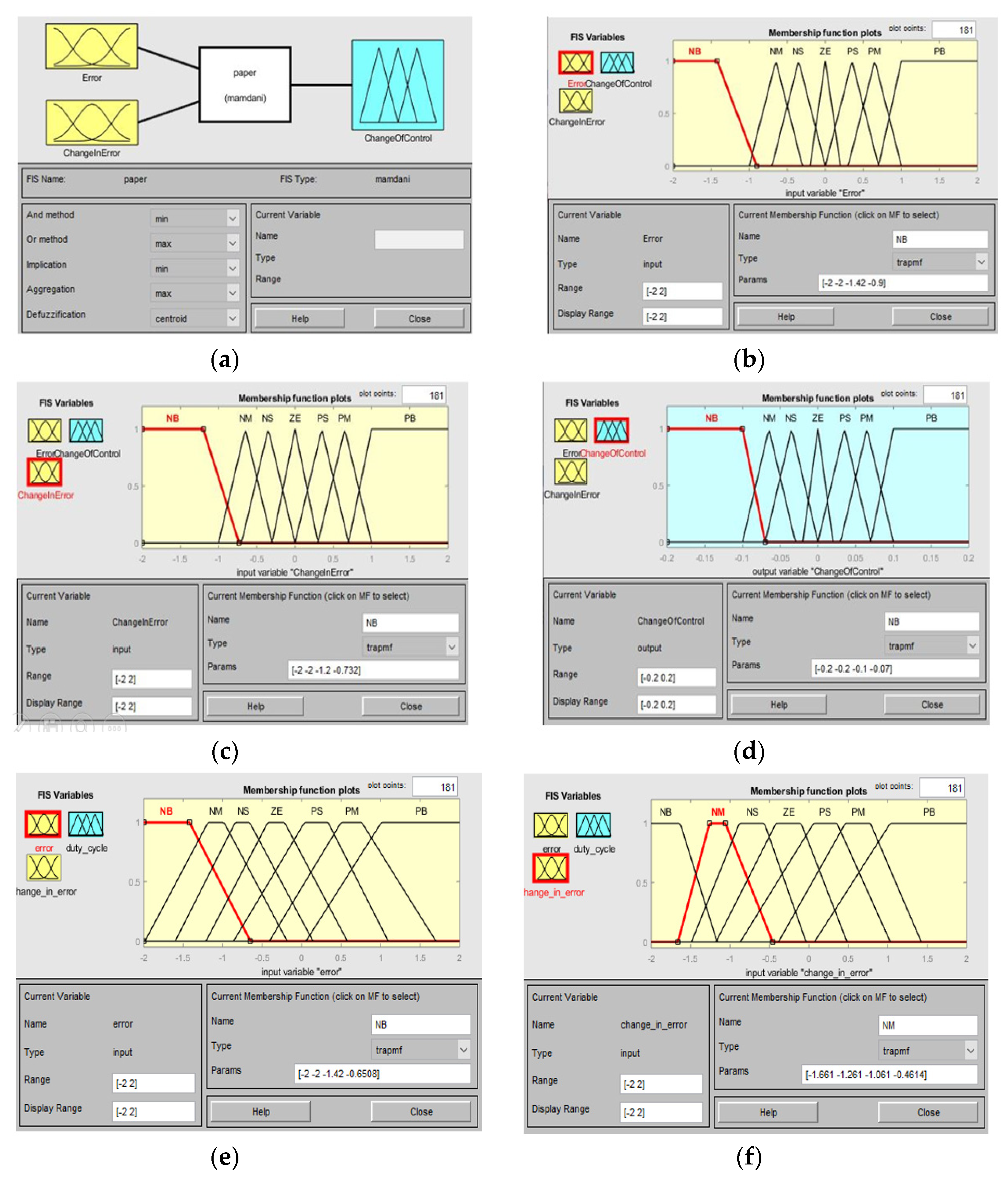
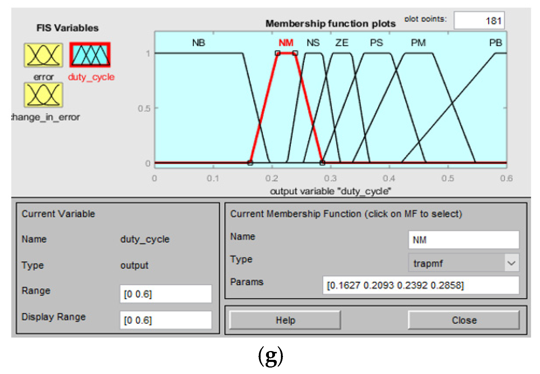
4. Fuzzy Logic Controller

The linguistic variables and their ranges are identified using major control factors, and the FLC [36,37,38,39] are then built using these control variables. For the impression to be formed, a human’s specific mind and knowledge are necessary. The proposed circuit of the DC MG with FLC is shown in Figure 4. An FLC-based MPPT controller and an FLC rule viewer and surface viewer for both triangular and trapezoidal membership function (MF) are depicted in Figure 5 and Figure 6. Consider the input variables error E (k) and change in error DE (k) while determining the fuzzy MFs (k). As a result of these input signals, linguistic variables are obtained. Change of control (Duty cycle D (k)) is the output of the fuzzy MF. With the usage of the intuition technique, a triangle MF was employed to determine the membership values of E (k) and DE (k) and for the same trapezoidal membership, values were also determined, which is shown in Figure 7. A triangular type membership function (MF) is proposed for an individual dominating fuzzy subset to identify any unique input. Seven fuzzy sets are measured for membership functions. Similarly, this triangular type MF is compared with trapezoidal type MF for the same input of duty cycle for the DC–DC boost converter. Table 2 proposes fuzzy rules for the hybrid (PV–FC) system. Figure 8 shows the Simulink model of Fuzzy logic MPPT controller.

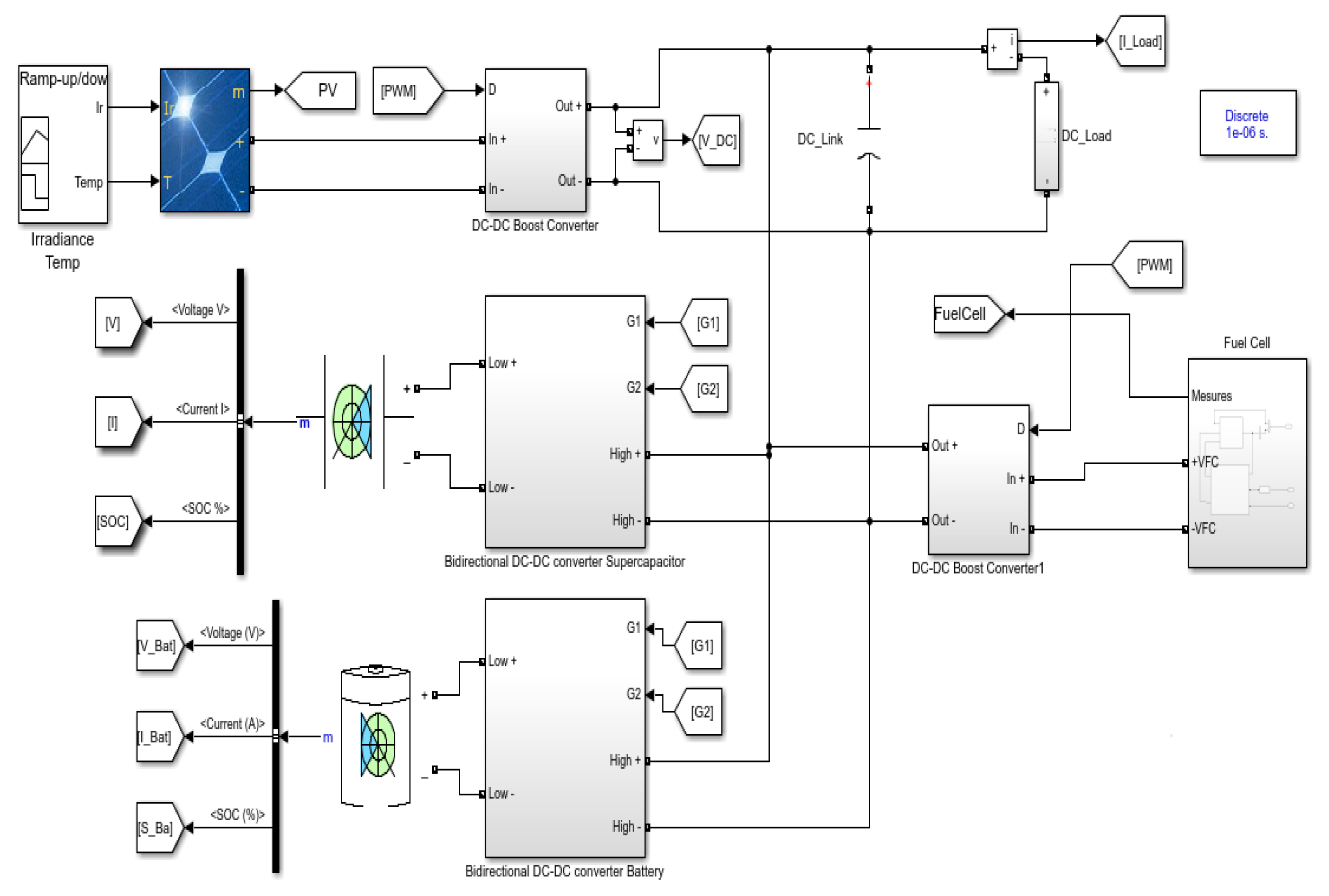
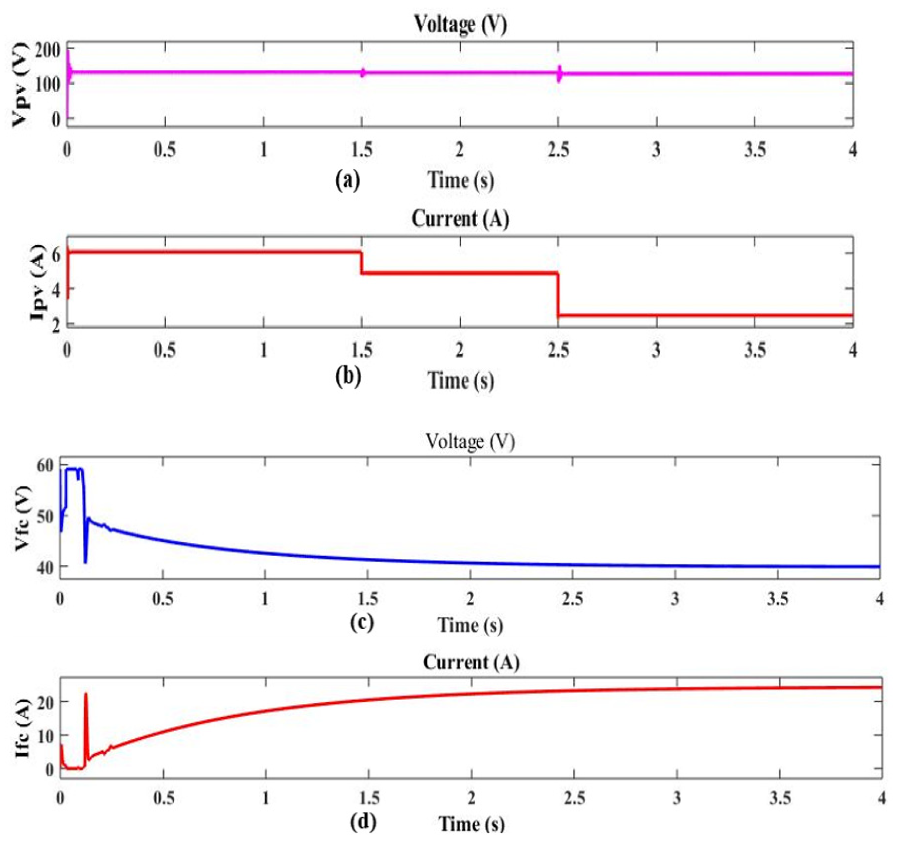
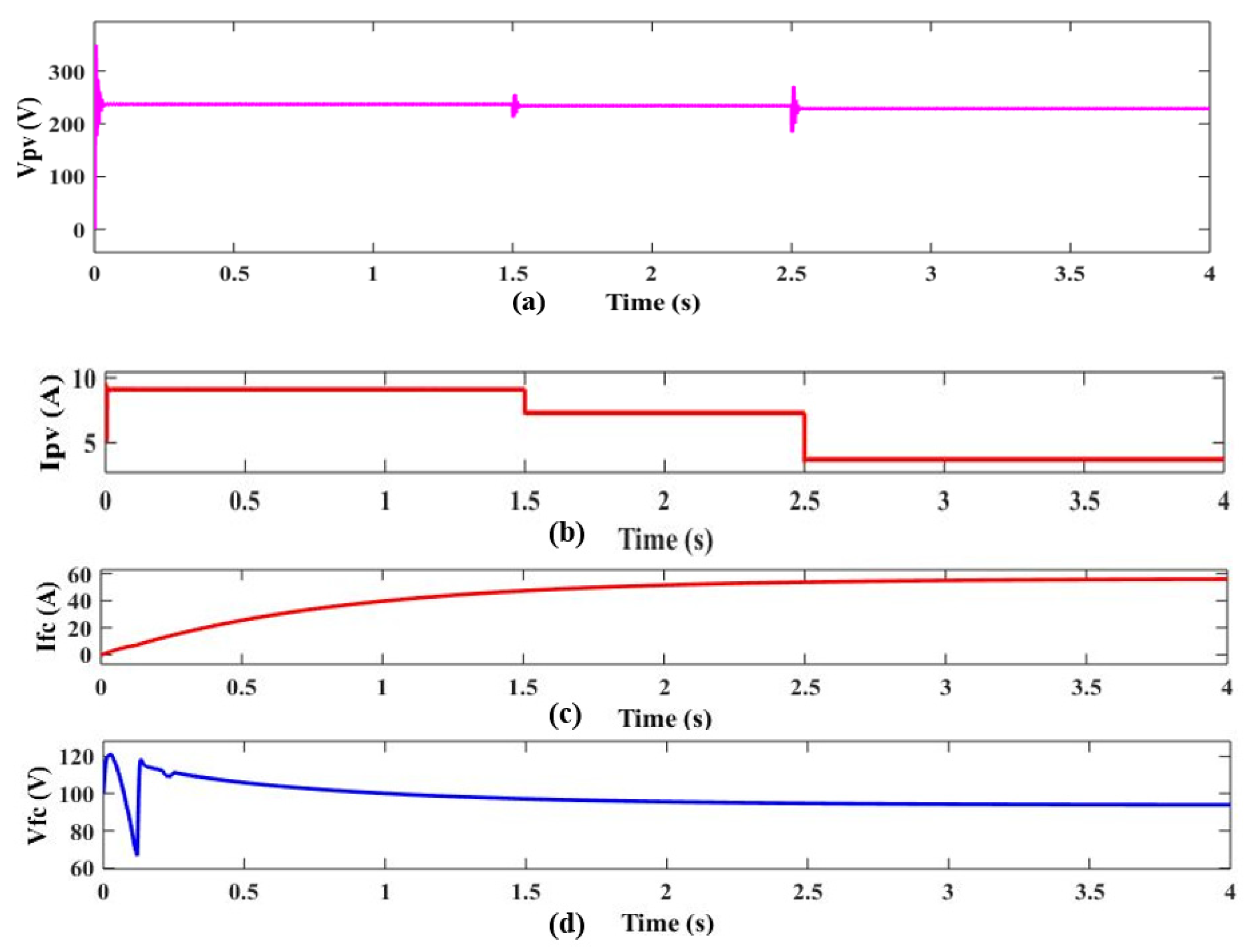
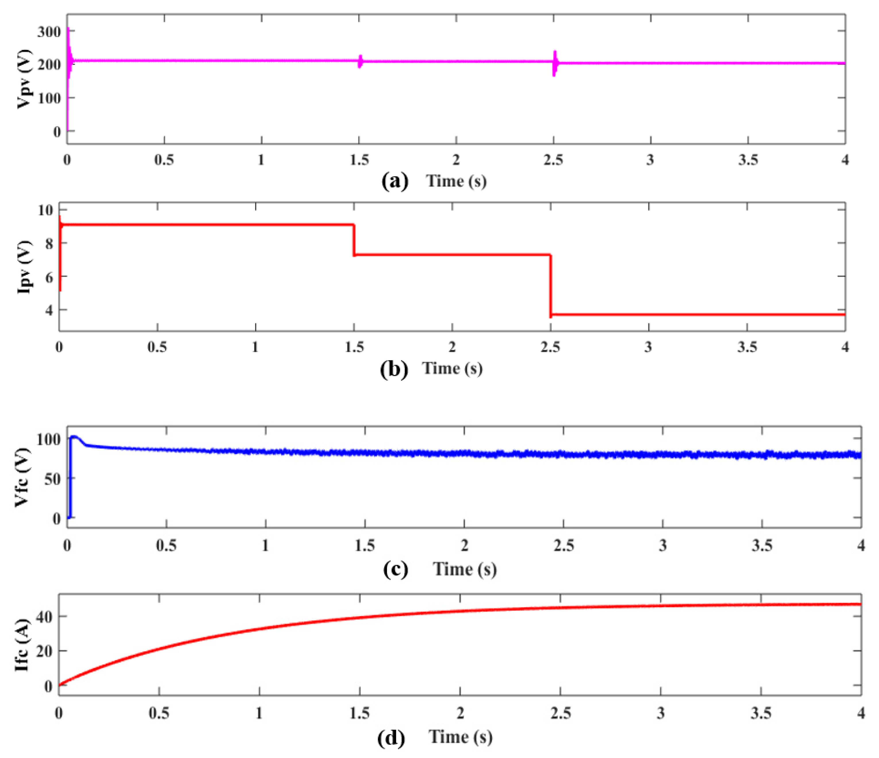
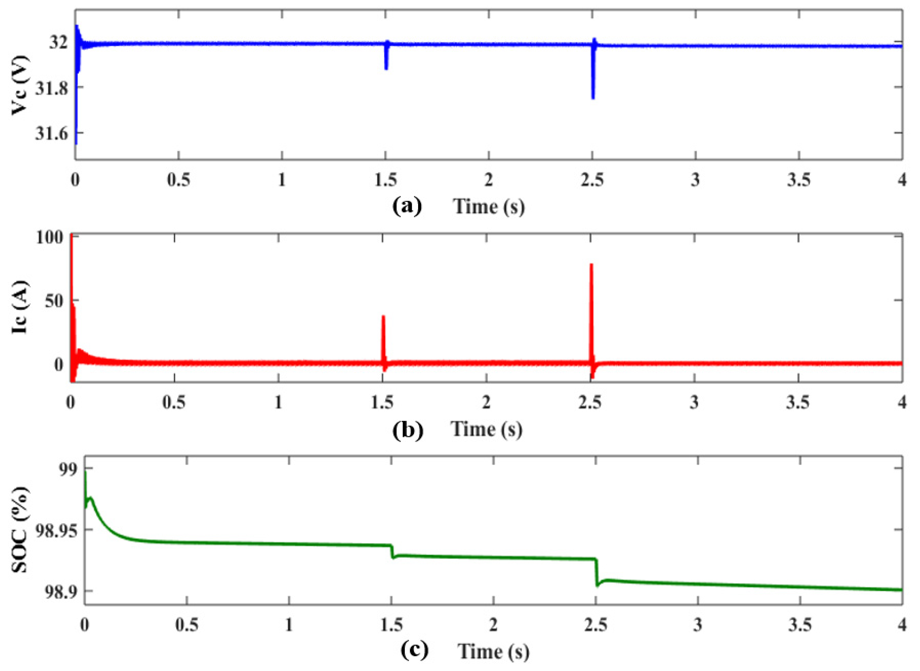
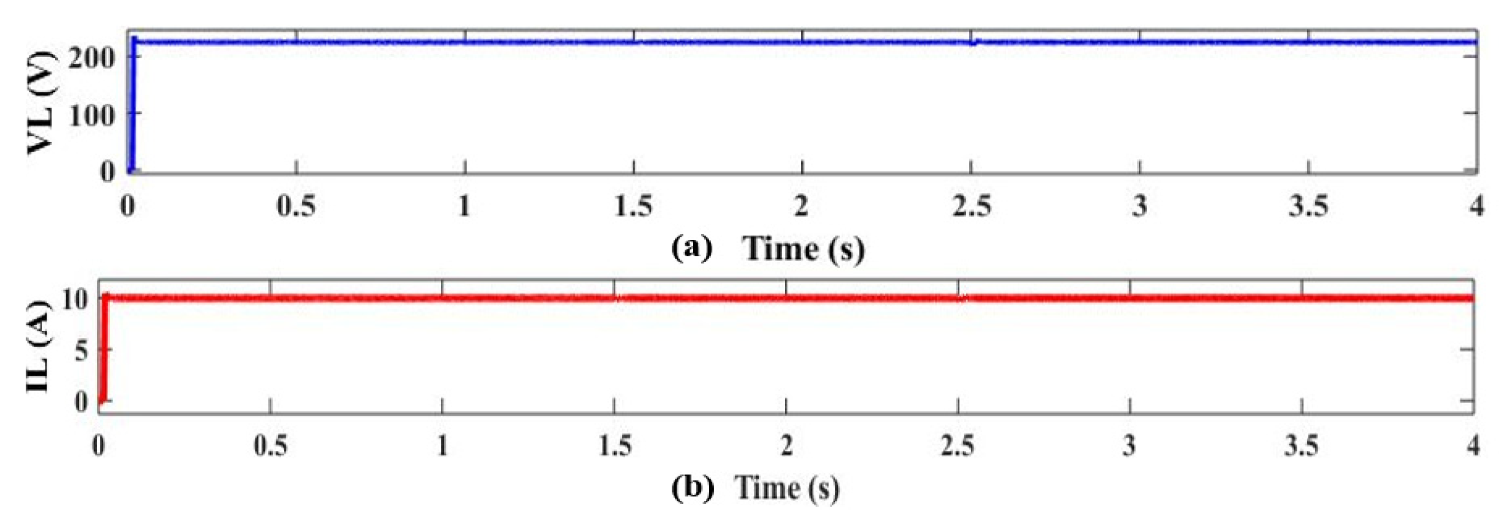
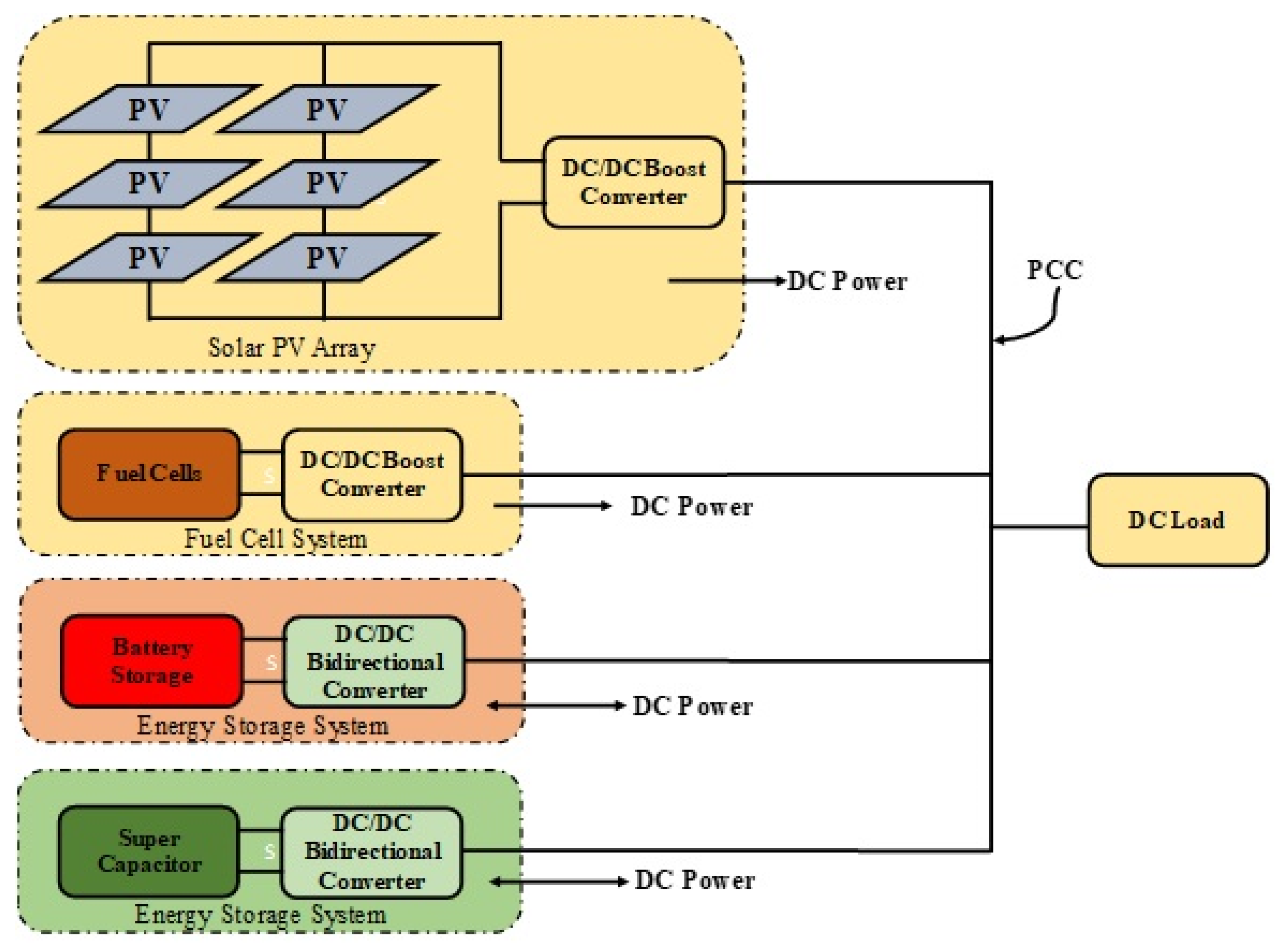
5. DC Microgrid Simulink Model

The hybrid DC MG Simulink model using MATLAB includes DC–DC boost converters, PV, FC, FLC-based MPPT technique, and resistive load. The MATLAB simulation software was used to create the suggested hybrid DC MG. Figure 9 depicts a MATLAB Simulink model of a hybrid DC microgrid. In contrast, Figure 10 depicts solar PV irradiance of 1000 W/m2 for t = 1.5 s, 800 W/m2 for t = 2.5 s, and 400 W/m2 for t = 4 s at a constant temperature of T = 25 °C.
The hybrid DC MG in this proposed methodology consists of solar PV and FC with a boost converter, supercapacitor, and battery with bidirectional converter, as well as all of the above simulations using FLC-based MPPT.
Figure 11 illustrates solar PV and fuel cell output voltage and current without MPPT. Hence with the help of FLC (both triangular and trapezoidal MF) the maximum power is obtained from solar PV and the fuel cell, which is shown in Figure 12 and Figure 13. With the usage of a bidirectional converter, Figure 14 and Figure 15 demonstrate the voltage output, current, and SOC of the battery and supercapacitor. Figure 16 shows the output voltage and current for resistive load. Similarly, Figure 17 gives the better response of the system and accuracy of the load power with the help of the FLC controller.
The FLC-based MPPT method yields a number of advantages over existing MPPT methods. The key benefit of the proposed MPPT method is that it can quickly pick up rapidly changing external parameters (such as temperature and irradiance level) without causing intrinsic steady-state oscillations around the MPP. The comparison table for with and without MPPT of the DC MG is given in Table 3.

6. Conclusions

An FLC—based MPPT for PV modules and FC is provided in this study. A dc-dc boost converter is located between the PV module and the load to attain maximum power. With the aid of the FLC reference model, the duty cycle of the DC–DC boost converter is changed, allowing the maximum power to be transmitted to the DC bus. The fuzzy MPPT technique enhances the response time and accuracy of the proposed hybrid DC MG. It has a higher efficiency, and the results verify the fuzzy MPPT method’s excellent accuracy, efficacy, and reliability in estimating the behavior of hybrid DC MGs in both grid and stand-alone applications. In future work, we will look into the feasibility of applying the necessary control methods to various types of DC–DC converters, as well as controlling a DC MG with sophisticated DC–DC converter topologies.

Author Contributions

Conceptualization, V.I., R.K., Y.T., V.S.; methodology, R.K., Y.T., V.S.; software, V.I., V.S.; validation, V.I., V.S.; formal analysis, V.I., V.S.; investigation, V.I., V.S.; resources, V.I., V.S.; data curation, R.K., Y.T., V.S.; writing—original draft preparation, R.K., Y.T., V.S.; writing—review and editing, Y.T.; visualization, R.K., Y.T., V.S.; supervision, V.I., V.S.; project administration, V.I., V.S.; funding acquisition, R.K., Y.T., V.S. All authors have read and agreed to the published version of the manuscript.

Funding

This research received no external funding.

Conflicts of Interest

The authors declare no conflict of interest.

References

  1. Gandini, D.; de Almeida, A.T. Direct Current microgrids based on solar power systems and storage optimization, as a tool for cost-effective rural electrification. Renew. Energy 2017, 111, 275–283. [Google Scholar] [CrossRef]
  2. Kumar, L.V.S.; Kumar, G.V.N. Power conversion in renewable energy systems: A review advances in wind and PV system. Int. J. Energy Resour. 2017, 41, 182–197. [Google Scholar]
  3. Wai, R.J.; Wang, W.-H. Grid-connected photovoltaic generation system. IEEE Trans. Circuits Syst. 2008, 55, 953–964. [Google Scholar]
  4. Jedtberg, H.; Pigazo, A.; Liserre, M.; Buticchi, G. Analysis of the robustness of transformerless PV inverter topologies to the choice of power devices. IEEE Trans. Power Electron. 2017, 32, 5248–5257. [Google Scholar] [CrossRef]
  5. Xiao, H.F.; Zhang, L.; Li, Y. A zero-voltage-transition HERIC-type transformerless photovoltaic grid-connected inverter. IEEE Trans. Ind. Electron. 2017, 64, 1222–1232. [Google Scholar] [CrossRef]
  6. Ahmed, O.A.; Bleijs, J.A.M. Power Flow Control Methods for an Ultra capacitor Bidirectional Converter in DC Microgrids—A Comparative Study. Renew. Sustain. Energy Rev. 2013, 26, 727–738. [Google Scholar] [CrossRef]
  7. Cheng, Z.; Li, Z.; Li, S.; Gao, J.; Si, J.; Das, H.S.; Dong, W. A novel cascaded control to improve stability and inertia of parallel buck boost converters in DC microgrid. Electr. Power Energy Syst. 2020, 119, 105950. [Google Scholar] [CrossRef]
  8. Costano, L.; Vitelli, M. A Novel MPPT technique for single stage grid connected PV systems: T4S. Energies 2019, 12, 4501. [Google Scholar] [CrossRef] [Green Version]
  9. Khan, M.J.; Mathew, L. Fuzzy logic controller based MPPT for hybrid photo-voltaic/wind/fuel cell power system. Neural Comput. Appl. 2019, 31, 6331–6344. [Google Scholar] [CrossRef]
  10. Kharb, R.K.; Shimi, S.L.; Chatterji, S.; Ansari, M.F. Modeling of solar PV module and maximum power point tracking using ANFIS. Renew. Sustain. Energy Rev. 2014, 33, 602–612. [Google Scholar] [CrossRef]
  11. Gantharan, S.; Rengasamy, M.; Elavarasan, R.M.; Das, N.; Hossain, E.; Sundaram, V.M. A Novel Battery supported Energy Management System for the Effective Handling of Feeble Power in Hybrid Microgrid Environment. IEEE Access 2020, 8, 217391–217415. [Google Scholar] [CrossRef]
  12. Bayindir, R.; Hossain, E.; Kabalci, E.; Perez, R. A comprehensive study on microgrid technology. Int. J. Renew. Energy Res. 2014, 4, 1094–1107. [Google Scholar]
  13. Rezvani, A.; Gandomkar, M. Simulatiion and Control of intelligent photovoltaic system using new hybrid fuzzy-neural method. Neural Comput. Appl. 2017, 28, 2501–2518. [Google Scholar] [CrossRef]
  14. Rezvani, A.; Izadbakhsh, M.; Gandomkar, M. Enhancement of microgrid dynamic responses under fault conditions using artificial neural network for fast changes of photovoltaic radiation and FLC for wind turbine. Energy Syst. 2015, 6, 551–584. [Google Scholar] [CrossRef]
  15. Bielmann, M.; Vogt, U.F.; Zimmermann, M.; Züttel, A. Seasonal energy storage system based on hydrogen for self-sufficient livin. J. Power Sources 2011, 196, 4054–4060. [Google Scholar] [CrossRef]
  16. Zoulias, E.I.; Lymberopoulos, N. Techno-economic analysis of the integration of hydrogen energy technologies in renewable energy-based stand-alone power systems. Energy 2007, 32, 680–696. [Google Scholar] [CrossRef]
  17. Botzung, M.; Chaudourne, S.; Gillia, O.; Perret, C.; Latroche, M.; Percheron-Guegan, A.; Marty, P. Simulation and experimental validation of a hydrogen storage tank with metal hydrides. Int. J. Hydrog. Energy 2008, 33, 98–104. [Google Scholar] [CrossRef] [Green Version]
  18. Liu, Z.; Zhao, J.; Zou, Z. Impedance Modeling, dynamic Analysis and damping enhancement for DC Microgrid with multiple types of loads. Electr. Power Energy Syst. 2020, 122, 106183. [Google Scholar] [CrossRef]
  19. Liu, Z.; Su, M.; Sun, Y.; Yuan, W.; Han, H.; Feng, J. Existence and Stability of Equilibrium of DC Microgrid with Constant Power Load. IEEE Trans. Power Syst. 2018, 33, 6999–7010. [Google Scholar] [CrossRef] [Green Version]
  20. Srinivasan, M.; Kwasinski, A. Control analysis of parallel DC—DC converters in a microgrid with constant power loads. Electr. Power Energy Syst. 2020, 122, 106207. [Google Scholar] [CrossRef]
  21. Enany, M.A.; Farahat, M.A.; Nasr, A. Modeling and evaluation of main maximum power point tracking algorithms for Photovoltaic systems. Renew. Sustain. Energy Rev. 2016, 58, 1578–1586. [Google Scholar] [CrossRef]
  22. Danandeh, M.A.; Mousavi, G.S.M. Comparative and Comprehensive review of maximum power point tracking methods for PV cells. Renew. Sustain. Energy Rev. 2018, 82, 2743–2767. [Google Scholar] [CrossRef]
  23. Yilmaz, U.; Turksoy, O.; Teke, A. Improved MPPT method to increase accuracy and speed in photovoltaic systems under variable atmospheric conditions. Electr. Power Energy Syst. 2019, 113, 634–651. [Google Scholar] [CrossRef]
  24. Yilmaz, U.; Kircay, A.; Borekci, S. PV system fuzzy logic MPPT method and PI control as a charge controller. Renew. Sustain. Energy 2018, 81, 994–1001. [Google Scholar] [CrossRef]
  25. Silveira, A.M.; Araújo, R.E. A new approach for the diagnosis of different types of faults in dc–dc power converters based on inversion method. Electr. Power Syst. Res. 2020, 180, 106103. [Google Scholar] [CrossRef]
  26. Nansur, A.R.; Hermawan, A.S.L.; Murdianto, F.D. Constant Voltage control using FLC to overcome the Unstable output voltage of MPPT in DC Microgrid system. In Proceedings of the 2018 International Electronics Symposium on Engineering Technology and Applications (IES-ETA), Bali, Indonesia, 29–30 October 2018. [Google Scholar]
  27. Al Badwawi, R.; Issa, W.; Mallick, T.; Abusara, M. DC microgrid power coordination based on fuzzy logic control. In Proceedings of the 2016 18th European Conference on Power Electronics and Applications (EPE’16 ECCE Europe), Karlsruhe, Germany, 27 October 2016; pp. 1–10. [Google Scholar]
  28. Bharathi, G.; Kantharao, P.; Srinivasarao, R. Fuzzy Logic based coordination control of DC Microgrid and hybrid distributed generation. Int. J. Ambient. Energy 2021, 42, 1–17. [Google Scholar] [CrossRef]
  29. Wang, M.H.; Huang, M.-L.; Jiang, W.-J.; Liou, K.-J. Maximum Power Point Tracking Control method for proton exchange membrane fuel cell. IET Renew. Power Gener. 2016, 10, 908–915. [Google Scholar] [CrossRef]
  30. Ally, J.; Pryor, T. Life-cycle assessment of diesel, natural gas and hydrogen fuel cell bus transportation systems. J. Power Sources 2007, 170, 401–411. [Google Scholar] [CrossRef] [Green Version]
  31. Eid, A. Utility integration of PV-wind-fuel cell hybrid distribution generation systems under variable load demand. Electr. Power Energy Syst. 2014, 62, 689–699. [Google Scholar] [CrossRef]
  32. Venkateswari, R.; Sreejith, S. Factors influencing the efficiency of photovoltaic system. Renew. Sustain. Energy Rev. 2019, 101, 376–394. [Google Scholar] [CrossRef]
  33. Sundarabalan, C.K.; Puttagunta, Y.; Vignesh, V. Fuel Cell Integrated unified power quality conditioner for voltage and current reparation in four-wire distribution grid. IET Smart Grid 2019, 2, 60–68. [Google Scholar] [CrossRef]
  34. Daud, W.R.W.; Rosli, R.E.; Majlan, E.H.; Hamid, S.A.A.; Mohamed, R.; Husaini, T. PEM fuel cell system control: A review. Renew. Energy 2017, 113, 620–638. [Google Scholar] [CrossRef]
  35. Liu, H.; Chen, J.; Hissel, D.; Su, H. Short-term Prognostics of PEM Fuel Cells: A Comparative and Improvement Study. IEEE Trans. Ind. Electron. 2019, 66, 6077–6086. [Google Scholar] [CrossRef]
  36. Kyriakarakos, G.; Dounis, A.I.; Arvanitis, K.G.; Papadakis, G. A fuzzy logic energy management system for poly generation microgrids. Renew. Energy 2012, 41, 315–327. [Google Scholar] [CrossRef]
  37. Youssef, A.; El Telbany, M.; Zekry, A. Reconfigurable generic FPGA implementation of fuzzy logic controller for MPPT of PV systems. Renew. Sustain. Energy Rev. 2018, 82, 1313–1319. [Google Scholar] [CrossRef]
  38. García, P.; García, C.A.; Fernández, L.M.; Llorens, F.; Jurado, F. ANFIS-Based Control of a Grid-Connected System Integrating Renewable Energies, Hydrogen and Batteries. IEEE Trans. Ind. Inform. 2014, 10, 1107–1117. [Google Scholar] [CrossRef]
  39. Ozdemir, S.; Altin, N.; Sefa, I. Fuzzy Logic Based MPPT controller for high conversion ratio quadratic boost converter. Int. J. Hydrog. Energy 2017, 42, 17748–17759. [Google Scholar] [CrossRef]
Figure 1. Block diagram of hybrid DC MG.
Electronics 10 02541 g001
Figure 2. Solar cells equivalent circuit.
Electronics 10 02541 g002
Figure 3. Schematic illustration of PEMFC.
Electronics 10 02541 g003
Figure 4. Fuzzy controller scheme for boost converter in DC MG.
Electronics 10 02541 g004
Figure 5. FLC-based MPPT for boost converter.
Electronics 10 02541 g005
Figure 6. Triangular MF—(a) Rule viewer (b) Surface viewer; Trapezoidal MF—(c) Rule viewer (d) Surface viewer.
Electronics 10 02541 g006aElectronics 10 02541 g006b
Figure 7. (a) Fuzzy design, triangular MFs of (b) E (k) (c) DE (k) (d) duty cycle; Trapezoidal MFs of (e) E (k) (f) DE (k) (g) duty cycle.
Electronics 10 02541 g007aElectronics 10 02541 g007b
Figure 8. Simulink model of FLC.
Electronics 10 02541 g008
Figure 9. Simulation diagram for hybrid DC microgrid.
Electronics 10 02541 g009
Figure 10. Irradiance and temperature for solar PV.
Electronics 10 02541 g010
Figure 11. Without MPPT—(a) PV Voltage (b) PV Current (c) Fuel cell current (d) Fuel cell voltage.
Electronics 10 02541 g011
Figure 12. MPPT with triangular MF—(a) PV voltage (b) PV current (c) Fuel cell current (d) Fuel cell voltage.
Electronics 10 02541 g012
Figure 13. MPPT with trapezoidal MF—(a) PV voltage (b) PV current (c) Fuel cell current (d) Fuel cell voltage.
Electronics 10 02541 g013
Figure 14. (a) Battery voltage (b) Battery current (c) SOC of battery.
Electronics 10 02541 g014
Figure 15. (a) Ultracapacitor voltage (b) Ultracapacitor current (c) SOC of ultracapacitor.
Electronics 10 02541 g015
Figure 16. (a) Output voltage (b) Output current.
Electronics 10 02541 g016
Figure 17. Total output power.
Electronics 10 02541 g017
Table 1. Comparative analysis of the literature study.
Ref. No.Year of PublicationController ProposedContribution of the Work
[10]2014ANFIS controller• ANFIS controller shows better accuracy and fast response.
[19]2018Tarski fixed-point theorem• The presence and stability of equilibrium of DC MGs with CPLs are investigated, as well as the necessary circumstances for their existence.
[20]2020Droop Control• This article discusses the challenges of connecting sources with a wide voltage range, enabling any power source to be used.
[21]2016ANFIS controller• Provides high accuracy, stability, and very fast tracking.
[23]2019FLC• MPP’s tracking capacity has improved, while steady-state oscillations have decreased.
[24]2018Fuzzy logic MPPT with PI Controller• Charges the battery with the proper current and voltage, reducing losses and extending the battery’s life cycle.
[25]2020FLC• Fault detection and isolation in DC–DC power converter.
Table 2. Rules of the FLC.
E(k)NBNMNSZEPSPMPB
∆E(k)
NBZEZENSNMPMPMPB
NMZEZEZENSPSPMPB
NSZEZEZEZEPSPMPB
ZENBNMNMZEPSPMPB
PSPBNMNMZEZEZEZE
PMNBNMNMPSZEZEZE
PBNBNMNMPMPSZEZE
Table 3. Comparative analysis for with and without MPPT.
SourcesVoltage (V)
Without MPPTWith MPPT (Triangular MF)With MPPT (Trapezoidal MF)
PV131.8237.2210.8
FC40.0880.8078.64
Publisher’s Note: MDPI stays neutral with regard to jurisdictional claims in published maps and institutional affiliations.

