Abstract
This paper is focused on a design of a high-voltage (HV) generator, which is proposed for a high-frequency irreversible electroporation (H-FIRE). The generator produces bursts of bipolar symmetrical pulses. Most HV sources used for cell electroporation are based on a controlled discharge of a capacitor into a resistive load. This solution is very simple, but it is associated with a certain risk of an uncontrolled discharge of the capacitor. We present a different type of the generator, where a DC-AC inverter with pulse transformer is used and where the mentioned risk is eliminated. Our generator is able to deliver bursts with variable length from 50 to 150 s and a gap between bursts can be set from 0.5 to 1.5 s. Pulse frequency can be varied from 65 to 470 kHz and the output voltage is controlled in two ranges from 0 to 1.3 kV or from 0 to 2.5 kV. Results are presented with resistive load and with tissue impedance load.
1. Introduction
A cell electroporation is a modern non-thermal method, which is used in medicine, biotechnology, and industry [1,2,3,4]. It is based on a use of HV pulses, which are applied to tissue by electrodes. Cells are exposed to high electric intensity, that causes a creation of nanopores (very small holes) in a cell membrane [1]. Nanopores allow a flow of macromolecules and ions through the cell membrane. A duration of the existence of nanopores depends on properties of pulses (amplitude, frequency, number of pulses, etc.) and on properties of specific tissue (temperature, conductivity, cell shape, etc.) [5].
Depending on the viability of the cell, electroporation process can be reversible or irreversible [6]. Reversible electroporation (RE), which does not lead to cell extinction, is usually used in biochemistry for insertion of foreign matters, e.g., chemicals, drugs, and genes into the cell [7,8]. This process is also used for release of clogged bile ducts and for urethral stenosis treatment. Irreversible electroporation (IRE) requires higher electric intensity (more than 800 V/cm). Higher electric intensity causes a creation of permanent nanopores, which lead to death of the cell. For this reason, IRE is suitable for tissue ablation [9].
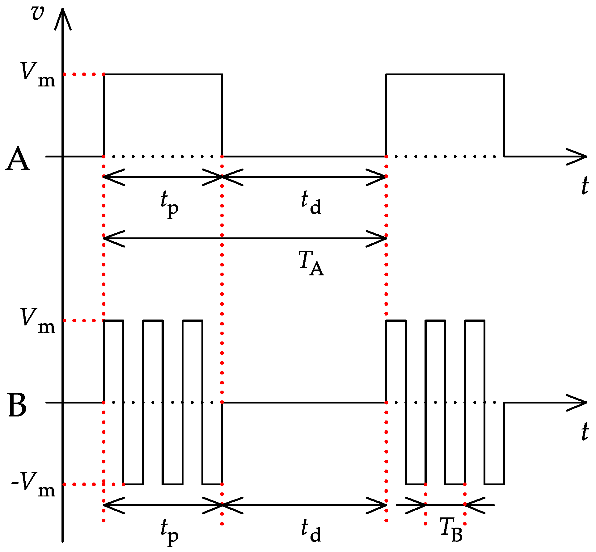
The process of IRE can be based on the use of unipolar or bipolar voltage pulses. DC IRE, where unipolar rectangular pulses (example A in Figure 1) are applied, is an older method. It requires a general anesthesia for a patient, who also needs muscle relaxants to prevent muscle contractions. There is a risk of arrhythmia during the process, so the pulses must be synchronized with ECG signals [10]. Electrolysis caused by DC current is other disadvantage of this method due to the formation of bubbles [11]. A typical pulse length is 100 s and the usual gap between pulses is 1 s. The output voltage normally reaches to units of kV [12].
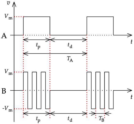
Figure 1.
Typical DC (A) and AC (B) electroporation pulses.
AC IRE, known also as H-FIRE, is a modern and more advantageous method compared to DC IRE. Unipolar pulses are replaced by the bursts of high-frequency bipolar pulses (example B in Figure 1). The typical length of one burst is similar to the duration of the unipolar pulse during DC IRE, and the gap between the bursts is also similar [13]. It is expected, that the patient will only need a local anesthesia. Cardiac function is usually unaffected [14] and no bubbles are formed, because electrolysis does not occur [15]. Problems with muscle contractions are minimized [16]. For these reasons, H-FIRE is very suitable for cardiac arrhythmia treatment and for cosmetic purposes. The amplitude of the pulses also reaches to kV units and the typical operating frequency is in the hundreds of kHz. Except symmetrical pulses with duty cycle 0.5, asymmetrical pulses [11] or pulses with lower duty cycle can be applied [17].
Rectangular pulses are used for the process of IRE in most cases, because it is simple to control the amount of energy delivered to the tissue and parameters of applied electric field are easily reproducible [18]. HV pulses are commonly generated by cheap and simple solid-state generators with MOSFET or IGBT transistors. The majority of these generators is based on the controlled discharge of HV capacitors into the load (tissue). As a part of our research, we have developed a compact AC generator for H-FIRE, where DC-AC inverter with pulse transformer is used and where the risk of uncontrolled discharge of the capacitor is eliminated.
2. Overview of Contemporary HV Generator Solutions
As already mentioned, almost all present solid-state generators, which are used for IRE, contain an HV capacitor bank. Voltage pulses are created by a transistor switch, which connects the capacitor directly to the load for a certain time. MOSFET transistors are usually used up to 1 kV voltage level, for higher values, IGBT transistors are suitable [19]. The capacitor bank is usually charged from the rectified AC mains by voltage regulator, which allows to set the output voltage. A DC-DC converter with pulse transformer can be used as the voltage regulator. Its transformer provides the galvanic isolation from the AC mains. The output voltage pulses are almost purely rectangular, because their rise and fall times are mainly affected by the switching time of the transistor [18]. This can be seen as the main advantage of this solution. On the other hand, there is a certain risk of uncontrolled discharge of the capacitor bank in the case, when the transistor switch is short-circuited. The device must be equipped with additional safety switch, that grounds the output terminals in the event of a fault [12]. It also leads to an increase in the demands on the control circuits, since the patient must not be endangered [20].
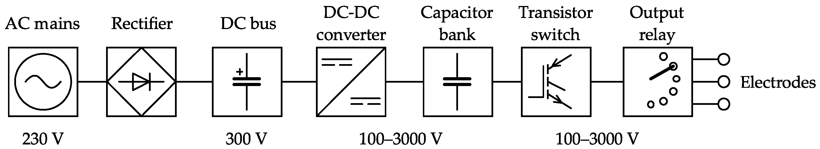
The first example of these generators is commercial NanoKnife device by AngioDynamics, which is proposed for DC IRE. Its block diagram can be seen in Figure 2. The device is powered from AC mains. Output voltage can be regulated from 100 to 3000 V and maximum output current value is 50 A. The length of pulses can be set from 20 to 100 s and the number of pulses from 10 to 100. The bank of HV capacitors is charged from low-power DC-DC converter with pulse transformer. Output voltage of this converter is proportional to the set duty cycle. Unipolar pulses are created by IGBT transistor switch. It is possible to connect 6 application electrodes, which are cyclically selected by relay switch. Electrodes can be used only once. The device is equipped with the additional safety IGBT transistor, which protects the patient from the risk of uncontrolled pulse in the case of the main IGBT transistor switch malfunction. The whole device is controlled by FPGA, which allows the synchronization with ECG. Output voltage and current are visualized on the screen [12,21].
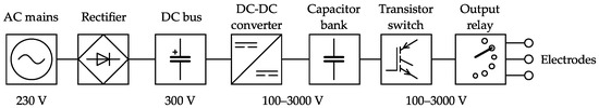
Figure 2.
Block diagram of the commercial device [12].
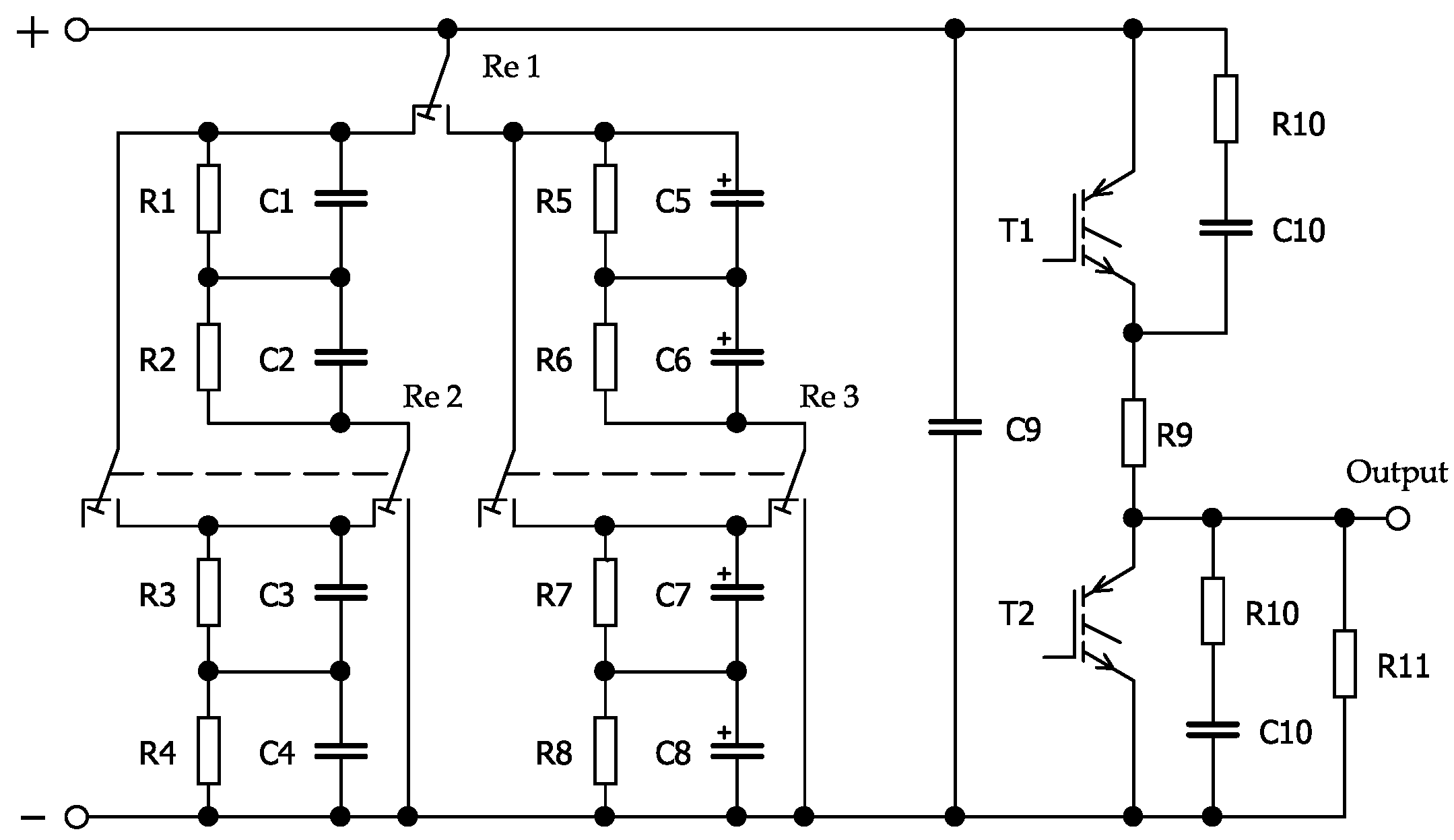
Similar compact DC generator called Electroporator was developed for experimental purposes by Stankevic et al. [22]. Amplitude of unipolar pulses can be regulated from 0 to 3.5 kV and their length from 3 s to 10 ms. Maximum output current reaches up to 250 A. Power part of the generator, which is shown in Figure 3, contains a variable capacitor bank, where partial capacitors are connected into serial or parallel combinations by HV relays. This solution allows to optimize the quantity of stored energy. Total capacitance of the bank is divided into 4 ranges from 13 to 1000 F, which are switched with dependence on selected pulse amplitude and duration. Pulses with higher amplitude are narrower, so the lower capacitance and higher working voltage of the bank is required. On the other hand, wider pulses with lower amplitude need an increase of the bank capacitance and decrease of its working voltage to reach a safe amount of stored energy. Capacitor bank is charged from regulated DC-DC source with maximum output voltage 4 kV. Pulses are formed by circuit with IGBT transistors, where transistor works as the main switch and transistor as the ‘crowbar’ switch. The ‘crowbar’ transistor cuts off a tail current of the main switch and makes the fall time of pulses sharp. The tail current is caused by switching-off time of the transistor . Both transistors are protected from voltage peaks by snubber circuits . To form a pulse, at first, the transistor is switched on and before the time, when is switched off, the ‘crowbar’ transistor is switched on. Resistor limits the transverse current, when both power transistors are switched on. The whole generator is controlled by ARM microcontroller. Desired pulse parameters are set via buttons and viewed on display. Effects of electroporation process are visualized on the second display in the pulse measuring unit [22].
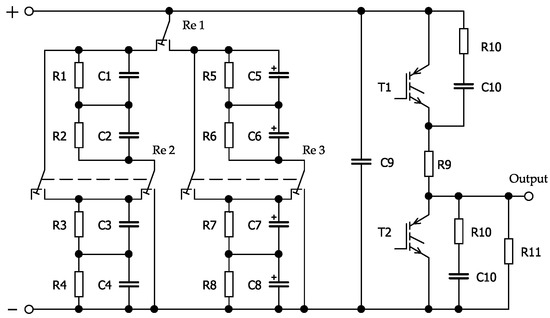
Figure 3.
Power part of the Electroporator device [22].
Both mentioned generators are designed for DC electroporation. The first HV generator for H-FIRE, whose block diagram can be seen in Figure 4, was patented in 2019. It is not a compact device, but group of connected laboratory instruments. Bursts of rectangular pulses are created by arbitrary function generator (Tektronix AFG 3011). The length of the burst, the gap between bursts and the number of bursts is controlled by microcontroller (Arduino Due). Pulse frequency can be varied from 250 kHz up to 2 MHz, the length of the burst is 100 s and the gap between bursts is 1 s. The capacitor battery is charged from an eight-channel programmable laboratory source (LabSmith HVS 448) with maximum output voltage ± 4000 V and maximum output current ± 2.5 mA. Electroporation pulses are created by two switching modules (IXYS HV 1000). Each module contains MOSFET transistors and control electronics. Maximum input voltage of the module is 950 V, maximum output voltage is ±850 V and maximum output current is 17 A. Control electronics is powered from AC mains. The first module is switched from the arbitrary function generator directly, control signal for the second one is inverted by an op amp signal inverter (LM 7171) [13].
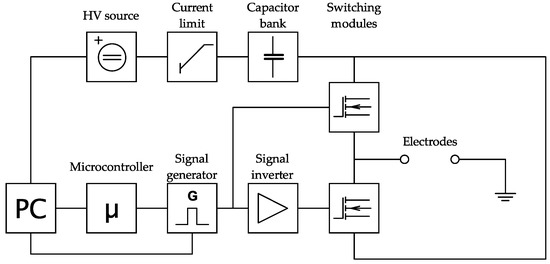
Figure 4.
Block diagram of experimental generator for H-FIRE [13].
Bursts of symmetrical pulses can be also produced by Marx generators. These simple circuits, which are mostly made of resistors, HV capacitors and spark gaps, generate exponential pulses [18]. Industrial generators are huge devices with peak power up to GW units [23]. However, when the spark gaps are replaced by power transistors, this generator with the appropriate control algorithm is able to produce rectangular pulses [24,25]. The use of transistors in Marx generators is limited by their maximum drain to source voltage, for this reason, solid-state-based generators can deliver lower output voltages up to kV units. A single Marx generator (Figure 5), which produces positive unipolar pulses, is suitable for DC IRE [24].
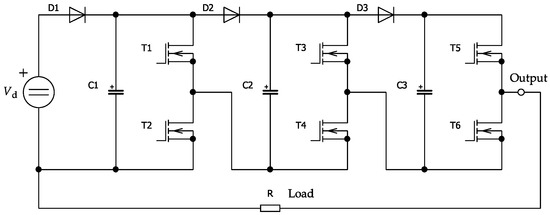
Figure 5.
Unipolar 3-stage solid-state-based Marx generator [24].
It is also possible to connect a pair of Marx generators to generate the bursts of bipolar pulses needed for the H-FIRE process. Both generators are powered from common DC supply and the load is placed between their outputs. Redondo et al. [24] designed an AC generator, which consists of two solid-state-based Marx generators assembled with five stages in each one. Both generators are powered from regulated DC-DC converter, whose maximum output voltage is 1 kV. Maximum output voltage of one generator is 5 kV and it can deliver 50 A to the load. The length of the pulse can be varied from 500 ns to 10 s and the number of pulses in each burst can be selected from 1 to 200.
A generator for DC IRE with pulse transformer was developed by Cervinka et al. [12]. This solution is different from devices mentioned above. A block diagram of this generator is shown in Figure 6. It is a cascade of two DC-DC converters. For both of them, a two-switch forward converter topology is used. Output voltage can be regulated from 0 to 5 kV, maximum output current is 100 A. An operator can also set the length of pulses from 20 to 150 s and the gap between pulses from 0.2 to 2 s. The first converter is used for DC voltage regulation in the second DC bus constructed from HV film capacitors with total capacitance of 100 F. The amplitude of unipolar pulses is proportional to this voltage, which can be regulated from 0 to 1200 V. Unipolar pulses are generated by the second DC-DC converter, whose power part contains IGBT transistors with maximum drain to source voltage 1700 V and maximum drain current 1000 A. These transistors are controlled by the integrated drivers. Secondary rectifier is constructed from 10 series-connected SiC diodes. Reverse voltage of each diode is 1200 V and average forward current is 68 A. The total reverse voltage is 12 kV. As the load has a resistive character, secondary free-wheeling diode is omitted. Application electrodes are switched by the output relay switch. An overcurrent protection measures the primary current of the second transformer and interrupts the control signals, when the overcurrent occurs. Primary and secondary current and voltage in the second DC-bus are sensed by LEM sensors. The whole device is controlled by signal processor and user interface is based on an alphanumeric display, where selected parameters of the output voltage are viewed [12].
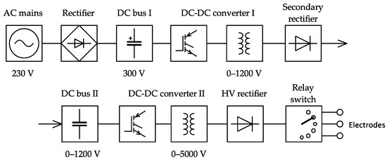
Figure 6.
Block diagram of DC IRE generator with pulse transformer [12].
In contrast to generators with HV capacitors, this solution suppresses the risk of the uncontrolled discharge of the capacitor, because the capacitor bank is placed in the DC bus. When the fault in control circuits occurs, the core of the transformer is saturated and magnetizing current rises. The independent overcurrent protection responds to this increase and the control signals for power part are interrupted. Power transistors at switch-off state are also stressed by lower voltage [12].
3. Design of the High-Voltage AC Generator with Pulse Transformer
As the part of our research focused on electroporation, a new AC generator for H-FIRE was developed in cooperation with the International Clinic Research Center of St. Anne’s Hospital Brno (FNUSA-ICRC). We have decided to use the DC-AC inverter with pulse transformer, because this solution is not commonly used at these applications and because the source with pulse transformer has proven itself in older HV generator for DC IRE (Figure 6). A power part of the generator is very simple and it does not require any complex control algorithm (compared to the pair of Marx generators with many transistors). The risk of uncontrolled discharge of the capacitor bank is eliminated here, because the capacitors placed in the DC bus are short-circuited in the event of the power transistor malfunction.
3.1. Properties of the Generator
Our goal was to develop a new AC generator similar to the patented HV supply [13]. The generator is proposed especially to catheter ablation of cardiac arrhythmia, for this reason, lower values of output voltage of about 1–2 kV are required [26]. We decided to design two pulse transformers with different winding ratios to find out whether a higher voltage and lower current or a lower voltage and higher current is more suitable to achieve a higher effect of electroporation. A peak output power is the same for both cases and is limited by the supply voltage and by the maximum drain current of used transistors. The main parameters of the generator are summarized in Table 1.

Table 1.
Main parameters of the generator.
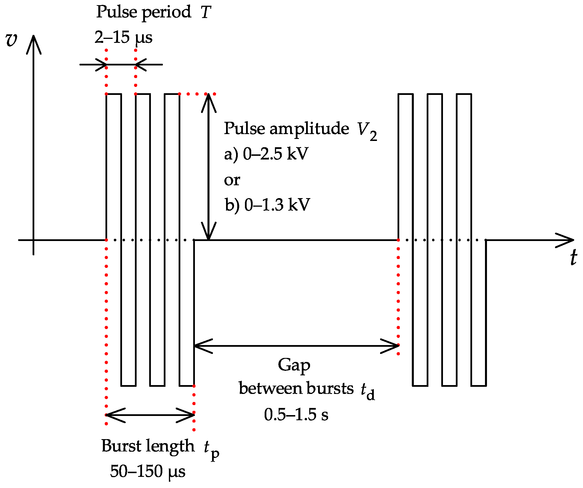
Output bursts of symmetrical bipolar pulses with labels are shown in Figure 7. The user can set the output voltage, the frequency of pulses, the length of the burst and the length of the gap between bursts. All required values can be set via buttons located on the front panel, where there are also LED displays and terminals. The output voltage and the number of bursts are visualized on theses displays. The value of the output current is viewed on the LED bar graph. It is possible to connect an oscilloscope to show the output current and external ECG signal to synchronize the bursts. The oscilloscope can be triggered from synchronization output.
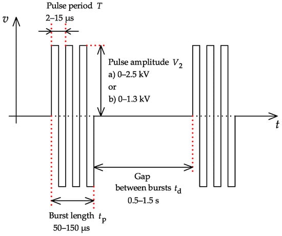
Figure 7.
Output voltage of the generator.
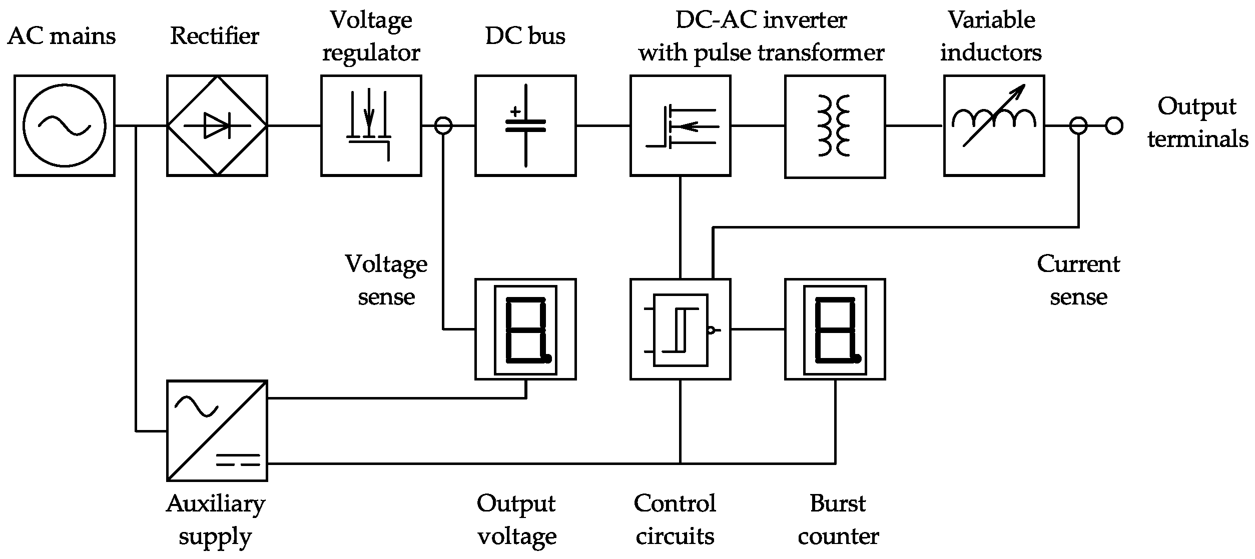
The generator consists of four main parts: power part, control circuits, displays, and auxiliary supply. The power part contains a DC-AC inverter, linear voltage regulator, and variable output inductors. Gate signals for power transistors are generated by the integrated gate driver and these transistors are protected by the overcurrent protection, which responds to the primary current increase. The block diagram of the generator is shown in Figure 8.
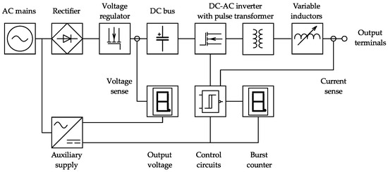
Figure 8.
Block diagram of the generator.
3.2. Power Part of DC-AC Inverter
Power part of the generator is shown in Figure 9. Full bridge consists of transistors , where transistors and or and are switched together. Both diagonals work with permanent duty cycle = 0.5. Switch-on state must be shortened by dead time to avoid a short circuit in a leg (1 or 2). Magnetizing current of the transformer is an integral of primary voltage . Primary voltage has a rectangular shape, so the shape of magnetizing current is triangular. Primary current is a sum of secondary current transformed to primary side and magnetizing current . Secondary voltage is also rectangular, the height of pulses is different with winding ratio /. Capacitor is used for elimination of DC magnetization of the core. This problem occurs, when control signals are affected by interference and one diagonal works with slightly different duty cycle than the second one. As the result, primary voltage contains a DC component, which causes DC magnetization. In the case of duty cycle deviation, capacitor is charged to this DC voltage and saturation of the core is suppressed [27,28]. Used power transistors are IXFK100N65X2 by IXIS with following features: maximum drain to source voltage = 650 V, maximum drain current = 100 A , drain to source resistance = 30 m, package TO-264. At this application, transistors are used up to their nominal current without thermal overload, because the length of the burst is very short in contrast to the length of the gap between them.
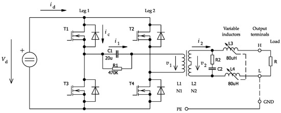
Figure 9.
Circuit diagram of the power part.
3.3. Pulse Transformer Design
For both transformers LjU 7020 core (U-shape) with effective area = 400 , effective length = 269.8 mm, and relative permeability = 2100 was chosen. Number of primary turns is calculated (1) for minimum frequency = 65 kHz and maximum voltage in DC-bus = 320 V, when chosen maximum flux density value = 0.35 T is reached [27,29].
The primary winding has nine turns. Transformers are not designed with respect to optimal core size, because minimum leakage inductance and safe isolation is more important at this application. For this reason, U-core is used. Number of secondary turns is calculated from winding ratio (2), where = 2.5 kV (or = 1.3 kV) is the amplitude of secondary pulses and = 300V is the voltage in DC-bus. This value is chosen with respect to estimated voltage drops on components at the power part [27,29].
Transformer with higher output voltage has = 76 secondary turns and the other one has = 40 secondary turns. Maximum value of the magnetizing current (3) is also calculated for voltage = 320 V and minimum frequency = 65 kHz [27,28].
For these values, = 4 A is obtained. Although it is not obvious from (3) at the first sight, magnetizing current decreases for higher frequencies. Flux density , which is squared at the numerator of fraction (3), decreases when the working frequency rises (1) and thus, it leads to drop of the magnetizing current [27,29]. Peak value of the secondary current is limited by the maximum drain current of used transistors. The overcurrent protection is set to respond to the increase of primary current above 96 A (maximum drain current of used transistors is 100 A). Peak value of the secondary current is given by (4), where = 96 A is the nominal primary current.
The transformer with higher secondary voltage ( = 76 turns) can deliver peak current = 11 A and the transformer with lower secondary voltage ( = 40 turns) delivers peak current = 21 A. Delivered peak current slightly rises for higher frequencies, because the magnetizing current decreases (3). Cross section area of a primary and secondary conductor is dimensioned to RMS value of the current as a general rule because of power dissipation. RMS value of rectangular pulses with duty cycle = 0.5 is equal to their peak value, so the conductors should be dimensioned to values , , but it would be uneconomical. At this application, it is necessary to calculate the RMS values with respect to burst length and gap between bursts (5). Magnetizing current is neglected to simplify the calculation [28,29].
The most unfavorable case become, when the user sets the longest burst = 150s and the shortest gap = 0.5s and primary current reach its nominal value. For both transformers, RMS value of the primary current = 1.66 A is calculated. Secondary current of the transformer 1 has RMS value = 0.19 A and for the transformer 2, = 0.36 A is obtained. The cross section area depends on opted current density (6) [27].
For opted current density , cross section area = 1.66 of the primary winding is calculated. Since the winding consists of two parallel branches, cross section area of the conductor is 0.83 . Secondary conductor of the transformer 1 has cross section area = 0.19 and secondary conductor of the transformer 2 has = 0.36 . Conductors must be divided into M thin insulated conductors because of skin effect suppression [27]. A skin depth (7) decreases, when the working frequency rises, so it is needed to calculate with upper border of the range = 470 kHz [27,30]. A copper has specific resistance and relative permeability = 0.999.
For frequency = 470kHz, skin depth = 0.096mm is obtained. The diameter of thin partial conductor must be lower than or equal to double of the skin depth (8) [27].
Primary winding should have = 29 partial conductors, secondary winding of the transformer 1 should contain = 7 conductors and secondary winding of the transformer 2 should consist of = 13 conductors (9).
Single-layer windings are created from high-frequency litz wire V155 type. Primary wire consists of 81 partial conductors with = 0.12 mm and total cross section area = 0.92 . This winding consists of four parallel branches, when two branches are situated to one leg of the U-core. Thus, total cross section area of the primary winding is 4 = 3.68 . For both transformers, secondary wire consists of 50 partial conductors with = 0.1 mm and total cross section area = 0.39 . Secondary winding of the transformer 1 ( = 76 turns) consists only of one branch, when each half of the winding is situated to one leg of the core. Secondary winding of the transformer 2 ( = 40 turns) consists of two parallel branches, so the total cross section area is 2 = 0.78 . Each branch is situated to one leg of the core. A window area of used core offers a plenty of space, so all cross section areas are higher than calculated values. That is advantageous, because it leads to decrease of the voltage drop on the transformer.
3.4. Output Inductor Design
During our experiments, we have found that the tissue is not a purely resistive load, but its character is slightly resistive-capacitive. The charging of the capacitive component of the load causes a current peaks, which lead to the overcurrent protection response. For this reason, output voltage had to be decreased, but this step led to a drop of the electroporation effect. We decided to suppress these current peaks by a pair of appropriate inductors connected between secondary winding of the transformer and the output terminals. Inductors are paired, because we wanted to keep the output symmetrical.
If we neglect the capacitive component, inductors and the tissue create a serial inductive-resistive load characterized by time constant = /. We found, that the load impedance (e.g., tissue, wiring, etc.) is about 100–200 at mostly applied frequency = 100 kHz. The time constant = 1 s was chosen as the tenth of the pulse period = 1/ = 10 s. If we consider resistance = 100 and time constant = 1 s, then inductance = 100 H is obtained. We have decreased this value to = 80 H for each inductor, so the rise time of the output voltage is not too limited at 100 kHz. Inductors are single-layer air coils due to low parasitic parallel capacitance. They are created on plastic pipes with diameter = 28 mm, diameter of used wire is = 0.8mm. Number of turns = 83 was calculated from (10) [29].
As the inductors are paired, the total inductance is twice the chosen value. The impedance of the load depends on many factors (e.g., specific tissue, electrode surface, pressing force between electrode and tissue, etc.). For this reason, inductors are variable. Their inductance can be decreased on a half or on a quarter of the total value, or they can be totally short-circuited. This is provided via mechanical selector on the front panel. Branches connected to selector are routed out after 21 turns and 42 turns from the beginning of the winding. The appropriate value of the inductance is switched at the beginning of the electroporation process by the user, whose decision depends on the output current waveform, which is measured by the oscilloscope.
3.5. DC Bus Voltage Regulator
DC bus is created from two electrolytic capacitors (1000 F each) and two film capacitors (1 F each) shown in Figure 10. AC mains voltage is rectified by a bridge rectifier –. Capacitors in DC-bus are charged through transistor and resistor and discharged by transistor and resistor with dependence on position of the potentiometer . The potentiometer must be in plastic case, because this circuit is connected with the mains. Passive input EMI filter consists of common-mode chokes , and film capacitors –. To protect, a fuse is used. Described regulator is used due to its simplicity, transistors working in a linear mode are not a source of noise and dissipated power is negligible, because current flowing through transistors is relatively low [27].
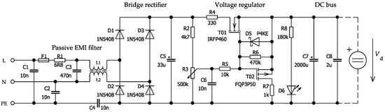
Figure 10.
Circuit diagram of the linear voltage regulator.
3.6. Control Circuits
The control unit, which is based mainly on Schmitt triggers and other logic gates, is simple and allows to set the time parameters of electroporation pulses. It generates the gate signals for power transistors and protects them from the overcurrent. The unit consists of some blocks shown in Figure 11. Pulses (Q and ) are generated by oscillator (CMOS 4047), which produces also clock signal (CLK) for D-type flip-flop (CMOS 4013). Frequency is changed by potentiometer. Signals (Q and ) are routed to inputs (IN A and IN B) of the integrated driver (UCC 27524), whose outputs are boosted by N and P MOSFET transistors. Galvanic isolation of gate signals for power transistors is provided by a small transformer. Pulse generator works permanently, so bursts are created by enabling the integrated driver for a certain time.
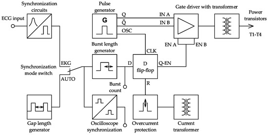
Figure 11.
Block diagram of the control circuits.
A generator of the burst length is triggered at a rise time of the signal, which is routed to its input from a synchronization mode switch. A source of this signal can be a gap length generator (AUTO mode) or a synchronization circuit (ECG mode). The length of the burst is set by potentiometer and this block also contains a safety flip-flop circuit triggered on a fall time of the input signal from the mode switch. This additional safety circuit does not allow a formation of the next burst less than 0.3 s after the end of the previous one. It is important particularly in ECG mode, when the input signal can be affected by noise. Output signal from the burst length generator is routed to D-input of the flip-flop 4013. Its S-input is grounded and when a rise time comes to its D-input, signal from the Q-EN-output enables the integrated driver and power part is activated.
Gap length generator works as a relaxation oscillator. Its period can be selected from 0.5 to 1.5 s. The output signal is routed to mentioned mode switch. Synchronization with ECG is based on the use of an optocoupler, which works as a signal-shaping circuit and provides also a galvanic isolation of the input signal. Pulses from the synchronization mode switch are also routed to additional flip-flop circuit to trigger the oscilloscope. The output terminal for the oscilloscope is isolated by the second optocoupler, which also works as the signal inverter. Primary current of the power transformer is sensed by current transformer, rectified and routed to a shunt resistor. When the primary current exceeds its nominal value = 96 A, the D flip-flop 4013 is reset by its R-input and the power part is disabled. This block contains also an undervoltage protection. Supply voltage + 15 V is checked by comparator based on TL 431 regulator, and when the supply voltage decreases below 13 V, the power part is also disabled.
3.7. Displays and Auxiliary Supply
Display unit consists of V-meter, burst counter and output current indicator. V-meter measures the voltage in DC-bus. Its sensing divider is calculated to view the amplitude of the output voltage in units of kV. Since power transformers are replaceable, the divider must be adjustable to measure two different maximum values. V-meter is based on common A/D converter ICL 7107 with LED display. Input signal for the three-digit burst counter is taken from the D-input of the flip-flop 4013 (Figure 11). The circuit is based on CMOS 4026 counters with integrated LED drivers. Output current is indicated by LED bar graph controlled by LM 3914 linear mode LED driver. The current is sensed by appropriate current transformer with rectifier and adjustable shunt resistor. Then is magnified by a transistor amplifier. The control circuits and the burst counter are supplied from +15 V DC supply, while the V-meter requires symmetric ±5 V DC supply. Both supplies, whose grounds are isolated, consist of mains transformer, bridge rectifier and linear voltage regulators. Output current indicator is also powered from +5 V leg of the symmetric supply.
4. Results and Discussion
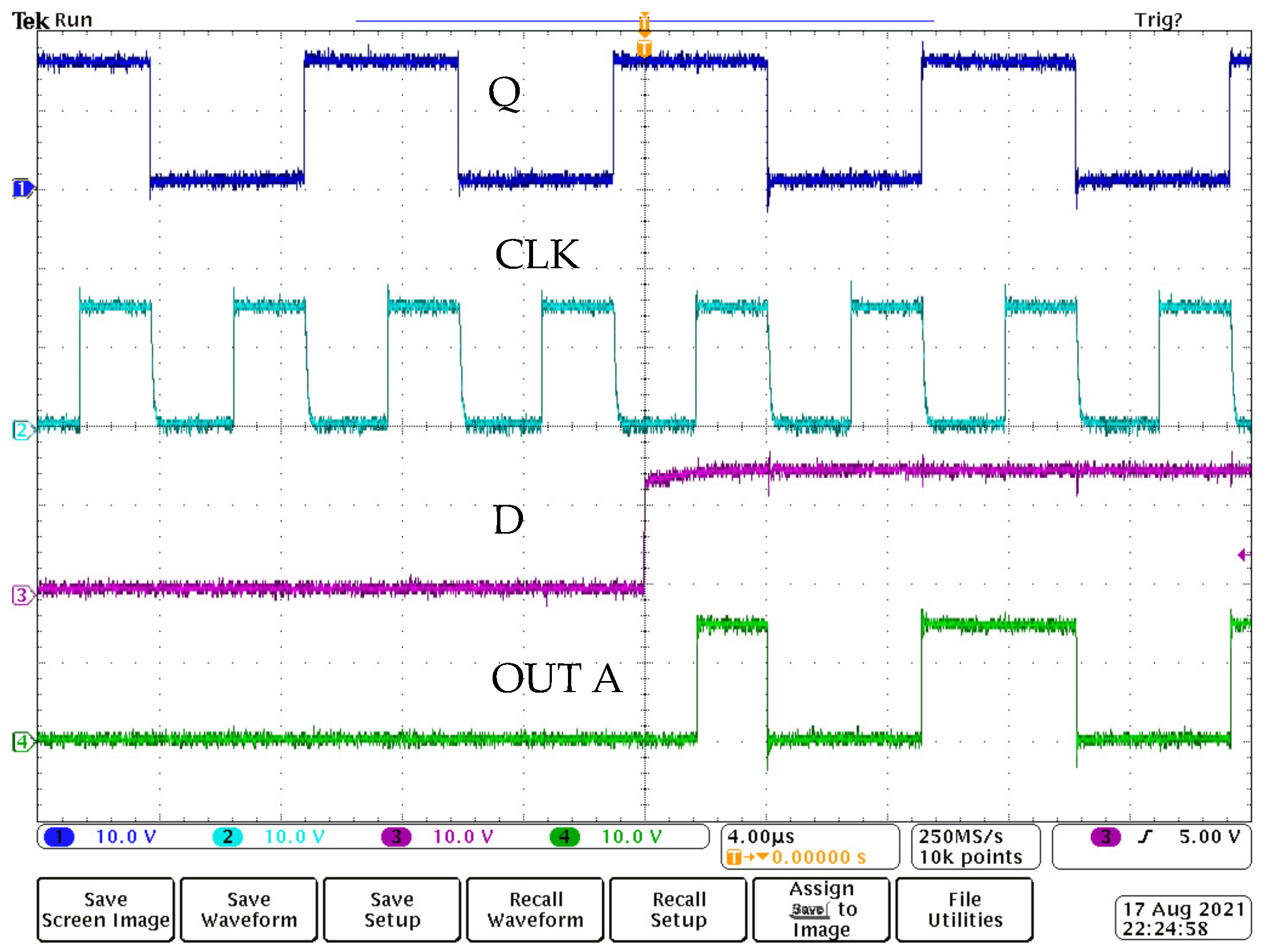
At first, control circuits were tested. Important control signals are viewed in Figure 12. As mentioned above, pulse generator (4047) runs permanently. Its output signals Q and CLK are shown on the top. The rise time of the signal D enables the integrated driver (UCC27524) and power part is activated. One of the gate signals from the integrated driver (OUT A) is shown below. The time shift between the rise time of the D signal and OUT A signal is caused by signal transcription at the flip-flop (4013), which is triggered by rise time of the clock signal (CLK). As the clock signal frequency is twice the output signal (Q), the first and the last pulse of the burst has a half length. This unusual solution leads to a gradual increase and decrease of the magnetizing current.
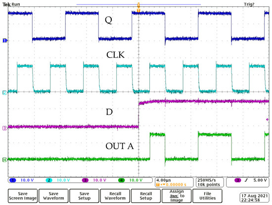
Figure 12.
Control signals, 10 V/div and 4 s/div.
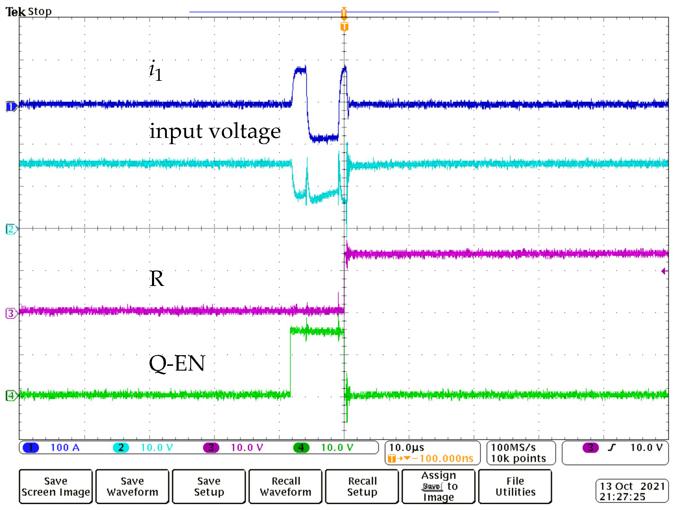
A response of the overcurrent protection is shown in Figure 13. The primary current is sensed by current transformer. Its secondary current is rectified and routed to the shunt resistor. An input voltage of the protective circuit is created as a difference between constant DC supply voltage +15 V and a voltage drop on mentioned shunt resistor. It means that the input voltage has a constant value, when the primary current is zero and decreases, when the primary current rises. The overcurrent protection responds, when the primary current exceeds its nominal value (96 A). In this case, the input voltage decreases below 7 V, and as the result, flip-flop 4013 is reset by its R-input. Enable signal (Q-EN) drops to zero and the integrated gate driver UCC 27524 is permanently disabled. To reset the protection, the AC mains switch must be turned off and on.
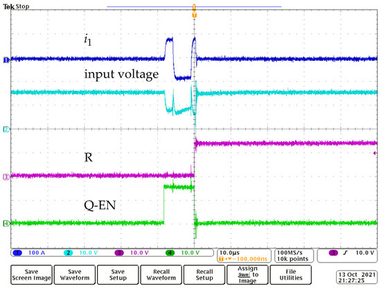
Figure 13.
Response of the overcurrent protection, 100 A/div, 10 V/div, and 10 s/div.
The power part of the generator was firstly tested with the transformer with lower secondary voltage. The waveform shown in Figure 14 is the result of the Simulink Simscape model. The length of the burst is 100 s and the pulse frequency is 100 kHz. Output inductors are short-circuited and maximum output voltage = 1.3 kV is set. Load resistance = 100 is connected. It can be seen, that voltage pulses are almost purely rectangular. Real output voltage measured on resistive load = 100 is viewed in Figure 15. Pulse frequency = 100 kHz is the same as in the model and output inductors are short-circuited. It is obvious, that the voltage exceeds 1.5 kV value, so the generator has a certain voltage reserve. In contrast to simulation, rise and fall times are influenced by the leakage inductance of the transformer, but not significantly. Differences between simulated and measured voltages are also caused by parasitic properties (parasitic inductance of the load resistor and wiring, parasitic resistance and capacitance of the transformer, etc.), which were not considered in the simulation.
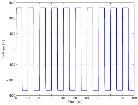
Figure 14.
Simulated output voltage, V = 1.3 kV, R = 100 , f = 100 kHz.
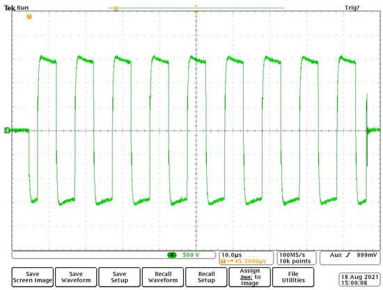
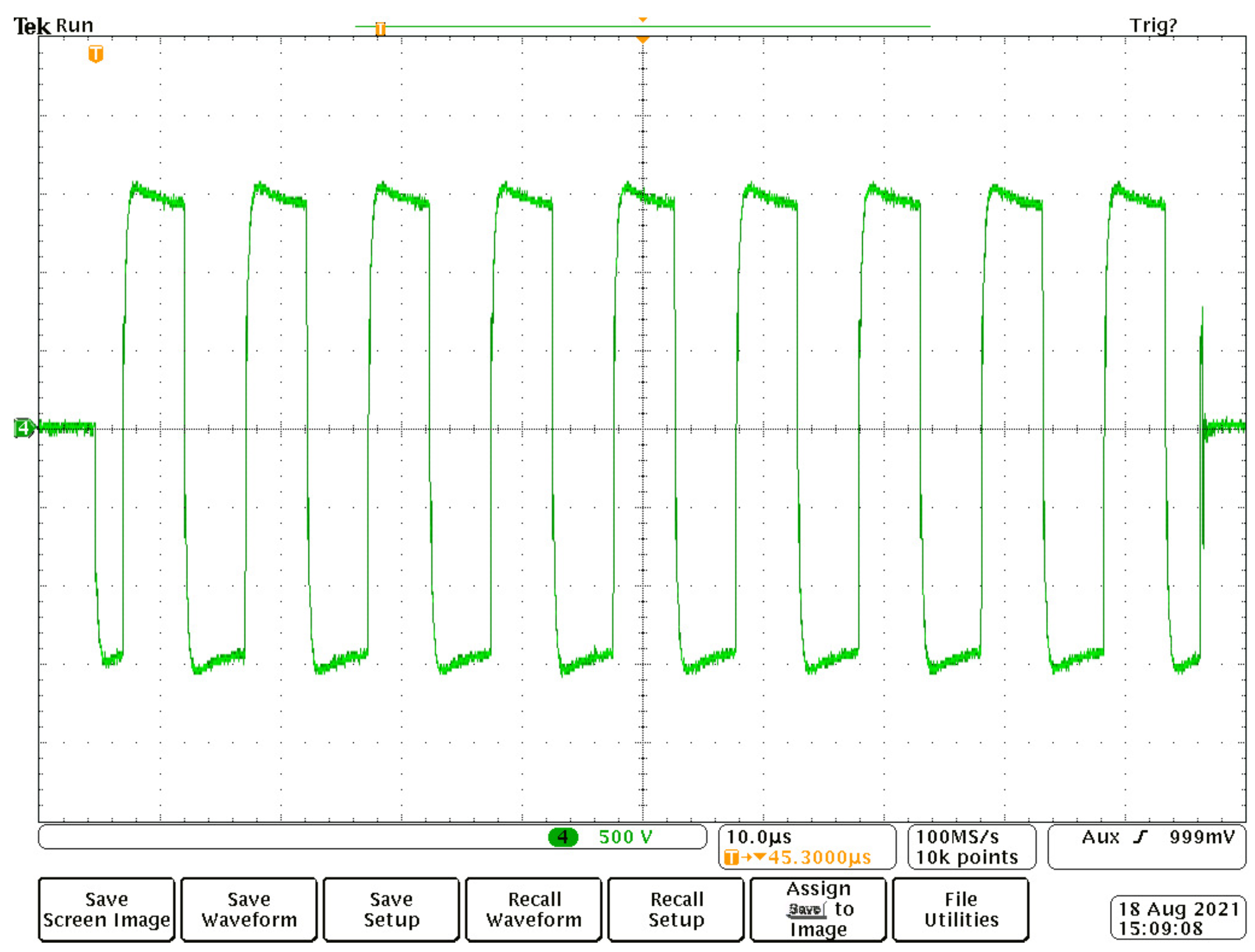
Figure 15.
Real output voltage, R = 100 , 500 V/div, and 10 s/div.
Finally, the output voltage and current measured on cardiac tissue during the H-FIRE process are shown in Figure 16. Voltage peaks rise up to 1 kV and maximum current is 10 A. Pulse frequency = 100 kHz was set and output inductors were short-circuited. Waveforms are different from the voltage obtained by the simulation (Figure 14) and from the voltage measured on resistive load (Figure 15). Differences are caused by the transformer leakage inductance and capacitive component of the load, etc. We are not able to compare the voltage measured on tissue impedance load with appropriate simulation, because the tissue represents a very nonlinear environment and its model is the subject of our further research.
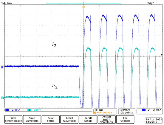
Figure 16.
Output voltage and current, cardiac tissue, 200 V/div, 2 A/div, and 10 s/div.
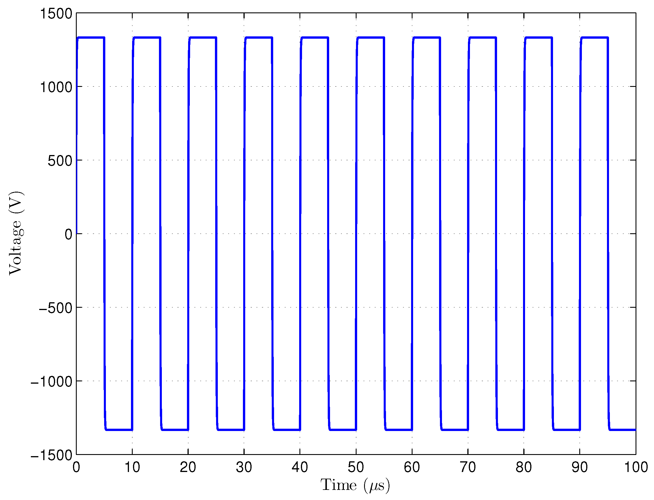
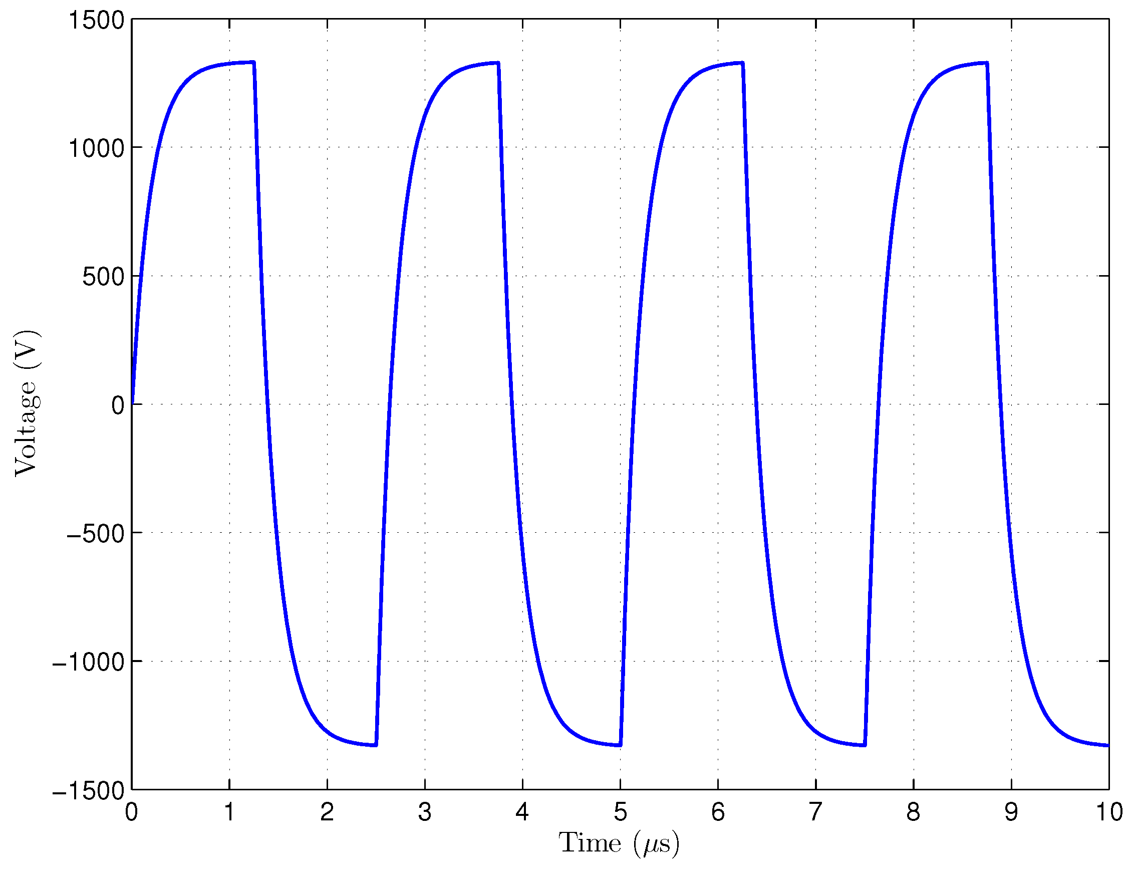
We also simulated the output voltage on resistive load = 100 at a frequency of 400 kHz. This frequency was not applied to the cardiac tissue, because higher frequencies will be used in further experiments. Except pulse frequency, other parameters of the simulation were the same as in previous case (Figure 14) and parasitic properties of all components were not considered except the leakage inductance. Result of this simulation can be seen in Figure 17. Rise and fall times are significantly longer than at frequency of 100 kHz due to mentioned transformer leakage inductance, so the shape of pulses is different from the ideal rectangular waveform.
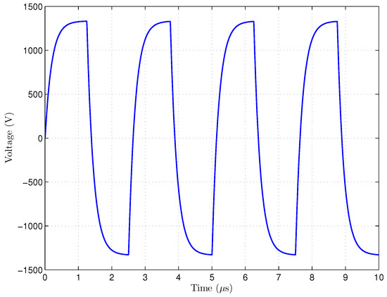
Figure 17.
Simulated output voltage, V = 1.3 kV, R = 100 , f = 400 kHz.
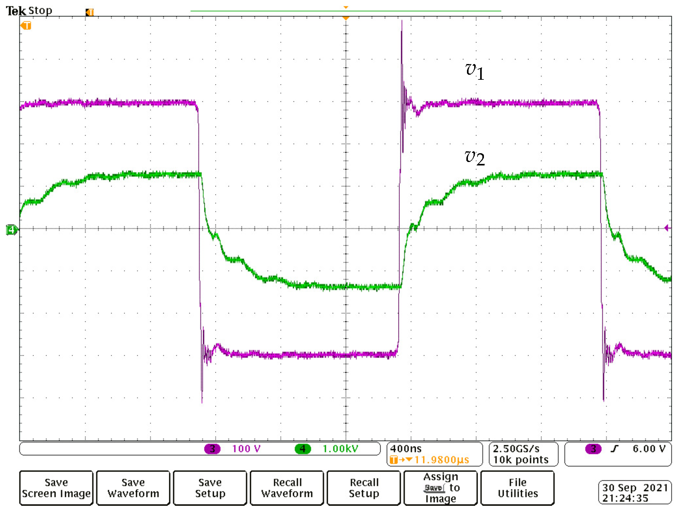
To compare with simulation result shown in Figure 17, the output voltage measured on resistive load = 100 is viewed in Figure 18 together with primary voltage . The output inductors were short-circuited as in all previous cases. The shape of secondary voltage is similar to waveform obtained by the second simulation and the effect of leakage inductance is visible on the difference between rise and fall, resp., times of both waveforms. Peaks of the primary voltage are caused by the parasitic inductance in the leg of the inverter.
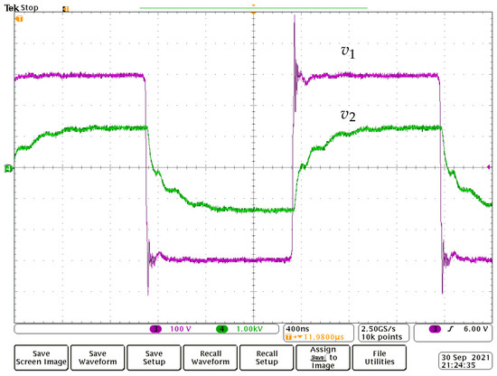
Figure 18.
Primary and secondary voltage, 100 V/div, 1 kV/div, and 400 ns/div.
We can say, that the parasitic properties (leakage inductance, parasitic resistance and capacitance, etc.) are the main limit of using the transformer in this application. The effect of leakage inductance, which causes significant differences between ideal and real waveforms, increases with working frequency and load current. Waveforms measured on the resistive load are different from results obtained by the simulation, because the real leakage inductance is higher, and, as already mentioned, parasitic properties of other components were not considered in the simulation.
Internal layout of the generator is shown in Figure 19. The device is built in a compact case. Main boards are mounted to the bottom of the case except the display board, which is placed behind the front panel. Output inductors with their selector switch create a compact unit. Pulse transformer is inserted into grooves in two plastic blocks and tightened by screws. Boards are connected by a cable form with connectors.
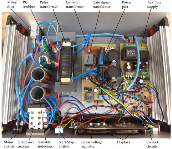
Figure 19.
Internal layout of AC generator.
During H-FIRE experiments, we tried to compare the electroporation effect for both power transformers. We set the length of the burst of 100 s, and 1 s gap between bursts. Pulse frequency 100 kHz was set and we tried to apply the output voltage as high as possible. The transformer with higher output voltage = 2.5 kV was used only once and the electroporation effect was completely insignificant, because no lesions were found. The load impedance was relatively low, so the generator was not able to deliver more than 10 A into it. On the other hand, when we used the transformer with lower output voltage = 1.3 kV, we were able to deliver maximum output voltage, the current exceeded 15 A in some cases, and then visible lesions were found. Although the evaluation of lesion depth is still ongoing, we can say, that the transformer with lower winding ratio is more suitable, because higher current and also higher amount of energy can be delivered to the tissue at the voltage level about 1 kV.
5. Conclusions
This paper refers about the design of a high-voltage AC generator, which is proposed for high-frequency irreversible electroporation (H-FIRE). This method is more advantageous than older DC irreversible electroporation, because the cardiac function is mostly unaffected, muscle contractions are insignificant, and unwanted electrolysis does not occur.
Most HV generators designed for electroporation are based on controlled discharge of the capacitors into the load (tissue). Main advantage of this solution are purely rectangular voltage pulses. However, there is a certain risk of uncontrolled discharge of the capacitor in the case of transistor switch malfunction. Commercial generators must contain additional safety switch for this reason.
We present different solution of AC generator, where a DC-AC inverter with pulse transformer is used. We decided to use this topology, because it is not commonly used and we tried to verify its suitability for this application. Our generator is able to deliver bursts of symmetrical rectangular pulses. Burst length can be varied from 50 to 150 s and the gap between bursts from 0.5 to 1.5 s. Wide frequency range from 65 to 470 kHz is suitable for experimental use. Two power transformers with different winding ratios were designed, so two different maximum values of the output voltage are achieved. Additional variable inductors can suppress capacitive component of output current, if it is necessary.
The AC generator was successfully used for experiments with cardiac tissue of pigs. Problems with cardiac function did not occur and muscle contractions were insignificant. We found, that the transformer with lower winding ratio is more advantageous, because the amount of energy delivered to the tissue is higher at the same voltage level about 1 kV, so visible lesions are created.
Author Contributions
Conceptualization, D.C. and M.F.; validation, M.F. and D.C.; investigation, M.F., D.C. and P.P.; writing—original draft preparation, M.F.; writing—review and editing, D.C.; project administration, P.P. All authors have read and agreed to the published version of the manuscript.
Funding
This research work has been carried out in the Centre for Research and Utilization of Renewable Energy (CVVOZE). Authors gratefully acknowledge financial support from the Ministry of Education, Youth and Sports under institutional support and BUT specific research programme (project No. FEKT-S-20-6379).
Conflicts of Interest
The authors declare no conflict of interest.
References
- Jourbachi, N.; Beroukhim, K.; Tafti, B.; Kee, S.; Lee, E. Irreversible Electroporation in Cancer Treatment. Gastrointest. Interv. 2014, 1, 8–18. [Google Scholar] [CrossRef] [Green Version]
- Kotnik, T.; Frey, W.; Sack, M.; Meglic, S.H.; Peterka, M.; Miklavcic, D. Electroporation-based Applications in Biotechnology. Trends Biotechnol. 2015, 33, 480–488. [Google Scholar] [CrossRef]
- Pudasaini, S.; Perera, A.T.K.; Ahmed, S.S.U.; Chong, Y.B.; Ng, S.H.; Yang, C. An Electroporation Device with Microbead-Enhanced Electric Field for Bacterial Inactivation. Inventions 2020, 5, 2. [Google Scholar] [CrossRef] [Green Version]
- Golberg, A.; Fischer, J.; Rubinsky, B. The use of irreversible electroporation in food preservation. In Irreversible Electroporation; Rubinsky, B., Ed.; Series in Biomedical Engineering; Springer: Berlin, Germany, 2010; pp. 273–312. [Google Scholar]
- Davalos, R.; Rubinski, B. Temperature considerations during irreversible electro-poration. Int. J. Heat Mass Transf. 2008, 1, 5617–5622. [Google Scholar] [CrossRef]
- Rebersek, M.; Miklavcic, D. Advantages and Disadvantages of Different Concepts of Electroporation Pulse Generation. Automatika 2011, 52, 12–19. [Google Scholar] [CrossRef] [Green Version]
- Cervia, L.D.; Chang, C.C.; Wang, L.; Mao, M.; Yuan, F. Enhancing Electrotransfection Efficiency through Improvement in Nuclear Entry of Plasmid DNA. Mol. Ther. Nucleic Acids 2018, 11, 263–271. [Google Scholar] [CrossRef] [PubMed] [Green Version]
- Broderick, K.; McCoy, J.; Kemmerrer, S.V. Minimally Invasive Dermal Electroporation Device. US20200246613A1, 24 April 2020. [Google Scholar]
- Rubinsky, B. Irreversible Electroporation, 1st ed.; Springer: Berlin, Germany, 2010. [Google Scholar]
- Li, J.; Zhang, X.B.; Wang, J.J.; Jin, L.J.; Shan, H.S.; Zhang, X.; Ma, L.; Xue, X.D.; Zhang, X.; Zhang, Z.L.; et al. Comparison between high-frequency irreversible electroporation and irreversible electroporation ablation of small swine liver: Follow-up of DCE-MRI and pathological observations. Chin. Med. J. 2021, 34, 2081–2090. [Google Scholar] [CrossRef] [PubMed]
- van Es, R.; Konings, M.K.; Pré, B.C.D.; Neven, K.; van Wessel, H.; van Driel, V.J.H.M.; Westra, A.H.; Doevendans, P.A.F.; Wittkampf, F.H.M. High-frequency irreversible electroporation for cardiac ablation using an asymmetrical waveform. BioMed. Eng. Online 2019, 18, 1475–1488. [Google Scholar] [CrossRef] [PubMed] [Green Version]
- Cervinka, D.; Novotna, V. High-Voltage Pulse Source for Cell Electroporation. In Advances in Intelligent Systems and Computing, Proceedings of the 12th International Conference on Mechatronics, Brno, Czech Republic, 6–8 September 2017; Springer: Cham, Switzerland, 2018; pp. 1–6. [Google Scholar] [CrossRef]
- Arena, C.B.; Davalos, R.V.; Sano, M.B. High Frequency Electroporation for Cancer Treatment. U.S. Patent US20120109122A1, 22 October 2019. [Google Scholar]
- Arena, C.B.; Sano, M.B.; Rossmeisl, J.H. High-frequency Irreversible Electroporation (H-Fire) for Non-thermal Ablation Without Muscle Contraction. BioMed. Eng. Online 2011, 10, 102. [Google Scholar] [CrossRef] [PubMed] [Green Version]
- Pesl, M.; Vitecek, J.; Cernik, M.; Novotna, V.; Cervinka, D.; Caluori, G.; Kulik, T.; Kubala, L.; Starek, Z. Microbubbles as Safety Issue of Novel Catheterization Ablation Methods. In Proceedings of the 8th European Medical and Biological Engineering Conference (EMBEC 2020), Portorož, Slovenia, 29 November–3 December 2020; Jarm, T., Mahnic-Kalamiza, S., Cvetkoska, A., Miklavcic, D., Eds.; Fakuleta za Elektrotehniko, Ljubljana: Ljubljana, Slovenia, 2020; p. 245. [Google Scholar]
- Yao, C.; Dong, S.; Zhao, Y.; Liu, Y.L.H.; Gong, L.; Ma, J.; Wang, H.; Sun, Y. Bipolar Microsecond Pulses and Insulated Needle Electrodes for Reducing Muscle Contractions During Irreversible Electroporation. IEEE Trans. Biomed. Eng. 2017, 64, 2924–2937. [Google Scholar] [CrossRef] [PubMed]
- Ringel-Scaia, V.M.; Beitel-White, N.; Lorenzo, M.F.; Brock, R.M.; Huie, K.E.; Coutermarsh-Ott, S.; Eden, K.; McDaniel, D.K.; Verbridge, S.S.; Rossmeisl, J.H.; et al. High-frequency irreversible electroporation is an effective tumor ablation strategy that induces immunologic cell death and promotes systemic anti-tumor immunity. EBioMedicine 2019, 44, 112–125. [Google Scholar] [CrossRef] [PubMed] [Green Version]
- Rebersek, M.; Miklavcic, D.; Bertacchini, C.; Sack, M. Cell Membrane Electroporation—Part3: The Equipment. IEEE Electr. Insul. Mag. 2014, 30, 8–18. [Google Scholar] [CrossRef]
- Kasri, N.F.; Piah, M.A.M.; Adzis, Z. Compact High-Volatge Pulse Generator for Pulsed Electric Field Applications: Lab Scale Development. J. Electr. Comput. Eng. 2020, 2020, 6525483. [Google Scholar] [CrossRef]
- Medical Electrical Equipment—Part 1: General Requirements for Safety and Essential Performance, IEC 60601-1:2006; IEC: Geneva, Switzerland, 2006.
- Bertacchini, C.; Margotti, P.M.; Bergamini, E.; Ronchetti, M.; Cadossi, R. Irreversible Electroporation System for Clinical Use. In Irreversible Electroporation; Rubinsky, B., Ed.; Series in Biomedical Engineering; Springer: Berlin, Germany, 2010; pp. 255–272. [Google Scholar]
- Stankevic, V.; Simonis, P.; Zurauskiene, N.; Stirke, A.; Dervinis, A.; Bleizgys, V.; Kersulis, S.; Balevicius, S. Compact Square-Wave Pulse Electroporator with Controlled Electroporation Efficiency and Cell Viability. Symmetry 2020, 12, 412. [Google Scholar] [CrossRef] [Green Version]
- Sack, M.; Schultheiss, C.; Bluhm, H. Triggered Marx Generators for the Industrial-scale Electroporation of Sugar Beets. IEEE Trans. Ind. Appl. 2005, 41, 707–714. [Google Scholar] [CrossRef]
- Redondo, L.M.; Zahyka, M.; Kandratsyeu, A. Solid-State Generation of High-Frequency Burst of Bipolar Pulses for Medical Applications. IEEE Trans. Plasma Sci. 2019, 47, 4091–4095. [Google Scholar] [CrossRef]
- Rocha, L.L.; Silva, J.F.; Redondo, L.M. Marx Multilevel Bipolar Modulator Dynamic Models for Load Transient Analysis. IEEE Trans. Plasma Sci. 2017, 45, 2611–2617. [Google Scholar] [CrossRef]
- Caluori, G.; Odehnalova, E.; Jaczyk, T.; Pesl, M.; Pavlova, I.; Valikova, L.; Holzinger, S.; Novotna, V.; Rotrekl, V.; Hampl, A.; et al. AC Pulsed Field Ablation Is Feasible and Safe in Atrial and Ventricular Settings: A Proof-of-Concept Chronic Animal Study. Front. Bioeng. Biotechnol. 2020, 8, 1374. [Google Scholar] [CrossRef] [PubMed]
- Rashid, M.H. Power Electronics Handbook; Butterworth-Heinemann: Oxford, UK, 2018; Chapter 20; pp. 659–684. [Google Scholar]
- Pressman, A.I. Switching Power Supply Design; McGraw-Hill: New York, NY, USA, 1998; Chapter 3; pp. 101–104. [Google Scholar]
- McLyman, C.W.T. Transformer and Inductor Design Handbook, 4st ed.; CRC Press: Boca Raton, FL, USA, 2016. [Google Scholar]
- Vorst, A.V.; Rosen, A.; Kotsuka, Y. RF/Microwave Interaction with Biological Tissues, 1st ed.; Wiley-IEEE Press: Piscataway, NJ, USA, 2006. [Google Scholar]


Publisher’s Note: MDPI stays neutral with regard to jurisdictional claims in published maps and institutional affiliations. |
© 2021 by the authors. Licensee MDPI, Basel, Switzerland. This article is an open access article distributed under the terms and conditions of the Creative Commons Attribution (CC BY) license (https://creativecommons.org/licenses/by/4.0/).