1. Introduction
Multilevel inverters are preferably used in medium and high voltage and power applications like industrial drive, renewable energy, mainly solar photovoltaic system, and Flexible AC Transmission System (FACTS). It is because of their enhanced output efficiency, greater electromagnetic compatibility, and low switching loss as compared to other two-level conventional inverters. The output of the MLI resembles the sine wave. The output voltage of converters should follow the requirements for current total harmonic distortion (THD) and maximum voltage as instructed by standards of IEEE, 519-1992 [
1]. The total harmonic distortion is reduced with the increased number of levels and thus improving the power quality. The popularity of MLI has increased manifold due to the lower rating and a lesser number of devices required for generating a higher voltage with enhanced power quality. The compacting the size of the inverter is trending these days, which is possible only by reducing the number of components such as switches and dc sources.
In recent years, multilevel converters have gotten a lot of attention, and new topologies with a range of control algorithms have been presented [
2]. There are three fundamental topologies of MLIs, as shown in
Figure 1. The major disadvantage of neutral point clamped (NPC) topology is that there is an unequal voltage sharing between capacitors connected in series. This causes an unbalancing of the dc-link capacitor and necessitates a large number of clamping diodes for a large number of voltage levels. Flying capacitors are used as clamping devices in the flying capacitor (FC) MLI and the stacked MLI [
3,
4]. When compared to NPC converter, FC-MLI topologies have various advantages, including redundant phase leg states and the ability to operate without a transformer (transformerless operation) that enable uniform distribution of switching stress across semiconductor switches [
5]. However, for a large number of voltage steps, these converters necessitate a large number of storage capacitors. Among all the conventional topologies, cascaded H-bridge (CHB) topology is most widely used due to its simplicity, modular structure, and need for fewer components only. The AC output voltage is a staircase sinusoidal due to the separate dc sources employed in the CHB-MLI. Certain controlling techniques are employed to improve the performance and the quality of the output power of MLI. Based on controlling and modulation schemes, the operation of MLI is categorized into two kinds. (a) High switching frequency modulation (b) Low or Fundamental switching frequency modulation. Substantial power loss occurs in the switches when the inverter is operated at a high switching frequency [
6]. Hence the fundamental switching frequency scheme is preferred in high power utilities to minimize the power loss associated with the switching. Fundamental switching frequency modulation strategies are categorized as shown in
Figure 2.
In nearest space vector control (NSVC), it is complex to find the space vector and requires more time. The nearest Level control scheme is not worthy enough at a low modulation index for the low number of output levels as it produces ample harmonic distortion. Furthermore, eliminating the particular harmonics in these controlling schemes is not possible. Selective harmonic elimination (SHE) is a low switching frequency suitable for up to 1 kHz. SHE techniques are used to eliminate the distinct lower-order harmonics by determining the optimum switching angles [
7,
8]. These angles are evaluated by solving the non-linear transcendental equations using any optimization technique.
Many studies have been conducted to determine optimal angles utilizing optimization approaches [
9,
10,
11]. The optimal firing angles can be calculated using algebraic approaches such as Groebner bases theory, resultant theory, and Wu methods. The transcendental equation is transformed into a comparable polynomial equation using these approaches. These methods are not based on initial predictions, but they are computationally complicated. As a result, they are unsuited for real-time application and are only appropriate for low-level inverters [
12,
13,
14]. Numerical approaches are algorithms like the sequential quadratic program, gradient optimization, and Newton Raphson (NR). They are iterative algorithms that converge quickly to optimize answers if good initial estimations are given [
11,
15,
16]. The fundamental obstacle in these types of optimization strategies is determining the appropriate initial predictions for the problem. The most popular method is Newton Raphson, which researchers widely utilize for harmonic elimination applications because of its ability to produce precise and correct results [
17,
18,
19]. Evolutionary algorithms like BA (Bee Algorithm), PSO (Particle swarm optimization), and GA (Genetic Algorithm) can also be implemented to determine the optimized firing angle. These strategies are simple to understand and execute. The Evolutionary algorithm uses a fitness function that holds lower-order and the fundamental harmonics of transcendental equations. The Evolutionary algorithm’s major goal is to reduce the fitness function to obtain the best firing angles. In recent decades, the effectiveness of metaheuristic algorithms in providing enhanced approaches to popular optimization algorithms has become a major challenge for algorithm researchers. The inspiration source and the mathematic modeling are two pillars of the metaheuristic algorithm. This aim may usually be realized by using strong mathematical models based on the appropriate inspiring concept.
This paper uses the Crytal structure algorithm (CryStAl) as a metaheuristic algorithm based on the principle governing crystal structure formation as a prominent physical model in nature to develop the concept. Crystalline solids exist in a wide range of sizes and shapes, and their characteristics can be anisotropic or isotropic [
20,
21]. Considering the specifics of crystalline configurations, a highly developed mathematical model is used to implement this strategy, which crystallographers have determined over several centuries. By creating a metaheuristic based on such a rich origin of inspiration and then applying a rigorous mathematical model, an outstanding outcome can be achieved when working with a variety of optimization challenges. It’s also worth noting that the CryStAl is a parameter-free metaheuristic algorithm that doesn’t require the determination of any internal parameters during the optimization process [
22]. This algorithm has a parameter-free structure, which allows the exploitation and exploration stages of optimization to be changed through the algorithm’s main loop. Furthermore, the candidate solution’s position updating procedure in this approach is divided into four phases. Each of which satisfies the global and local searches of the complete search space more precisely and thus gives an outstanding result.
This work is divided into eight sections, starting with the introduction in
Section 1, while
Section 2 gives the elementary idea of cascaded H-bridge multilevel inverter (CHB-MLI). An overview of the metaheuristic algorithm is mentioned in
Section 3.
Section 4 presents the working of the Crystal structure algorithm (CryStAl). In
Section 5, the concept of selective harmonics elimination, how CryStAl is used in conjunction with SHE (Selective Harmonic Elimination), and how it assists in reducing the specific harmonics in different output voltage levels.
Section 6 gives the simulation result and a THD comparison of some optimization algorithms. The hardware results are discussed in
Section 7, and the last section contains the conclusion.
2. Cascaded H-Bridge Multilevel Inverter
MLIs are categorized into several classes as shown in
Figure 1. The differences in these topologies are due to the switching mechanism and the way the dc source is incorporated in the circuit. A large number of capacitors are required in the flying capacitor (FC) MLI which adds to the cost and size of the inverter. Furthermore, it is problematic to control the capacitor’s voltage to the desired level. Diode Clamp (DC) MLI required a supplementary capacitor whose voltage balancing is challenging. The problem gets escalated with the increased number of output levels.
The CHB-MLI topology works by cascading the output of two or more modules to produce additional stepped output. Each module is made up of one dc source and four switches. A three-level output: zero, +V
dc and −V
dc can be produced by one full-bridge inverter. A cascaded H bridge MLI is illustrated in
Figure 3, which comprises of two H-bridges. Each module has S
n1–S
n4 switches and dc voltage source is V
DCn, where
n is the position of the H-bridge. Since each full-bridge may be considered as a module which is the basis for the CHB-MLI topology. So, its extension can be easily done by simply adding the module. Based on the amplitude of the voltage source, CHB can be classified as namely symmetric CHB and asymmetric CHB. The topology will be symmetric if the magnitude of the dc source is identical. To increase the number of output voltage levels, asymmetric topology is employed. Asymmetric topology has dc sources of different magnitude. The advantage of implementing asymmetry topology is that it requires a smaller number of components. Because of modular topology, it has higher reliability. CHB MLI is used in various applications, including Electric vehicles (EV), static synchronous generators, solar applications, and direct torque control.
3. Metaheuristic Algorithm
SHE techniques are used to eliminate the distinct lower-order harmonics by determining the optimum switching angles. These angles are evaluated by solving the non-linear transcendental equations using any optimization technique. Metaheuristic algorithms dominate the optimization techniques fields due to their effectiveness and applications. There are two types of meta-heuristics-based algorithms: individual-based and population-based [
15,
17]. In the former type, a single solution is produced which is improved until the final situation is satisfying. However, a set of random solutions is produced in the later type, which is then improved with various operators until the final situation is satisfied. Each of these groups has its own set of benefits and shortcomings. Population-based meta-heuristic shows a higher exploratory nature due to the use of numerous solutions. More than one region of the search space is explored in each iteration. Furthermore, if a solution is captured in local solutions, other solutions in the preferable region are usually available. Another benefit is that the algorithm is less sensitive to the initial population, even though constant distribution across all variables enhances the algorithm’s exploration. The principal disadvantage of population-based algorithms is that each solution in the population must be evaluated. This demands multiple calls to the objective function and consequently increases the algorithm’s running time. The slow convergence speed of population-based algorithms is another disadvantage. Conversely, Individual-based algorithms need small space for storing the single solution during every iteration, and function evaluation counts are considerably small. Moreover, it has a high convergence speed. Despite these benefits, they are prone to local optima stagnation due to less exploratory behavior and use fewer solutions. Therefore, population-based algorithms are preferred over individual-based algorithms in a broad field.
Population-based algorithms are categorized into certain types as shown in
Figure 4. These classifications have been made on the basis of the main source of inspiration. The evolutionary phenomenon in nature is the main source of inspiration for evolutionary algorithms. These algorithms mimic the way organisms adapt to their surroundings. Selection, recombination, and mutation are the main evolutionary operators in evolutionary algorithms. During optimization, such a method maintains a uniform rate of exploitation and exploration. Differential Evolutionary (DE), Genetic Algorithm (GA), and Biogeography based optimization (BBO) are few of the most well-known evolutionary algorithms [
10,
11,
18]. The swam-based algorithms are inspired by the cumulative action of a breed of animals that leads to global intelligence without a centralized control unit. Grey Wolf Optimizer (GWO), Bee Colony Optimization (BCO), Dragonfly Algorithm (DFA), Firefly Algorithm (FFA), Particle Swarm Optimization (PSO), Ant Colony Optimization (ACO), and Moth-Flame Algorithm (MFA) are some of the popular swarm algorithm [
3,
18]. Swarm-based algorithms typically work on adaptive mechanisms for tuning the fine exploration and exploitation. The source of inspiration for the event-based class can come from any event, behavior, or phenomenon. Teaching Learning Based Optimization (TLBO), Imperialist Competition Algorithm (ICA), and Human Group Formation (HGF) are some of the algorithms in this class. A physical phenomenon is the primary cause of inspiration in the physics-based algorithm. Particle movements and their interactions and forces between solutions are sources of inspiration. Ray Optimization (RO), Archimedes Optimization Algorithm (AOA), Charged System Search (CSS), Gravitational Search Algorithm (GSA), and Multi-verse Optimizer (MVO) are some of the algorithms in this class. Mathematics-based algorithms are inspired by various mathematical models and equations. The development of optimization algorithms makes use of a model that uses mathematical functions. Sine Cosine Algorithm (SCA), Radial Movement Optimization (RMO), and Hyper Spherical Search (HSS) algorithm are few examples of this class.
4. Crystal Structure Algorithm (CryStAl)
Crystals are solid minerals whose fundamental constituents (ions, atoms, or molecules) are organized in three spatial directions periodically and repeatedly or have crystallographic order. Crystalline solids came in a wide range of sizes and shapes, and their characteristics can be anisotropic or isotropic [
20,
21]. The word crystal is derived from a Greek root, and which means “cold-frozen”. They thought if water is held at an extremely low temperature for a long period, it will become stable at a higher temperature.
Figure 5a depicts a representative example of a typical crystal. The crystal is composed of fine particles of defined shapes. Various chemical and physical formulation has been investigated and proposed through experiments. In addition, crystal and their complex symmetry have influenced the concept and designs of a wide range of man-made mechanisms, structures, and artworks [
20].
A “lattice”, which exhibit a periodic array of point in predetermined spaces, are the basic component of a crystal, although it is incapable of determining the precise locations of atoms in the substance. On the contrary, in the structure of the atom, the term “basis” is linked with each lattice point which determines the position of the atom. Lattice and basis are the two-element whose combination determines the crystal. Since the overall form of the crystal is determined by the lattice because there are infinite geometrical shapes in nature, different geometrical shapes can be composed. Anyway, here we will consider the few most popular regular shapes illustrated in
Figure 5c. Different atom configurations in the lattice can be viewed as a starting point, with atoms positioned in the corner point and other unusual patterns. This strand is depicted in
Figure 5d as a simple cubic crystal structure. For numerical investigations, a mathematical depiction of the characteristics is explained. In this paper, the Bravais model is used to define crystal structures. Considering an infinite shape of lattice, a periodic structure is specified in this model, in which position of lattice along with vector is described by lattice shape as follows
Here, ai is the smallest vector with major crystallographic direction and ni is the and i is crystal corner number.
Mathematical Modelling
In this portion, the basic idea of crystal with appropriate changes are presented by the mathematical modelling of CryStAl. In this paradigm, each candidate solution of the optimization method is viewed as a single crystal in space. A random number of crystals is chosen to initialize for the iteration purpose
Here
n is the candidate solution (crystal number) and
d is the problem dimension. In the search space, the initial placements of these crystals are determined at random:
Here defines the crystal initial position, the minimum and maximum permissible values are defined as and respectively, for the jth decision variable of the ith candidate solution and the random number between [0, 1] is denoted by . Based on the crystallographic idea of ‘basis’, the main crystals are all of the crystals in the corners. Crmain, which is decided at random by considering the crystals that were generated initially (candidate solution). It’s worth noting that the random excerption method for each tread is set by ignoring Cr current value. Crb determined best-configured crystals. Fc stands for the mean values of crystals chosen at random. To keep track of where the candidate solution is in search space, the following four types of updating processes are determined using basic lattice principles:
Mean and best crystal cubicle;
Here in the above equations old position is indicated by Cr
old and the new position is indicated by Cr
new and random numbers are indicated by r, r
1, r
2, and r
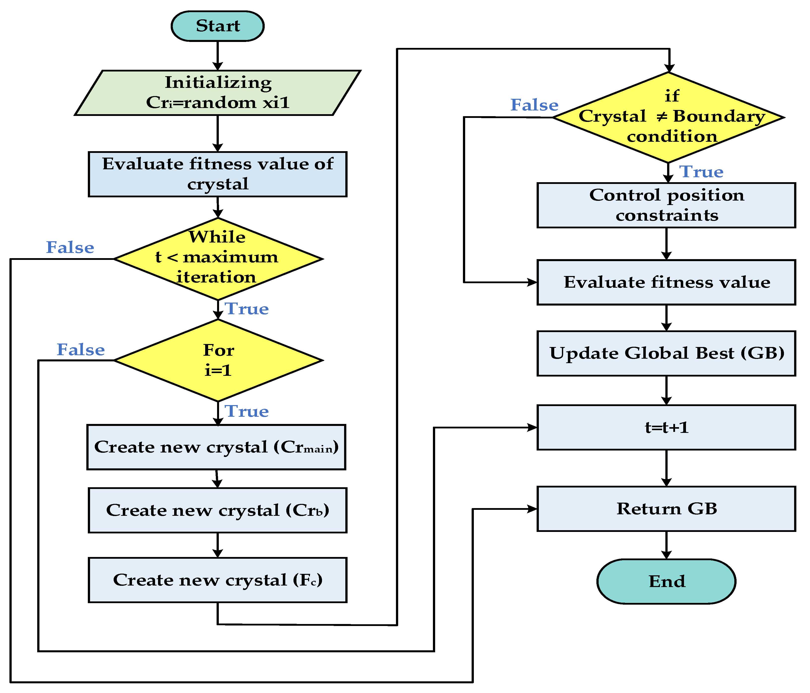
3. Exploitation and exploration are two key elements of metaheuristics, and they should be mentioned, and it has been examined in the equation from (4) to (7), in which global and local searches are carried out at the same time. To cope with the variable solution
violating variables’ boundary requirements, a mathematical flag is constructed, which requires an adjustment in the boundary for the violating variable for
beyond the variables range. The ending criterion is based upon the maximum iteration number after which the process of optimization ended after the iterations of the fixed number. The step-by-step Algorithm of the CryStAl is represented in the flow chart illustrated in
Figure 6.
5. Implementation of Crystal Structure Algorithm in Selective Harmonic Elimination
In pulse width modulation (PWM) method, the square output is chopped into several numbers is the basic idea of this strategy. The chopping time is proportional to a set of inverters switching angles acquired by suitable off-line computations. The inverter bridge switches are turned OFF and ON with a proper distribution of switching angles. The inverter’s output waveform is adjusted for reducing lower-order harmonics. Invariance to carrier-based pulse width modulation techniques, that identify the instant of switching by comparing reference and carrier waveforms directly. The exact prominence of switching instants is enumerated in the SHE method in accordance with the fundamental component desired and the component of harmonic to be eradicated. The number of switching angles is usually kept minimal to keep the computations lucid due to the complexity of the equation to be tackled to locate instants of switching. This has added benefit in minimizing switching losses of converter and instants of switching are calculated offline.
According to many studies, the SHE pulse width modulation (SHE-PWM) technique is the best PWM strategy. It efficiently decreases the harmonic content from the inverter output and eliminates certain lower-order harmonics to provide a higher-quality spectrum. As a result, it has been widely used in power electronic controllers. In the last few years, a slew of related strategies has been proposed. The main idea is to place notches at particularly selected PWM waveform sites, and the inverter will change direction several times per half cycle to manage the output waveform of the inverter suitably [
8]. SHE-PWM has sparked a lot of research interest since its inception. It is being developed for a variety of applications specifically for high-power converters and high-voltage, where losses of switching are a key concern, and lowering them is critical. SHE-PWM approaches are hinged on the decomposition of the PWM current/voltage waveform utilizing Fourier analysis and are solely dependent on the formulation and attributes of the waveform. In the technical literature, various waveform formulations have been explored and analyzed, which include unipolar, bipolar, and PWM multilevel or stepped waveform. Waveform features like symmetry and the number of voltage levels and amplitude are likewise important in analysis and play an important part in establishing a solution.
The key challenge is to find an analytical solution for the SHE-PWM waveforms. The choice for an appropriate equation-solving algorithm or approach is significantly influenced by the waveform’s formulation. To get the switching angles for various SHE-PWM waveforms, a variety of solving methodologies, such as iterative approaches, resultant theory, and optimization techniques have been developed. The implementation of SHE-PWM has been expanded to hybrid multilevel and various multilevel converters for a variety of applications. Because of the large number and variety of multilevel converters, each topology requires a unique implementation to realize the potential benefits of SHE-PWM for that converter [
8].
Switching Angle Calculation
To generate N levels of symmetrical quarter-wave output, (N − 1)/2 switching angles are necessary. For five, seven, and nine levels, two, three, and four angles are required respectively. Seven-level output voltage has been shown in
Figure 7 as an instance. Furthermore, every quarter cycle requires ‘
n + 1’ firing angles to remove the ‘
n’ number of harmonics in the SHE technique. As a result, only one (5th order) harmonic can be eliminated in five-level, two (5th & 7th order) in seven-level, and three (5th, 7th, & 11th order) in nine-level.
The Fourier series provides the equation for the above seven-level waveforms. Because the symmetry of the above seven-level waveforms is unusual,
For the quarter-wave symmetry
where,
E1 =
Vdc,
E2 = 2
Vdc,
E3 = 3
VdcFor
K (
K = (
N − 1)/2) Switching angles
For five levels output,
K = 2
The required firing angle for which the fifth, seventh, and eleventh harmonics will be eliminated can be computed by equating , to zero. CryStAl has been used in this paper to solve these non-linear equations. This gives the different values of α for different output voltage levels. This gives α1 and α2 equals 29.04° & 64.96° for five-level output. α1, α2 and α3 equals 20.40°, 51.72° & 64.67° for seven levels output and α1, α2, α3 and α4 equals 30.29°, 43.75°, 57.83° & 67.90° for nine levels output.
6. Simulation Results
The simulation for cascaded H-bridge multilevel inverter employing the CryStAl has been carried out in MATLAB/SIMULINK environment. Optimization algorithm has been compiled to evaluate the firing angles of the switches of asymmetrical CHB-MLI model. This model has been used to generate an output voltage having the desired number of voltage levels, which may be five-level, seven-level, or nine-level. Two H-bridges are connected in a cascaded manner to generate different voltage levels as shown in
Figure 3. Two voltage sources of unequal magnitude have been employed to achieve this. The magnitude of these sources is in a proportion of 1:3, whose combination either by addition or subtraction can generate five, seven, and nine levels. IGBT has been used as the switch whose switching pulse is provided with the repeating sequence block. The switching times or firing angles of the IGBTs have been evaluated by solving the non-linear transcendental equation which is shown in the equations from 14 to 21. The specifications of the components/parameters are mentioned in
Table 1. Numerous optimization techniques can be used to calculate the firing angle. The required firing angle for which the fifth, seventh, and eleventh harmonics will be eliminated can be computed by equating
,
to zero. α
1 and α
2 for five-level output can be evaluated by equating Equations (14) and (15) to zero. α
1, α
2, and α
3 for seven-level output can be calculated by equating equations from 16 to 18 to zero. Similarly, α
1, α
2, α
3, and α
4 for nine-level output can be obtained by equating equations from 19 to 22 to zero. Here, CryStAl has been employed to get the optimized angle. This gives the optimized value of α for different output voltage. This gives α
1 and α
2 equals 29.04° & 64.96° for five-level output. α
1, α
2 and α
3 equals 20.40°, 51.72° & 64.67° for seven levels output and α
1, α
2, α
3 and α
4 equals 30.29°, 43.75°, 57.83° & 67.90° for nine levels output. Different sets of firing angles at different modulation indices are evaluated. The variation of firing angles at different modulation index (varying from 0 to 1) for five-levels (α
1 and α
2), seven-levels (α
1, α
2, and α
3), and nine-levels (α
1, α
2, α
3, and α
4) have been plotted and illustrated in
Figure 8,
Figure 9 and
Figure 10 respectively. The output voltage and current at the terminal of resistive load and corresponding FFT for the five, seven, and nine levels are respectively shown in
Figure 11,
Figure 12 and
Figure 13. Moreover, selective harmonics i.e., 5th harmonics, 5th, and 7th harmonics, 5th, 7th, and 11th harmonics are respectively eliminated for the above-mentioned levels.
The behavior of dynamical load with both R and RL load is also observed. With R load only, the initial load resistance R is 25 Ω which changes to 50 Ω at 0.06 s. This load again changes back to the initial value of 25 Ω at 0.12 s. The performance of the inverter for five, seven, and nine levels with only R load change are shown in
Figure 14,
Figure 15 and
Figure 16 respectively. The same for the dynamical RL load have been shown in
Figure 17,
Figure 18 and
Figure 19 respectively, where the initial load impedance Z (which is equal to R + jX
L, where X
L is the inductive reactance) is 25.44 Ω which changes to 50.22 Ω at 0.06 s. This load again changes back to the initial value 25.44 Ω at 0.12 s. According to Ohm’s law, the current flowing through a conductor is directly proportional to the applied voltage while all the physical condition remains the same. From Ohm’s Law, I =
. It is obvious from these figures that the value of current increases with a decrease in the value of impedance and vice-versa. Moreover, the current waveform with the RL load is smoother than the current waveform with the R load only.
THD Comparison
A comparison of the THD using the Differential Evolution (DE), Genetic Algorithm (GA), and Crystal Structure Algorithm (CryStAl) for five-level, seven-level, and nine-level has been done and depicted in
Figure 20,
Figure 21 and
Figure 22 respectively. These plots show the variation of THD with a modulation index varying from 0.2 to 1.
In the case of five-level, it can be observed that the THD is lesser for CryStAl with a modulation index less than 0.43 and between 0.5 to 0.6. Afterward, the THD is the same for all the algorithms. For seven-level, the THD is lesser for CryStAl with a modulation index in the range 0.46 to 0.62. Afterward, the THD is the same for all the algorithms just like the five-level. Likewise, the THD is lesser for CryStAl with a modulation index in the range of 0.42 to 0.7 for nine-level. Again, the THD become almost the same for all the algorithm just like the five-level and seven-level for the rest modulation index. From the above statement, it is obvious that the range of the modulation index in which the CryStAl is more effective increases with an increase in the number of output levels while showing a performance similar to the other two techniques in the other ranges.
It’s obvious that the same selective harmonic has been eliminated using all these methods, but the THD is sufficiently improved in a wide range of modulation index employing CryStAl. Moreover, CryStAl is simple and parameter-free. Hence this algorithm is very effective in terms of simplicity and output THD and thus can be used in many domestic and industrial applications with both low and high number of output levels.
7. Hardware Implementation
The simulation results have been experimentally validated in the laboratory on a single-phase cascaded H-bridge multilevel inverter prototype.
Figure 23 shows the laboratory hardware setup consisting of two H-bridges which have been designed by employing 8 IGBTs (FGA25N120ANTDTU) with voltage & current ratings of 6000 Volts and 50 A respectively. The lower and upper H-bridge has been fed using asymmetrical confirmation employing two voltage sources of 60 V and 180 V. Digital signal controller TMS320F28335 (Texas Instruments) generates the control signal based on the stored firing angles for gate drives to operate IGBTs. The firing angles have been evaluated by using the CryStAl for certain modulation indices. The switching pulses are then transferred to the gates of IGBT through a TLP-250 optocoupler for insulating the IGBT from the DSP. Tektronix TPS 2024 oscilloscope has been used for measuring the output voltage and current waveform along with the corresponding harmonic. The specifications of the components used in hardware are mentioned in
Table 2.
Certain controlling techniques are employed to improve the performance and the quality of the output power of MLI. This can be achieved by eliminating the distinct lower-order harmonics by determining the optimum switching angles using certain SHE techniques. CryStAl based SHE technique has been used in the CHB-MLI for eliminating the specific harmonics in the five, seven, and nine-level output voltage.
Figure 24 illustrates the output and harmonic profile of the five-level MLI, in which 5th harmonics have been eliminated. The peak-to-peak voltage is 100 V. The RMS voltage and current are 38.05 V and 1.33 A respectively. 5th and 7th harmonics have been eliminated in seven-level MLI whose output and harmonic profile are depicted in
Figure 25. The peak-to-peak voltage is 154 V. The RMS voltage and current are 49.39 V and 6.42 A respectively. In a nine-level inverter, 5th, 7th, and 11th harmonics have been eliminated and its harmonic and output voltage and current profile are shown in
Figure 26. The peak-to-peak voltage is 137 V. The RMS voltage and current are 48.2 V and 3.75 A respectively. Moreover, the THD-F is 10.1%. It is clear from the experimental results that the 5th harmonics in five levels, 5th and 7th harmonics in seven-level and 5th, 7th, and 11th harmonics in nine-level MLI have been effectively eliminated and reducing the THD. Thus, improving the effectiveness of the CHB-MLI and reducing the need for the filters.
8. Conclusions
In this paper, the CryStAl has been used for eliminating the undesired harmonics from the output of a CHB-MLI. This helps in evaluating the optimum switching angle by solving the non-linear transcendental equation which helps in eliminating the lower-order harmonics and therefore improving the THD of the output voltage. This gives the optimized value of α for different output voltage. This gives α1 and α2 equals 29.04° & 64.96° for five-level output. α1, α2 and α3 equals 20.40°, 51.72° & 64.67° for seven levels output and α1, α2, α3 and α4 equals 30.29°, 43.75°, 57.83° & 67.90° for nine levels output. The removal of low-order harmonics in 5 levels, 7 level, and 9 level inverters using CryStAl based SHE technique has been described and evaluated. CryStAl can be highly convenient and worthwhile for all levels of symmetrical and asymmetrical multilevel inverters. In this algorithm, both the local and global searches are carried out the at same time. Additionally, the computational complexity of this algorithm is less than many other metaheuristic algorithms. CryStAl is a simple and parameter-free algorithm that doesn’t require the determination of any internal parameter during the optimization process. From the simulation result, it is obvious that the crystal structure algorithm is very effective and excels the other metaheuristic algorithm as mentioned in the THD comparison section. The 5th harmonics, 5th, and 7th harmonics, and 5th,7th, and 11th harmonics have been effectively removed respectively from five, seven, and nine-level output. The elimination of these selective harmonics resulted in a reduction in the THD and thus improves the effectiveness and performance of the MLI. This can also help in reducing the need for a filter circuit. The overall performance of CHB-MLI with the optimal switching angles for a certain number of the output voltage levels has been validated using the experiment result. It can be concluded that the CryStAl works perfectly and effectively with certain modulation indices in the elimination of particular lower-order harmonics from the output voltage waveform. Hence, the CryStAl for CHB-MLI can be effectively used in many applications like electric vehicles and solar PV systems.


 ,
, 


