Article

Research on Control Strategy of Isolated DC Microgrid Based on SOC of Energy Storage System

School of Mechanical, Electrical and Information Engineering, Shandong University, Weihai 264209, China
*
Author to whom correspondence should be addressed.
Electronics 2021, 10(7), 834; https://doi.org/10.3390/electronics10070834
Submission received: 15 March 2021 / Revised: 26 March 2021 / Accepted: 27 March 2021 / Published: 31 March 2021
(This article belongs to the Special Issue Control of Microgrids)

Abstract

:
With the rapid development of renewable energy technologies, islanded DC microgrids have received extensive attention in the field of distributed power generation due to their plug-and-play, flexible operation modes and convenient power conversion, and are likely to be one of the mainstream structures of microgrids in the future. The islanded DC microgrid contains multiple distributed power generation units. The battery energy storage system (BESS) is the main controlled unit used to smooth power fluctuations. The main parameter of concern is the state of charge (SOC). In order to maintain the stability of the microgrid, this paper takes the islanded DC microgrid as the research object and designs a control strategy based on the SOC of the BESS. Additionally, in the control strategy, the BESS’s energy balance control strategy and the microgrid’s operation control strategy are emphatically designed. The designed BESS control strategy adjusts the droop coefficient in real time according to the SOC of the battery energy storage unit (BESU), and controls the charge and discharge power of the BESU to achieve the SOC balance among the BESUs. The microgrid operation control strategy takes the energy storage system (ESS) as the main controlled unit to suppress power fluctuations, and distributes the power of distributed power sources according to the SOC of the BESS to achieve power balance in the microgrid, and control the DC bus voltage fluctuation deviation within 4.5%.

1. Introduction

Recently, in the process of social and economic development, problems of energy shortage and environmental pollution have become more and more serious. The development and utilization of traditional fossil fuels has increased the greenhouse effect, and the emitted greenhouse gases have a huge impact on the atmosphere. At the same time, due to the improper disposal of burning waste, it causes serious pollution of water re-sources and affects people’s lives. Under the urgent need for environmental governance and energy supply, many countries have begun to conduct research on pollution-free, high-safety and sustainable renewable energy [1].
Due to geographical restrictions, remote areas or islands cannot be powered by large power grids, and islanded microgrids are generally used to provide power. An isolated DC microgrid refers to a grid system that is not connected to the external grid, operates away from the main grid for a long time, and is only independently powered by distributed micropower sources in the microgrid [2]. An islanded microgrid generally includes a variety of distributed power sources, energy storage systems (ESSs), and various powered electronic devices. There is only a DC bus in the islanded DC microgrid, and distributed power sources and loads are connected to the DC bus through power electronic device. The topological structure of the islanded DC microgrid is shown in Figure 1.
With the development and progress of science and technology, more and more distributed renewable energy sources are being incorporated into the power grid. In order to maintain the stable and efficient operation of the DC microgrid, effective control strategies need to be formulated [3]. The control of the traditional DC microgrid mainly focuses on the stability of the bus voltage, and there is little research on the control strategy of the ESS. In the future, as the scale of small and medium-sized microgrids increases, the requirements for the control operation and control strategies of DC microgrids will become higher and higher. Therefore, research on the energy storage control strategy and the control operation of the DC microgrid is an indispensable part of the future research content on the DC microgrid.
Renewable energy power generation in an islanded DC microgrid is intermittent and fluctuating, and it is necessary to coordinate and control the battery in the renewable energy and ESS to ensure the reliability and stability of the microgrid [4]. The state of charge (SOC) is an important indicator of battery performance. Obtaining the accurate SOC of the energy storage battery is of important for the service life and secure operation of the energy storage battery [5]. There are a large number of renewable distributed power generation devices and loads in the islanded DC microgrid, and multiple battery energy storage systems (BESS) are usually configured to ensure the reliable power supply of DC microgrid for the loading and stable operation of DC microgrid. Due to the difference in the initial capacity and aging degree of the BESS, the SOC of a certain BESS will reach the limit ahead of time and exit the DC microgrid. When the remaining BESS capacity is not enough to support the operation of the DC microgrid, the DC microgrid system will collapse [6]. Therefore, it is necessary to design a BESS control strategy to complete the SOC balance of each energy storage unit (ESU), improve the capacity utilization rate of the BESS, and ensure the stable operation of the DC microgrid.
The BESS is essential for the safe operation and reliable power supply of the DC microgrid. During grid-connected operations, the BESS acts as a buffer unit to smooth the voltage fluctuations on the DC bus and maintain stable operation of the DC microgrid [7]. As operating off-grid, BESS acts as a backup energy source. When the system energy overflows, it absorbs the excess energy in the system, and when the system energy is insufficient, it outputs energy to the system [8]. The ESS stabilizes the power fluctuations in the microgrid through the charge or discharge of the battery, and maintains stability of DC bus voltage. The realization of multi-BESS’s SOC equalization control strategy can complete reasonable control of the charge and discharge rate between BESSs, prevent BESS overshoot and overdischarge, and extend the service life of the BESS [9].
The DC microgrid is composed of distributed power sources, loads, energy storage device and power electronic converters. Depending on whether the grid-connected converter is connected to the grid or not, it can be divided into grid-connected mode and off-grid mode. Since the DC microgrid does not have the problems of reactive power, frequency and phase synchronization, the stability of the DC bus voltage has become the only criterion to measure the stability of the DC microgrid [10]. In order to maintain the stability of the DC bus voltage, it is necessary to comprehensively consider the operating conditions of each distributed unit in the DC microgrid, and use the corresponding control strategy to coordinate and control its operation, to ensure completely stable and efficient operation of microgrid system. Through reasonable control of the microgrid, transmission loss can be reduced in terms of transmission [11]; in terms of power system, the quality, efficiency and reliability of microgrid power supply can be improved [12]; in terms of security, the power system can offer improved energy security [13].
For the BESS balance control strategy, the BESS bidirectional converter usually uses the traditional droop control to accomplish power balance in the microgrid [14,15,16], but when the multi-BESS bidirectional converter adopts the traditional droop control, SOC balance control between BESS cannot be achieved. Jones et al. provide information about the use of a single BESS for the traditional droop control in order to complete added the SOC the coordinated control of the variable droop coefficient and complete the consistent SOC of the BESS during the charging and discharging process [17], but did not consider the droop coefficient limit. When the coefficient changes with the SOC, it may exceed the allowable range, thereby threatening the safe and reliable operation of the system. In order to solve the problem of the droop coefficient limit, Lu et al. established a connection between the droop coefficient of BESS and the SOC through a function. The droop coefficient can be adaptively changed with the SOC within the allowable range, so as to achieve the purpose of reasonable power allocation and balanced multienergy storage’s SOC [18]. Although this method solves the problem of the droop coefficient limit, and achieves the effect of the SOC consistency of the BESS of equal capacity, the coordinated control of the SOC consistency of the BESS of different capacity remains to be studied. In addition, the coordinated control of the ESS through droop control will cause the deviation of the bus voltage, so the problem of restoring the bus voltage stability also needs to be considered [19,20].
For the operation control strategy of DC microgrid, Bracale et al. proposed a decentralized control strategy for DC microgrid [21]. This strategy aims at minimizing energy costs and achieves optimal control of the energy costs, but does not consider the quality of the DC microgrid power supply. Wen et al. proposed a distributed control strategy [22,23]. The main purpose of the designed control strategy is to ensure the reliability of the microgrid by keeping DC bus voltage constant and setting the priority of control unit. Mohammadi et al. proposed a distributed adaptive droop control strategy for the problem of bus voltage drop caused by traditional droop control [24]. This strategy completes bus voltage regulation and power distribution among distributed energy sources, and reduces the fluctuation of the bus voltage to a certain extent. Morstyn et al. and Chen et al. proposed a unified distributed control strategy for the operation control of the DC microgrid [25,26]. The distributed controller is integrated into the DC microgrid ESS to accomplish energy balance. The strategy reduces the complexity of the communication network in the DC microgrid. In ref. [27] a general decentralized control strategy for DC microgrid was designed. The proposed control strategy is based on DC bus voltage to achieve a maximum power output of renewable energy. This control strategy regulates the distributed power supply through a local controller. There is no need for communication between the controllers, and the construction cost is low, but this control strategy does not solve the problem of voltage fluctuations on the DC bus.
Based on the above problems, the BESS control strategy and microgrid operation control strategy based on BESS’s SOC are designed in this paper. The designed control strategy of the BESS completes the SOC balance among the BESUs. The designed microgrid operation control strategy completes the power balance in the microgrid, and the DC bus voltage is stabilized.
The rest of the article is shown below. In Section 2, the control strategy of the energy storage system is researched. In Section 3, the operation control strategy of the islanded DC microgrid based on the SOC of the energy storage system is designed. In Section 4, the islanded DC microgrid control strategy simulation is built in MATLAB/Simulink and the simulation results are discussed. In Section 5, the results are summarized.

2. Control Strategy of BESS

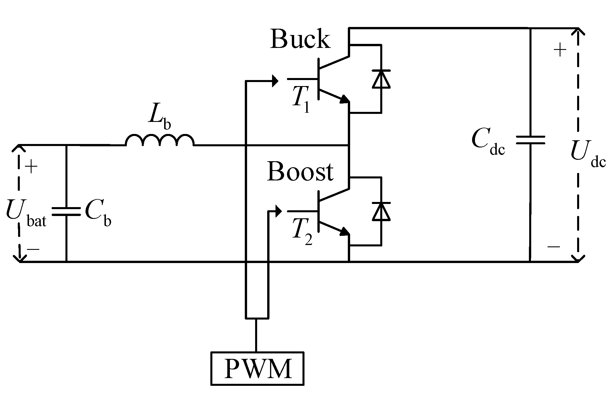
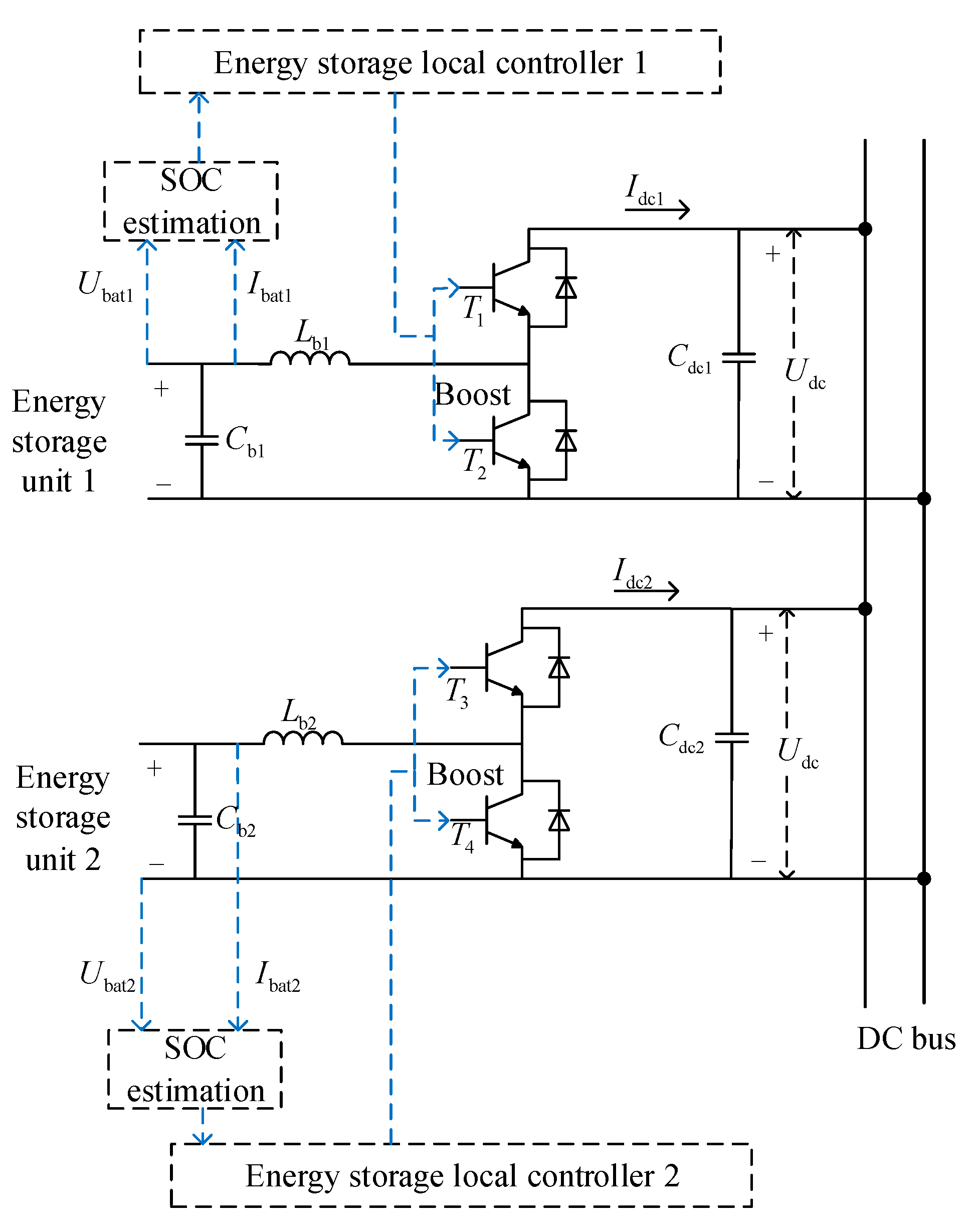
2.1. BESS’s Interface Converter

In islanded DC microgrids, the ESS plays an important role in suppressing power fluctuations in the microgrid. The bidirectional DC/DC converter connects the ESS with the DC bus, controls the charge or discharge of the energy storage battery, and completes the bidirectional flow of the energy. The bidirectional DC/DC converter is divided into isolated type and nonisolated type. The isolated bidirectional DC/DC converter can achieve a high voltage transformation ratio, but the cost is relatively high and the structure is complicated. The nonisolated bidirectional DC/DC converter has a simple structure and high reliability, and is suitable for use in ESSs in small microgrids. Common nonisolated bidirectional DC/DC converters include Buck/Boost bidirectional DC/DC converters, half-bridge bidirectional DC/DC converters, and Cuk bidirectional DC/DC converters. Buck/Boost bidirectional DC/DC converter has the advantages of simple structure, high efficiency, strong reliability and easy control. Therefore, this article chooses Buck/Boost bidirectional DC/DC converter to complete the charge and discharge control of the energy storage battery. The structure of Buck/Boost bidirectional DC/DC converter is shown in Figure 2.
There are two switching tubes T 1 and T 2 in the Buck/Boost bidirectional DC/DC converter. The two switching tubes are controlled by the PWM signal, and the bidirectional DC/DC converter can be divided into Buck working state and Boost working state. When the power overflows in the islanded DC microgrid, the ESS has to be charged. At the moment, the PWM signal controls the bidirectional DC/DC converter to be in the Buck working state to charge the ESS. When the power is insufficient in the islanded DC microgrid, the ESS must release power. At this time, the PWM signal controls the bidirectional DC/DC converter to be in the Boost working state to control the discharge of the ESS.

2.2. Traditional ESS’s Control Strategy

The distributed control method based on voltage droop characteristics has the advantages of simple structure, plug-and-play, easy operation, etc., and is widely used in the control strategy of ESSs. U-I droop control is in the control of the DC bus voltage, by introducing current feedback and virtual resistance, and then correcting the reference value of the bus voltage, achieving a compromise between the accuracy of the differential control and the effect of power balance. U-I droop control is to add U-I droop characteristic curve control at the front end of the voltage and current double closed-loop control. The U-I droop characteristic curve is shown in Figure 3.
The expression of the U-I droop characteristic curve shown in Figure 3 is:
U d c - i = U d c - r e f I d c - i R d r o o p - i
where, U d c - r e f is DC bus reference voltage; U d c - i is output voltage of the converter of the i -th ESU; I d c - i is output current of converter of the i -th ESU; R d r o o p - i is the droop coefficient of the UI droop characteristic curve of the i -th ESU.
Through U-I droop control, all ESUs in the islanded DC microgrid jointly complete the adjustment of the DC bus voltage, and each ESU assumes the amount of change in the DC bus voltage according to its own U-I droop coefficient. It can be seen from Figure 3 that in the U-I droop control, the ESU with a large droop coefficient produces a larger voltage drop, but the ESU has a better adjustment effect on the current; The ESU with a small droop coefficient produces a small voltage drop, but the ESU has a poor adjustment effect on the current. It can be concluded that, during U-I droop control, the difference in voltage control accuracy is sacrificed to achieve the adjustment of the current size of the ESU, and the effect of current sharing is achieved.
Ignoring the influence of transmission resistance, the block diagram of U-I droop control of a single ESU is shown in Figure 4.
Using the control process shown in Figure 4, the PWM signal that controls the Buck/Boost bidirectional DC/DC converter is finally obtained, so as to complete the adjustment of the charge and discharge current of the ESU.

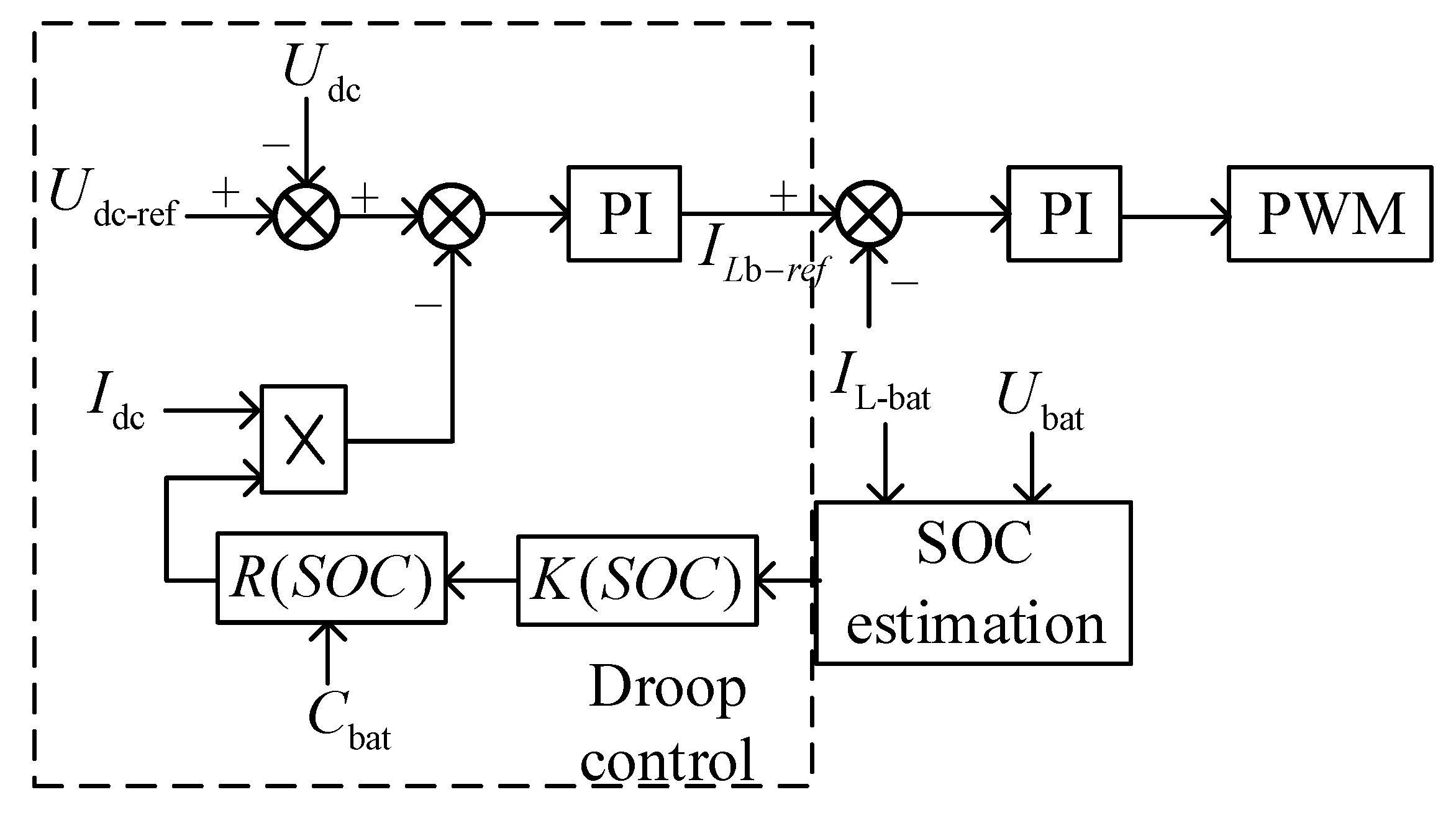
2.3. Balance Control Strategy of ESS Based on SOC

In islanded DC microgrids, the ESS consists of multiple ESUs. When the traditional droop control is used to control the charge and discharge of each ESU, since the droop coefficient is fixed, the SOC balance between the ESUs cannot be achieved, which will cause the overcharge or overdischarge of a certain ESU, which will affect the stable operation of the islanded DC microgrid.
The improved droop control strategy is to combine the droop coefficient with the SOC of the ESU. The energy storage local controller adjusts the droop coefficient in the droop control strategy of each ESU in real time according to the SOC of each ESU. The structure of the parallel ESU in the islanded DC microgrid is shown in Figure 5.
According to Figure 5, the expression for the droop control of the ESU can be obtained as:
U d c - i = U d c - r e f I d c - i R i ( S O C )
where, R i ( S O C ) is the sag coefficient of the i -th ESU.
Ignoring the influence of the resistance of the transmission line on the voltage, the corresponding relationship between the sag coefficient and the output current of each ESU is:
I d c - 1 R 1 ( S O C ) = I d c - 2 R 2 ( S O C ) = = I d c - i R i ( S O C )
From Equation (3), it can be concluded that the droop coefficient of the ESU is inversely proportional to the output current of the ESU converter. In order to achieve the SOC balance of the ESU, each ESU needs to determine the droop coefficient according to its own SOC value. During the charging process, the ESU with a large SOC value has a larger sag coefficient and lower absorbed power; an ESU with a smaller SOC value has a smaller sag coefficient and higher absorbed power. During the discharging process, the ESU with a large SOC has a smaller droop coefficient and releases greater power; an ESU with a smaller SOC value has a greater droop coefficient and releases less power. In the ESS, there is no guarantee that the capacity of each ESU is the same. Therefore, it is also necessary to consider the impact of the capacity of the ESU on the sag coefficient. During the charging or discharging process, the ESU with the larger capacity absorbs or releases more power, so as to prevent the ESU with the smaller capacity from exiting the working state early due to overcharging or overdischarging. The calculation formula of the droop coefficient considering the SOC of the ESU is:
R i ( S O C ) = C i D K i ( S O C )
K i ( S O C ) = { e S O C i 2 S O C ¯ 2 e ( S O C i 2 S O C ¯ 2 ) Charging Discharging
where, D is the convergence rate factor, C i is the capacity of the i -th ESU, and S O C ¯ is the average SOC value of the ESU.
The improved droop control not only considers the SOC of the ESU, but also introduces the capacity of the ESU into the calculation of the droop coefficient. On the basis of achieving the balance of the SOC of the ESU, the capacity utilization rate of the ESS is improved. The control flow diagram of the improved droop control is shown in Figure 6.
In the traditional droop control, in addition to the fixed droop coefficient that will affect the current sharing effect, the droop control will also cause the DC bus voltage to rise or fall during the charging and discharging process of the ESU. In order to solve the problem that the DC bus voltage deviates from the reference value to a certain extent caused by the droop control, on the basis of the improved SOC-based droop control, this paper designs a secondary compensation of the voltage to reduce the deviation of the bus voltage caused by the droop control. The secondary compensation formula of the DC bus voltage is:
U d c - i = U d c - r e f I d c - i R i ( S O C ) + Δ U i
Δ U i = ( K p + K i ) ( U d c - r e f U d c - i )
K i = k ( U d c - r e f U dc ) U d c - r e f R i ( S O C )
where, Δ U i is the secondary compensation amount of the DC bus terminal voltage of the i -th ESU; K p and K i are the adjustment parameters of the PI controller, and k is the adjustment factor of the dynamic adjustment parameters K i .
The block diagram of the secondary compensation control of the DC bus voltage is shown in Figure 7.

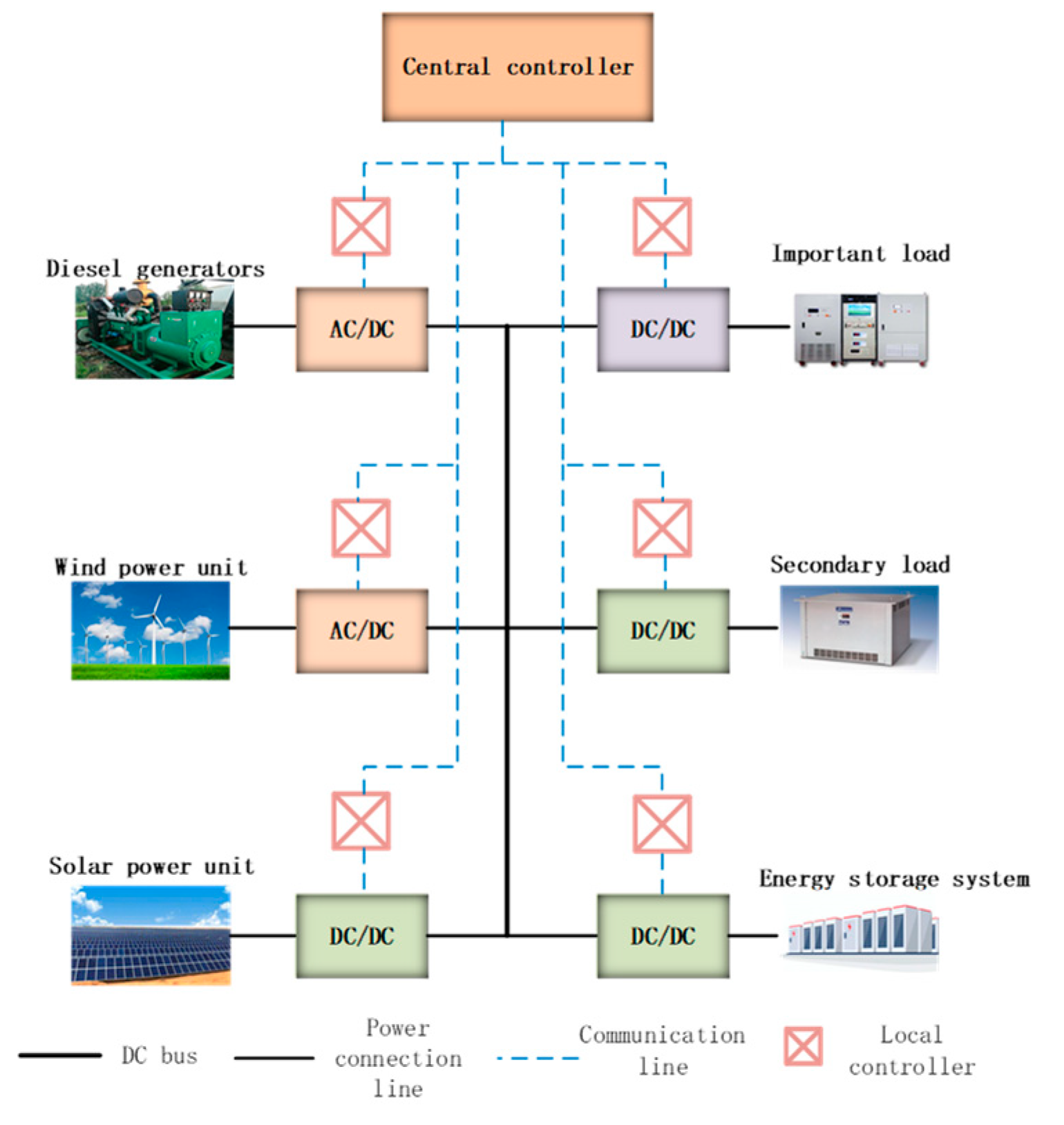
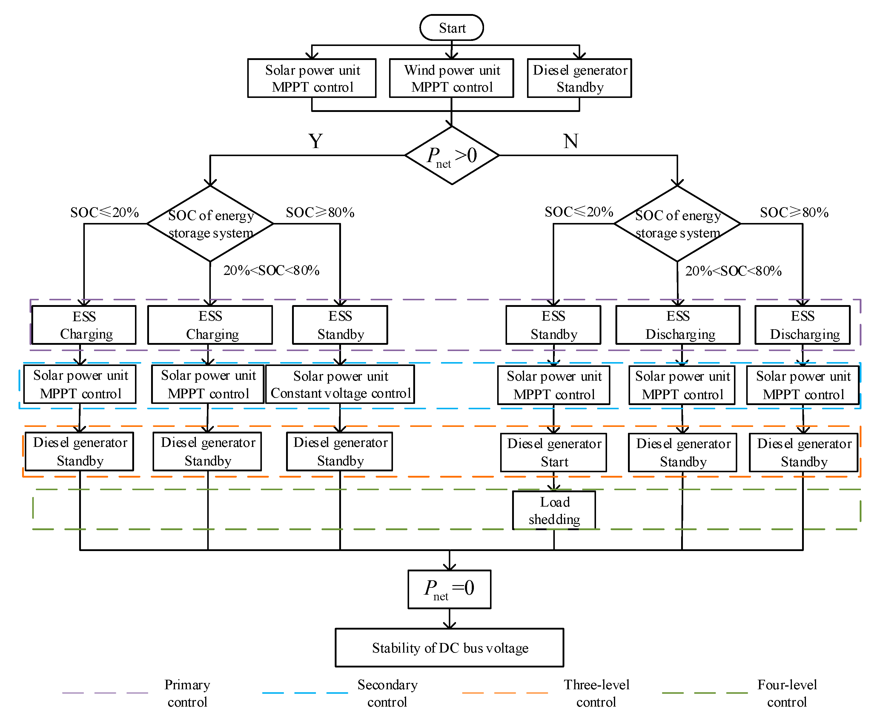
3. Control Strategy for the Operation of Isolated DC Microgrid

3.1. Control System of Islanded DC Microgrid

The control system of the islanded DC microgrid mainly includes the physical layer, device-level control and system-level control of islanded DC microgrid [28]. The control system of islanded DC microgrid is shown in Figure 8.
The device-level control mainly includes the control of the interface converters of distributed power sources, DC loads, and energy storage devices. The main control goal is that the local controller quickly controls the interface converters of each unit according to the instructions issued by the central controller, completes the power balance in the islanded DC microgrid, maintains the stability of DC bus, and guarantees the power supply of microgrid. The device-level control method mainly includes the Maximum Power Point Tracking (MPPT) control of solar power generation units and wind power generation units, the constant voltage control (CVC) of solar power generation units and diesel generators, and the charge and discharge control of ESUs in energy storage devices. The device-level control structure is shown in Figure 9.

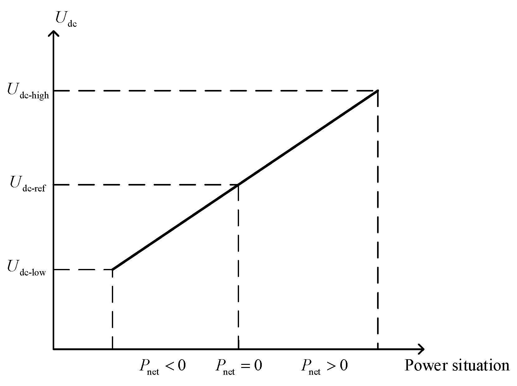
3.2. Operational Control Based on SOC of ESS

For completing power balance in the islanded DC microgrid and maintain the stability of the DC bus voltage. In this paper, an operation control strategy based on the SOC of the ESU will be used to control the islanded DC microgrid. The ESS is used as the main unit to smooth the power fluctuations in the microgrid, and other distributed power generation units are used as the secondary controlled units. The central controller coordinates the distribution of the power of each distributed microsource according to the ESS’s SOC and the power situation of the microgrid, and maintains the power balance in the microgrid.
In the islanded DC microgrid operation, in order to use renewable energy as much as possible for power supply, the solar power unit and wind power generation unit work at the MPPT for maximum power output at the initial moment, and diesel generators are used as backup energy sources.
The power P net of the islanded DC microgrid is defined as:
P net = P pv + P wf + P do + P bes P load
where, P pv is the output power of the solar power unit, P wf is the output power of the wind power unit, P do is the output power of the diesel generator, P bes is the power absorbed or released by the ESS; P load is the power absorbed by the load.
In islanded DC microgrid, because the DC bus is used to transmit electric energy, there is no need to consider the problem of reactive power, so the DC bus voltage can directly reflect the power situation in the microgrid [29]. The corresponding situation for power and bus voltage in an islanded DC microgrid is shown in Figure 10.
In Figure 10, U d c - r e f is the reference value of the bus voltage. In this paper, the reference value of the bus voltage is set to 450 V, and U d c - l o w U d c - h i g h is the allowable fluctuation range of the bus voltage. According to the requirements of the allowable deviation of the supply voltage, the DC bus voltage deviation range is the DC bus reference 7% of the value.
When the power in the islanded DC microgrid is balanced, the bus voltage corresponds to the reference value of the bus voltage. At the moment, the power of microgrid can be expressed as:
P pv + P wf + P do + P bes P load = 0
When the power in the islanded DC microgrid is lacking, the bus voltage is lower than the reference value of the bus voltage, and the power of the microgrid can be expressed as:
P pv + P wf + P do + P bes P load < 0
When the power in the islanded DC microgrid overflows, the bus voltage is higher than the reference value of the bus voltage, and the power of the microgrid can be expressed as:
P pv + P wf + P do + P bes P load > 0
In islanded DC microgrids, the energy storage device is the main controlled unit used to maintain the DC bus voltage, and the SOC of the ESS is an important basis for the microgrid’s control strategy and mode switching. According to the SOC of the ESS and the power situation in the islanded DC microgrid, the control strategy and working mode of the islanded DC microgrid are analyzed:
(1) SOC < 20%—at this time the SOC of the ESS reaches the lower limit and cannot be discharged. When P net < 0 , the power in the islanded DC microgrid is lacking. Since the ESS cannot work to smooth out power fluctuations, it is necessary to start the diesel generator to supply power at this time. When starting the diesel generator still cannot meet the load end demand, the secondary load should to be cut off at this time. When P net > 0 , the power in the islanded DC microgrid overflows, and the excess power is absorbed by the ESS.
(2) 20% < SOC < 80%—the ESS can be charged and discharged at this time. When P net < 0 , the power in the islanded DC microgrid is lacking. At this time, the ESS needs to be discharged to increase the input power. When P net > 0 , the power in the islanded microgrid overflows. At this time, the ESS needs to be charged to absorb the excess power.
(3) SOC > 80%—the ESS has reached the upper limit of SOC and cannot be charged. When P net < 0 , the islanded DC microgrid lacks power, and the ESS discharges to increase the output power. When P net > 0 , there is excess power in the islanded DC microgrid, and the ESS cannot be charged. Therefore, it is necessary to convert solar power units from MPPT control to CVC to maintain the power balance in the microgrid to achieve the stability of the DC bus voltage.
The control operation strategy of islanded DC microgrid is shown in Figure 11.
Using the operating control strategy shown in Figure 11, the central controller can divide the operating status of the islanded DC microgrid into six modes. The working status of the islanded DC microgrid is shown in Table 1.

4. Simulation and Discussion

To verify the effectiveness of control strategy designed in this article, an islanded DC microgrid control simulation was built in MATLAB/Simulink. According to the technical regulations for microgrid access to the power system, the power generation of the microgrid is generally based on the principle of local consumption, and each distributed power supply is configured based on the load power, and the continuous power supply to the load in the microgrid independent operation mode is not less than 2 h. Set the parameters of islanded DC microgrid simulation system as shown in Table 2.

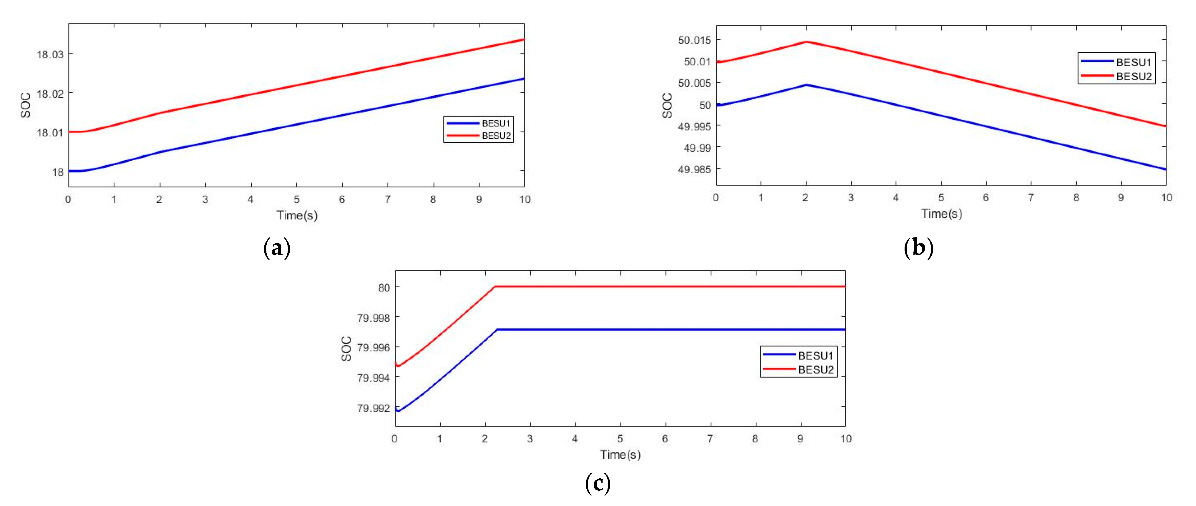
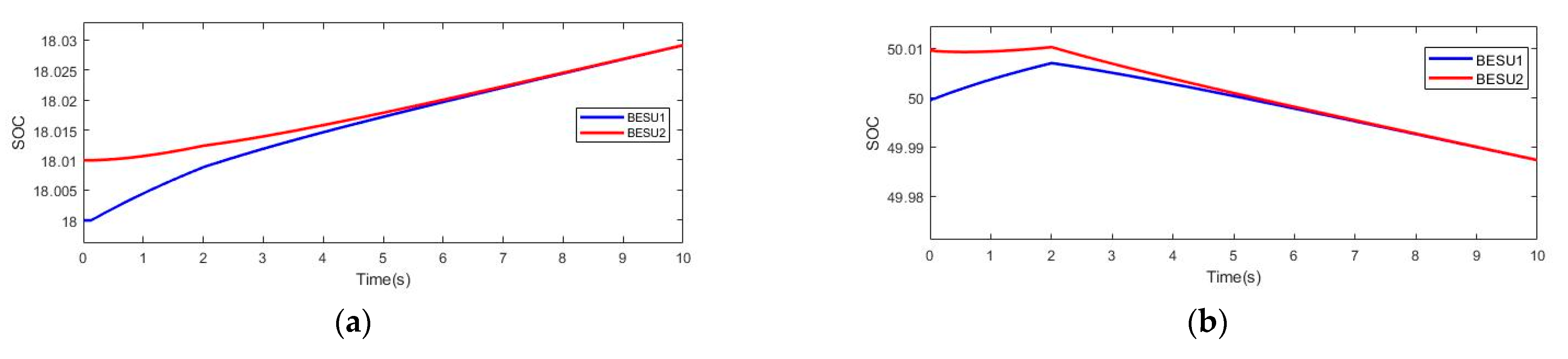
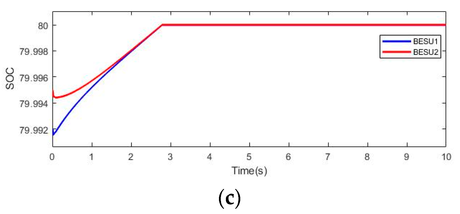
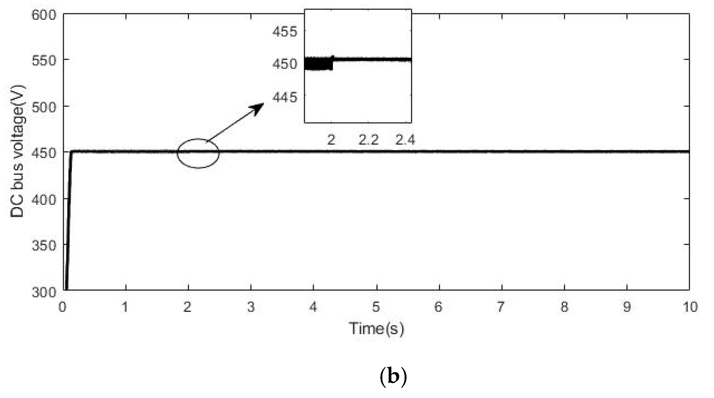
4.1. Simulation of the Control Strategy of the ESS

The ESS designed in this paper is composed of two ESUs. The simulation results of the traditional energy storage control strategy are shown in Figure 12, and the control strategy based on the ESU’s SOC are shown in Figure 13.
It can be seen from Figure 12a and Figure 13a that when the SOC of the ESU is lower than 20%, the ESU can only be charged. It can be seen from Figure 12b and Figure 13b that when the SOC of the ESU is in the range of 20–80%, the ESU can be charged and discharged. It can be seen from Figure 12c and Figure 13c that when the SOC of the ESU is greater than 80%, the ESU cannot continue to be charged and the ESS is in a standby state. Comparing Figure 12 and Figure 13, it can be concluded that the use of an ESS control strategy based on the SOC of the ESU can achieve the SOC balance of the ESU, thereby avoiding the exit of the ESS caused by a single ESU reaching the SOC threshold in advance.

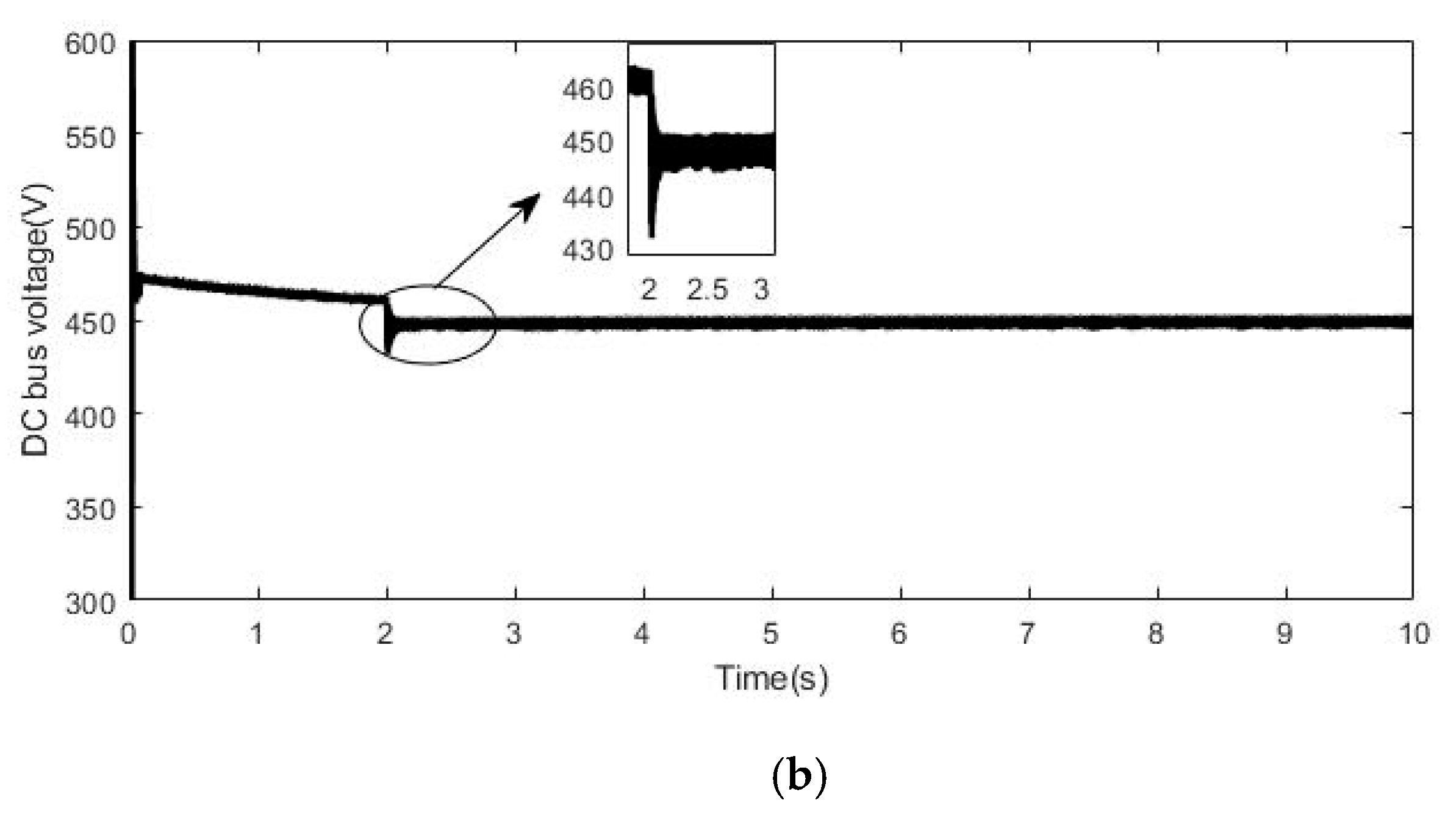
4.2. Operation Control Strategy of Microgrid

According to the SOC value of the ESS, it is divided into three situations for simulation verification.
(1) ESS’s SOC < 20%
At the beginning, on the power generation side of the distributed unit, both the solar power generation unit and the wind power generation unit work in MPPT mode. When t = 2 s, the intensity of light decreases and the output power of solar power unit decreases. At the moment, the power of microgrid is insufficient, and the central controller disconnects the secondary load. The simulation results of the operation control strategy of the islanded DC microgrid when the ESS’s SOC < 20% are shown in Figure 14.
It can be seen from Figure 14a that due to the reduced light intensity, the output power of the solar power generation unit decreases at t = 2 s. At the moment, the total power in microgrid is less than zero, the SOC of the ESS is less than 20%, and the ESS cannot be discharged. Under the control of the central controller, the diesel generator is started and the secondary load is disconnected to maintain the power balance in the microgrid. It can be seen from Figure 14b that the fluctuation range of the DC bus voltage is between 445–450 V. The fluctuation range of the bus voltage is controlled within 2%.
(2) 20% < ESS’s SOC < 80%
At the beginning, on the power generation side of the distributed unit, both the solar power generation unit and the wind power generation unit work in MPPT mode. When t = 2 s, the light intensity decreases and the output power of the solar power unit decreases. At this time, the ESS releases power into the microgrid to smooth out power fluctuations. The simulation results of the operation control strategy of the islanded DC microgrid when 20% < ESS’s SOC < 80% are shown in Figure 15.
Figure 15a shows that the output power of the solar power generation unit is reduced at t = 2 s due to the reduced light intensity. At this time, the energy storage system is discharged to maintain the power balance in the microgrid. Figure 15b shows that the DC bus voltage fluctuates between 430 V and 460 V at t = 2 s, and the fluctuation range of the DC bus voltage is controlled within 4.5%.
(3) ESS’s SOC > 80%
At the beginning, on the power generation side of the distributed unit, both the solar power generation unit and the wind power generation unit work in MPPT mode. When t = 2.8 s, the SOC of the ESS reaches the upper threshold, and the ESS cannot continue to be charged. In order to maintain the power balance in the microgrid, the solar power generation unit is converted to CVC to reduce the output power. The simulation results of the operation control strategy of the islanded DC microgrid when the ESS’s SOC > 80% are shown in Figure 16.
It can be seen from Figure 16a that the SOC of the ESS reaches the upper threshold t = 2.8 s and it cannot be charged. Due to the excess power in the microgrid at this time, the solar power generation unit is controlled by constant voltage to reduce the output power. It can be seen from Figure 16b that the DC bus voltage fluctuates at t = 2.8 s between 440–460 V, and the fluctuation range of the DC bus voltage is controlled within 2.3%.

5. Conclusions

In this paper, the control strategy of an islanded DC microgrid is researched, and the control strategy of islanded DC microgrid based on SOC of ESS is designed. First of all, the traditional ESS control strategy is analyzed, and the improvement is made on the basis of the traditional control strategy. The improved ESS control strategy completes the SOC balance between the ESUs. Then, based on the SOC of the ESS, under the control of the central controller, the ESS is used as the main controlled unit to suppress power fluctuations, and coordinate the control methods of the distributed power generation units to ensure the power balance of the DC microgrid. Finally, the islanded DC microgrid simulation model was built, and different microgrid operating modes were simulated in MATLAB/Simulink. The results of the simulation show that the ESS control strategy based on the SOC of the ESU designed in this paper can complete the SOC balance among the ESUs. The designed operation control strategy based on the SOC of the ESS can complete the smooth switching of the various modes and maintain the power balance in the microgrid. The fluctuation range of the DC bus voltage is controlled within 4.5% to realize the stable operation of the islanded DC microgrid.
The output power of the unit using renewable energy such as solar energy and wind power has volatility and randomness. If the power of the renewable energy generation unit can be predicted, the stability of the island DC microgrid will be stronger and the energy utilization rate will also be improved. Therefore, the prediction of the output power of the renewable energy generation unit will be the focus of the following research work.

Author Contributions

Conceptualization, J.L. and G.W.; methodology, J.L.; software, J.L.; validation, J.L., X.W. and Y.S.; formal analysis, Y.S.; investigation, G.W.; resources, Y.S.; data curation, G.W.; writing—original draft preparation, J.L.; writing—review and editing, J.L.; visualization, X.W.; supervision, Y.S.; project administration, J.L.; funding acquisition, Y.S. All authors have read and agreed to the published version of the manuscript.

Funding

The research received no external funding.

Acknowledgments

We gratefully acknowledge the technical assistance of DL850E ScopeCorder.

Conflicts of Interest

The authors declare no conflict of interest.

References

  1. Ahmed, D.; Ebeed, M.; Ali, A.; Alghamdi, A.S.; Kamel, S. Multi-Objective Energy Management of a Micro-Grid Considering Stochastic Nature of Load and Renewable Energy Resources. Electronics 2021, 10, 403. [Google Scholar] [CrossRef]
  2. Guo, J.; Chen, T.; Chaudhuri, B.; Hui, S.Y.R. Stability of Isolated Microgrids with Renewable Generation and Smart Loads. IEEE Trans. Sustain. Energy 2020, 11, 2845–2854. [Google Scholar] [CrossRef]
  3. Zhao, Z.; Zhang, J.; He, Y.; Zhang, Y.; Liu, M. Island DC microgrid hierarchical coordinated multi-mode control strategy. Energies 2019, 14, 3012. [Google Scholar] [CrossRef] [Green Version]
  4. Ould Amrouche, S.; Rekioua, D.; Rekioua, T.; Bacha, S. Overview of energy storage in renewable energy systems. Int. J. Hydrogen Energy 2016, 41, 20914–20927. [Google Scholar] [CrossRef]
  5. Misyris, G.S.; Doukas, D.I.; Papadopoulos, T.A.; Labridis, D.P.; Agelidis, V.G. State-of-Charge Estimation for Li-Ion Batteries: A More Accurate Hybrid Approach. IEEE Trans. Energy Convers. 2019, 34, 109–119. [Google Scholar] [CrossRef] [Green Version]
  6. Li, F.; Xie, K.; Yang, J. Optimization and analysis of a hybrid energy storage system in a small-scale standalone microgrid for remote area power supply (RAPS). Energies 2015, 8, 4802–4826. [Google Scholar] [CrossRef]
  7. Li, Z.; Xu, Y. Optimal coordinated energy dispatch of a multi-energy microgrid in grid-connected and islanded modes. Appl. Energy 2018, 210, 974–986. [Google Scholar] [CrossRef]
  8. Li, Y.; Yang, Z.; Li, G.; Zhao, D.; Tian, W. Optimal Scheduling of an Isolated Microgrid with Battery Storage Considering Load and Renewable Generation Uncertainties. IEEE Trans. Ind. Electron. 2019, 66, 1565–1575. [Google Scholar] [CrossRef] [Green Version]
  9. Huang, W.; Abu Qahouq, J.A. Energy Sharing Control Scheme for State-of-Charge Balancing of Distributed Battery Energy Storage System. IEEE Trans. Ind. Electron. 2015, 62, 2764–2776. [Google Scholar] [CrossRef]
  10. Kwon, M.; Choi, S. Control Scheme for Autonomous and Smooth Mode Switching of Bidirectional DC-DC Converters in a DC Microgrid. IEEE Trans. Power Electron. 2018, 33, 7094–7104. [Google Scholar] [CrossRef]
  11. Meng, W.; Wang, X.; Liu, S. Distributed load sharing of an inverter-based microgrid with reduced communication. IEEE Trans. Smart Grid 2018, 9, 1354–1364. [Google Scholar] [CrossRef]
  12. Basak, P.; Chowdhury, S.; Halder Nee Dey, S.; Chowdhury, S.P. A literature review on integration of distributed energy resources in the perspective of control, protection and stability of microgrid. Renew. Sustain. Energy Rev. 2012, 16, 5545–5556. [Google Scholar] [CrossRef]
  13. Song, X.; Lin, H.; De, G.; Li, H.; Fu, X.; Tan, Z. An energy optimal dispatching model of an integrated energy system based on uncertain bilevel programming. Energies 2020, 13, 477. [Google Scholar] [CrossRef] [Green Version]
  14. Marzebali, M.H.; Mazidi, M.; Mohiti, M. An adaptive droop-based control strategy for fuel cell-battery hybrid energy storage system to support primary frequency in stand-alone microgrids. J. Energy Storage 2020, 27, 101127. [Google Scholar] [CrossRef]
  15. Ríos, S.J.; Pagano, D.J.; Lucas, K.E. Bidirectional Power Sharing for DC Microgrid Enabled by Dual Active Bridge DC-DC Converter. Energies 2021, 14, 404. [Google Scholar] [CrossRef]
  16. Kim, D.E. Power flow study of low-voltage DC micro-grid and control of energy storage system in the grid. J. Electr. Eng. Technol. 2017, 12, 549–558. [Google Scholar] [CrossRef] [Green Version]
  17. Jones, A.J.; Weaver, W.W. Optimal droop surface control of dc microgrids based on battery state of charge. In Proceedings of the ECCE 2016 IEEE Energy Conversion Congress and Exposition, Milwaukee, Wisconsin, 18–22 September 2016. [Google Scholar]
  18. Lu, X.; Sun, K.; Guerrero, J.M.; Vasquez, J.C.; Huang, L. State-of-charge balance using adaptive droop control for distributed energy storage systems in DC microgrid applications. IEEE Trans. Ind. Electron. 2014, 61, 2804–2815. [Google Scholar] [CrossRef] [Green Version]
  19. Shuai, Z.; Fang, J.; Ning, F.; Shen, Z.J. Hierarchical structure and bus voltage control of DC microgrid. Renew. Sustain. Energy Rev. 2018, 82, 3670–3682. [Google Scholar] [CrossRef]
  20. Lee, J.O.; Kim, E.S.; Moon, S. Il Determining P-Q Droop Coefficients of Renewable Generators for Voltage Regulation in an Islanded Microgrid. Energy Procedia 2017, 107, 122–129. [Google Scholar] [CrossRef]
  21. Bracale, A.; Caramia, P.; Carpinelli, G.; Mancini, E.; Mottola, F. Optimal control strategy of a DC micro grid. Int. J. Electr. Power Energy Syst. 2015, 67, 25–38. [Google Scholar] [CrossRef]
  22. Wen, H.; Zhu, W. Control and Protection of DC Microgird with Battery Energy Storage System. In Proceedings of the 2016 IEEE International Conference on Power Electronics, Drives and Energy Systems (PEDES), Thiruvananthapuram, India, 14–17 December 2016; pp. 1–6. [Google Scholar]
  23. Wen, H.; Zheng, K.; Du, Y. Hierarchical coordinated control for DC microgrid with crowbar and load shedding control. In Proceedings of the 2017 IEEE 3rd International Future Energy Electronics Conference and ECCE Asia (IFEEC 2017—ECCE Asia), Kaohsiung, Taiwan, 3–7 June 2017; pp. 2208–2212. [Google Scholar]
  24. Mohammadi, J.; Badrkhani Ajaei, F. Improved Mode-Adaptive Droop Control Strategy for the DC Microgrid. IEEE Access 2019, 7, 86421–86435. [Google Scholar] [CrossRef]
  25. Morstyn, T.; Hredzak, B.; Demetriades, G.D.; Agelidis, V.G. Unified distributed control for DC microgrid operating modes. IEEE Trans. Power Syst. 2016, 31, 802–812. [Google Scholar] [CrossRef]
  26. Chen, M.; Ma, S.; Wan, H.; Wu, J.; Jiang, Y. Distributed control strategy for DC microgrids of photovoltaic energy storage systems in off-grid operation. Energies 2018, 11, 2637. [Google Scholar] [CrossRef] [Green Version]
  27. Mohammadi, J.; Ajaei, F.B. Versatile decentralised control of the DC microgrid. IET Smart Grid 2019, 2, 77–88. [Google Scholar] [CrossRef]
  28. Lin, P.; Zhang, C.; Wang, J.; Jin, C.; Wang, P. On Autonomous Large-Signal Stabilization for Islanded Multibus DC Microgrids: A Uniform Nonsmooth Control Scheme. IEEE Trans. Ind. Electron. 2020, 67, 4600–4612. [Google Scholar] [CrossRef]
  29. Xia, Y.; Yu, M.; Yang, P.; Peng, Y.; Wei, W. Generation-Storage Coordination for Islanded DC Microgrids Dominated by PV Generators. IEEE Trans. Energy Convers. 2019, 34, 130–138. [Google Scholar] [CrossRef]
Figure 1. Topological structure of islanded DC microgrid.
Electronics 10 00834 g001
Figure 2. Buck/Boost bidirectional DC/DC converter structure.
Electronics 10 00834 g002
Figure 3. U-I droop characteristic curve.
Electronics 10 00834 g003
Figure 4. U-I droop control of energy storage unit (ESU).
Electronics 10 00834 g004
Figure 5. Structure of parallel ESUs.
Electronics 10 00834 g005
Figure 6. Droop control of energy storage system (ESS) based on state of charge (SOC).
Electronics 10 00834 g006
Figure 7. Secondary compensation control of DC bus voltage.
Electronics 10 00834 g007
Figure 8. Control system of islanded DC microgrid.
Electronics 10 00834 g008
Figure 9. Device-level control structure.
Electronics 10 00834 g009
Figure 10. Correspondence between the power of the microgrid and the bus voltage.
Electronics 10 00834 g010
Figure 11. Operation control strategy of islanded DC microgrid.
Electronics 10 00834 g011
Figure 12. Simulation results of traditional ESS control strategy. (a) ESU’s SOC < 20%; (b) 20% < ESU’s SOC < 80%; (c) ESU’s Scheme 80.
Electronics 10 00834 g012
Figure 13. Simulation results of SOC-based ESU’s control strategy. (a) ESU’s SOC < 20%; (b) 20% < ESU’s SOC < 80%; (c) ESU’s SOC > 80%.
Electronics 10 00834 g013aElectronics 10 00834 g013b
Figure 14. Simulation results of operation control strategy when ESS’s SOC < 20%. (a) Power situation of microgrid; (b) DC bus voltage.
Electronics 10 00834 g014aElectronics 10 00834 g014b
Figure 15. Simulation results of operation control strategy when 20% < ESS’s SOC < 80%. (a) Power situation of microgrid; (b) DC bus voltage.
Electronics 10 00834 g015aElectronics 10 00834 g015b
Figure 16. Simulation results of operation control strategy when ESS’s SOC > 80%. (a) Power situation of microgrid; (b) DC bus voltage.
Electronics 10 00834 g016
Table 1. Working status of islanded DC microgrid.
StatusMode 1Mode 2Mode 3Mode 4Mode 5Mode 6
Micro Source
SOC<20%<20%20–80%20–80%>80%>80%
P net <0>0<0>0<0>0
ESSStandbyChargingDischargingChargingDischargingStandby
Solar power unitMPPTMPPTMPPTMPPTMPPTCVC
Wind power unitMPPTMPPTMPPTMPPTMPPTMPPT
Diesel generatorsStartStandbyStandbyStandbyStandbyStandby
LoadCut loadAll loadAll loadAll loadAll loadAll load
Table 2. Basic parameters of islanded DC microgrid simulation.
ParameterSymbolValueUnit
DC bus voltage reference value U d c - r e f 450V
ESU’s capacity C bat 200Ah
Maximum state-of-charge threshold S O C max 80%-
Minimum state-of-charge threshold S O C min 20%-
ESU’s reference voltage U b a t - r e f 100v
Maximum power of solar power unit P p v - m a x 20kW
Solar constant voltage control reference power P p v - r e f 15kW
Maximum power of wind power unit P w t - m a x 5.5kW
Diesel generator power P do 10kW
Important load power P l o a d - c o n s t a n t 15kW
Secondary load power P l o a d - c u t 5kW
Publisher’s Note: MDPI stays neutral with regard to jurisdictional claims in published maps and institutional affiliations.

