Article

Wavelet Transform Based Fault Identification and Reconfiguration for a Reduced Switch Multilevel Inverter Fed Induction Motor Drive

by
Arigela Satya Veerendra
1,2,
Akeel A. Shah
1,*,
Mohd Rusllim Mohamed
2,*,
Chavali Punya Sekhar
3 and
Puiki Leung
1
1
Key Laboratory of Low-grade Energy Utilization Technologies and Systems, MOE, Chongqing University, Chongqing 400030, China
2
College of Engineering, Universiti Malaysia Pahang, Gambang, Kuantan 26300, Pahang, Malaysia
3
Department of Electrical & Electronics Engineering, Acharya Nagarjuna University, NH16, Nagarjuna Nagar, Guntur, Andhra Pradesh 522510, India
*
Authors to whom correspondence should be addressed.
Electronics 2021, 10(9), 1023; https://doi.org/10.3390/electronics10091023
Submission received: 4 March 2021 / Revised: 13 April 2021 / Accepted: 13 April 2021 / Published: 25 April 2021
(This article belongs to the Section Industrial Electronics)

Abstract

:
The multilevel inverter-based drive system is greatly affected by several faults occurring on switching elements. A faulty switch in the inverter can potentially lead to more losses, extensive downtime and reduced reliability. In this paper, a novel fault identification and reconfiguration process is proposed by using discrete wavelet transform and auxiliary switching cells. Here, the discrete wavelet transform exploits a multiresolution analysis with a feature extraction methodology for fault identification and subsequently for reconfiguration. For increasing the reliability, auxiliary switching cells are integrated to replace faulty cells in a proposed reduced-switch 5-level multilevel inverter topology. The novel reconfiguration scheme compensates open circuit and short circuit faults. The complexity of the proposed system is lower relative to existing methods. This proposed technique effectively identifies and classifies faults using the multiresolution analysis. Furthermore, the measured current and voltage values during fault reconfiguration are close to those under healthy conditions. The performance is verified using the MATLAB/Simulink platform and a hardware model.

1. Introduction

In the past few decades, inverter-based induction motor drives have reached very high levels of performance, covering many industrial applications. At present, the multilevel inverter fed induction motor drive (MIMD) system is a favored solution for variable speed drives (VSDs) [1,2]. Multilevel inverters have gained importance in the past few decades since they are suitable for high voltage and high-power applications by virtue of their ability to synthesize waveforms with improved harmonic spectrums and lower total harmonic distortions (THD). Compared to the classical square-wave or quasi-square wave inverters, the multilevel inverter has a number of advantages such as near-sinusoidal wave-shapes, low common-mode voltage, low dv/dt voltage stress, low harmonic profile, low electromagnetic interference effects, good operating efficiency, and regulation of the drive speed [3,4]. Various formal multilevel inverter structures are the diode-clamped multilevel inverter [5], the flying-capacitor multilevel inverter [6], and cascaded H-bridge multilevel inverter (CHB-MLI) [7]. Among these, the CHB-MLI plays a significant role in several applications, but it is restricted to low output voltage levels. With advancements in formal multilevel inverter topologies, there have been several prominent efforts to develop novel multilevel inverter structures by utilizing low switching elements.
The reliable and safe functioning of multilevel inverter based industrial-drive systems requires monitoring of the power-electronic switches and components. If more switches are used, the probability of faults increases and fault reconfiguration becomes a prerequisite for overcoming discontinuous functioning of the entire drive system under faulty conditions. Despite new advancements in this area, faults still occur on switching components. They are classified as short-circuit (SC) faults and open-circuit (OC) faults, primarily occurring on switches, diodes and gate-drive circuits, and are the main causes of inverter failure [8,9]. An OC fault can occur for reasons such as the degradation of the inner wire and a gate-signal fault, while an SC fault can occur under certain conditions related to over-voltage and gate-signal faults. SC faults are more difficult to ameliorate due to the high currents; they lead to serious effects on the entire system and nearby elements. When the MIMD system experiences a fault, there is a need to operate continuously in order to sustain a stable functioning of components, including relays and protective circuits [10]. These protective devices may damage the MIMD, affecting the unit and increasing the economic losses. In order for the MIMD system to function continuously, detailed information on the various faults is a prerequisite. Fault diagnosis is essential for the active compensation of OC and/or SC faults using a reconfiguration methodology. Prior information is used to identify the types of faults in order to prevent the failure of the entire drive system.
Some researchers have placed an emphasis on the use of the output voltage and/or currents for fault analysis, in order develop a process for diagnosing faults. Lezana et al. proposed an analysis of faults on a multilevel inverter that contained a high switching element count. Due to the persistence of faults in multilevel inverters, a number of fault identification and diagnosis techniques have been developed [11]. Priya et al. studied the effect of a SC fault, demonstrating that it has a greater impact compared to OC faults when no protective elements are used. A number of faults have been studied and methods proposed for diagnosing and preventing or mitigating faults in order to improve the reliability of drive systems [12]. Conventional fault identification methods are the modified-slope algorithm, which measures the slope in the complex part of the αβ-plane [13], reference current sequences [14], and frequency domain methods based on signal-processing techniques, e.g., the fast-Fourier transform (FFT) [15] and the discrete Fourier transform (DFT) [16].
Based on the outputs of a multilevel inverter at various frequency bands, the effect of faults, fault types and fault occurrences, can be extracted by using a discrete wavelet transform (DWT) [17]. Wavelet techniques have been developed for interrogating and manipulating signals in different applications areas, including in electric vehicles, signal processing, power electronics and mechanical systems [18,19,20], with decomposition levels usually between 4 and 10. This paper conducts fault analyses and identification for a proposed 5-level symmetrical reduced-switch multilevel inverter (RSMLI) fed induction motor drive based on a DWT multi resolution analysis (DWT-MRA), which leverages a feature extraction methodology (FEXM). Based on the outcomes of the proposed fault identification scheme, a fault reconfiguration scheme is also developed by using auxiliary switching cells.
The measured THD values are useful for the identification of the occurrence and type of fault in traditional FFT, neutral-point-control (NPC) multilevel inverter and the proposed DWT–MRA method, but the existence of a fault in a MIMD is identified based on a THD analysis of the line current. Initially, the THD value of the healthy condition is investigated under various reconfiguration methods; thereafter, various fault conditions are investigated in detail. The characteristics obtained from healthy conditions of the reconfiguration methods are considered as reference values for the fault compensation and are compared with the performance of the proposed RSMLI fed induction motor drive under various fault cases. Over the formal reconfiguration schemes, the proposed RSMLI scheme produces favorable THD values, which imply improved power-quality features. The proposed fault mitigation scheme is validated by using MATLAB/Simulink, along with hardware results.

2. Materials and Methods

2.1. Proposed 5-Level Symmetrical RSMLI Structure under Healthy Conditions

The novel proposed 5-level symmetrical RSMLI structure requires a total of 6 IGBT switches and 2 DC sources (with Vdc1 = Vdc2), powered by a front-end rectifier, followed by a DC-link capacitor. The DC-link capacitor constitutes the interface between the rectifier and RSMLI topology. In a healthy situation, 5 staircase voltage levels are attained based on a series-operation of several cells (Vdc = Vdc1 + Vdc2), requiring only one additional switch Sda. The switch Sda is activated in healthy conditions for furnishing the return path to the drive. The DC voltage input undergoes a transformation to an AC stair-case voltage through activating the switches in an appropriate manner; the 5-level voltages are Vdc, 2 Vdc, 0 Vdc, −Vdc, and −2 Vdc. The 3-phase 5-level symmetric RSMLI fed induction motor drive under healthy conditions is depicted shown in Figure 1 and the switching sequences are illustrated in Table 1.
Pulse-width modulation (PWM) is frequently used for generating feasible switching patterns and is used in the proposed RSMLI structure in the form of a multicarrier pulse-width modulation scheme [21,22,23]. PWM regulates the pulse widths, resulting in an output voltage to control the dv/dt stress, harmonic shifting, and minimize losses. It needs a reference signal that is sinusoidal and a number of triangular carrier signals in order to generate switching patterns. The main parameter is the modulation index m i n , which is differentiated on the basis of a sinusoidal reference amplitude ( A r ) and the amplitudes of triangular carrier signals ( A c ) , taking values in 0 , 1 .
m i n = A r A c m i n 1
The output voltage V o waveform magnitude depends on the voltage of the input DC link V dc together with the modulation index m i n .
V o = m i n V dc
The multicarrier sinusoidal PWM method consists of a reference signal in each phase Uaref *, Ubref * Ucref *, which are contrasted with dual carrier signals (Vcar1, Vcar2). The carriers possess equal (high) frequency of switching with small deviations in the magnitudes of the peaks and the vertical displacements. The reference and carrier signals are compared in order to generate the switching states A and B. The latter are controlled using a further pulse generation sequence C. Equation (3) defines the optimal pulse generation to the switches and Figure 2 depicts the switching pattern for the RSMLI.
S a 1 = A ¯ C + C ¯ S a 2 = C S a 3 = B ¯ C + A ¯ C ¯ + B C ¯ S b 1 = A C S b 2 = C ¯ A S b 3 = B

2.2. Proposed 5-Level Symmetrical RSMLI Structure under Faulty Conditions

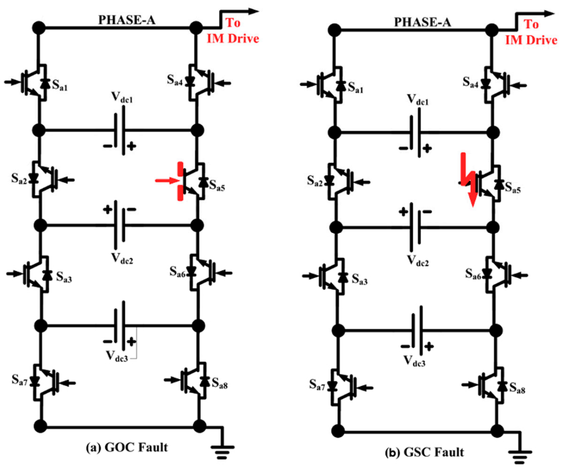
The open-circuit (OC) and short-circuit (SC) faults are those most frequently encountered in multilevel inverter structures, occurring in switches and/or gate-drive circuits. These fault events lead to malfunctioning of the drive system due to extreme thermal and electrical stress experienced by nearby elements. The most systematic faults in the proposed RSMLI are gate-open circuit (GOC) faults and gate-short circuit (GSC) faults, depicted in Figure 3. In these configurations the switches Sa7 and Sa8 are in an idle state for a healthy state and are operational in a faulty state. Figure 3a represents a GOC-fault occurring in the phase A related to switch Sa5 of the RSMLI.
During a fault, it is not possible to transfer energy to the induction motor (IM) drive for continuous operation since the path of current flow becomes unbalanced, which impacts the drive speed and torque, therefore degrading its performance. Figure 3b depicts a phase-A GSC fault for the switch Sa5 of the RSMLI by generating a short circuit related to the switch gate-pulse signal. During this fault, there is a possibility of a high unbalanced current to the IM drive, which affects the magnitude of current in the positive region, again degrading the performance of the IM drive. The fault analysis is the same for other types of faults, such as faults on switches and diodes.

2.3. Fault Identification Using a Discrete Wavelet Transform (DWT) Analysis

The wavelet transform (WT) method was developed as a replacement for the short-time Fourier transform (STFT), which uses fixed-width windowing functions. In the WT method, the width of the window is changed as the transform is computed for each spectral component [24,25]. This multiresolution analysis (MRA) allows for the identification of abrupt variations in electrical parameters such as voltage, current and frequency [17]. Wavelets are localized in both the time and frequency domains, while Fourier transforms are only localized in the frequency domain. The STFT overcomes this limitation partly, but the fixed-width windows lead to a tradeoff between time and frequency resolution. WTs offer greater time and frequency localization and are better for distinguishing important signatures from signals that have high-frequency disturbances that are short-lived, and superimposed on low-frequency signals.
A continuous wavelet transform (CWT) of the signal x t is defined in terms of a mother wavelet ψ t . The mother wavelet is able to the translated and dilated discretely, which generates an orthonormal basis ψ i , j t , where i . j are integers for expressing a signal x t . The coefficients of the signal in this basis define the DWT. MRA, also called the fast wavelet transform (FWT), is a computationally efficient method to perform DWT [26]. This DWT–MRA analysis decomposes the original signal into low- and high-frequency components termed approximations and details, respectively, with divergent scales/levels of resolution. At every level, the approximations are acquired by a convolution signal with a low-pass filter and the details are obtained by the convolution of the signal with a high-pass filter, followed by a dyadic decimation process in both cases.
The procedure begins with evaluating the discrete form of the signal x n , which has a length N passed through digital low-pass and high-pass filters, g n and h n . The outcomes from a low-pass filter are the N approximation coefficients a 1 n , while the high-pass filter produces the detail coefficients d 1 n ; this is the first level of the MRA [27,28,29]. These coefficients are employed as the inputs for a second set of wavelet filters, with sampling by dual functionality. The filters in this level of resolution produce approximation/detail coefficients each of length N/2. This decomposition process is repeatedly applied up to the highest-level L (Figure 4), which enhances the resolution in terms of frequency of the discrete signal. A level 9 wavelet decomposition was utilized in this paper, with the l-th level defined by
a l n   = k = 0 N / 2 l 1 1 g k a l 1 2 n k ,                 d l n   = k = 0 N / 2 l 1 1 h k a l 1 2 n k
A level of 9 ensures that there is sufficient information to form reliable statistics of the coefficients in the presence of noise, while not leading to excessive computational costs. The Haar mother wavelet was selected based on the correlation coefficient value. It is worth mentioning that the computational costs of FWT-MRA is O(N) compared to O (N log2(N)) for the FFT.
In general, the fault in the MIMD system is identified by the gradient of the line current. This is not suitable, however, for dynamic conditions. For these cases, a wavelet-based feature extraction methodology (FEXM) [28] can be used effectively for detecting faults using a decomposition feature rate ( D f r ). The D f r value is determined from a FEXM on the line currents for both healthy and faulty states by first performing a DWT analysis to obtain high-frequency information on the currents in the form of the detail coefficients d l n . Several signatures are then calculated, such as the mean d l ¯ = 1 N / 2 l 1 1 n d l n , median, standard deviation σ d l = 1 N / 2 l 1 2 n d l n d l ¯ 2 and median absolute deviation (Mad), which is the median of d l ¯ d l n , of these coefficients, where d i ,   i = 1 , , L , denotes the decomposition level. From the standard deviations at different levels of decomposition, the D f r is obtained as follows.
D f r = σ d 2   +   σ d 3   + + σ d L 1 L 2 σ h ¯
In which σ h ¯ = L 2 1 i = 2 L 1 σ d i under healthy conditions. The standard deviations of the wavelets coefficients have been used extensively for fault detection in various electrical and mechanical systems [30,31,32]. It can often be the case that the standard deviations for the lowest and highest-level features do not vary significantly from the healthy values [31]. Thus, the summation in (5) discards these values.
Faults can be identified by observing the value of D f r under both healthy and faulty conditions. If D f r is less than a certain threshold value (the value at the healthy condition within a tolerance determined from a prior analysis), then a fault is identified. Nevertheless, D f r is unable to classify the type of fault, so further analysis is required. The average Mad values of the d 2 to d 8 detail coefficients under healthy and different faulty conditions at the different decomposition levels is used to classify the type of fault. These average Mad values in each phase are compared with a threshold value obtained from a prior analysis under faulty and healthy conditions to clearly classify the fault type. If Mad is lower than a threshold, any fault is labelled an OC fault, and it is otherwise classified as a SC fault.

2.4. Fault-Reconfiguration Technique Using Auxiliary Switching Cells

The novel reconfiguration technique of the proposed 5-level symmetrical RSMLI structure in this article is based on a fault reconfiguration technique using back-to-back switches in [30,31,32,33]. It requires only eight IGBT switches in the overall configuration; three equal DC sources (Vdc1 = Vdc2 = Vdc3), powered by a front-end rectifier followed by a DC-link capacitor. The additional auxiliary switching cells Sa7 and Sa8 are incorporated under faulty conditions and are otherwise turned off. For example, if Sa5 in the module fails due to any type of fault then antiparallel thyristors across the switches are activated to continue operation with auxiliary switches. Therefore, when a fault occurs in any switch of the upper and/or lower module, the proposed fault identification scheme activates the auxiliary switch cell through a control unit. During a fault occurrence, the additional fault-tolerance switch Sda is turned off and the corresponding five staircase voltage levels are attained. The switch Sda is nonconducting under faulty conditions due to the energy provided by the auxiliary cells. Figure 5 shows a schematic of the proposed reconfiguration technique under faulty conditions. It is noted that the input DC voltage undergoes a transformation to an AC staircase voltage with proper switching sequences, as shown in Table 2. The corresponding 5-level voltages are Vdc, 2 Vdc, 0 Vdc, −Vdc, and −2 Vdc.
The response of the multilevel inverter can be analyzed using DWT-FEXM signatures under healthy and faulty conditions based on the D f r and the Mad value. The average Mad for each phase is compared with threshold values to classify the fault type. After identification of the fault type, the faulty switch is turned off by using the thyristors, activating the auxiliary switching cell in the respective phase. Furthermore, if the D f r value is less than the threshold value after activation of the auxiliary switch, the process is continued until no fault is detected in the relevant phase of the RSMLI system, the flow-chart of the proposed fault reconfiguration technique is illustrated in Figure 6.

3. Results

3.1. Simulation Results

The RSMLI system is typically operated by an AC source in single phase with an AC-DC front end and a DC-DC converter for constant DC-link voltages to drive the multilevel inverter. In this context, a commanding signal is used to construct the GOC and GSC faults in a RSMLI system; it is set as “0” for OC faults and “1” for SC faults. The DWT–MRA analysis was performed with the MATLAB/Simulink tool. The analysis identifies the faulty switch and faulty phase by measuring the median, mean, standard deviation, and other features of the DWT coefficients using a FEXM. The operating specifications of the proposed RSMLI system are presented in Table 3.

3.1.1. Case A: Evaluation for a Healthy State

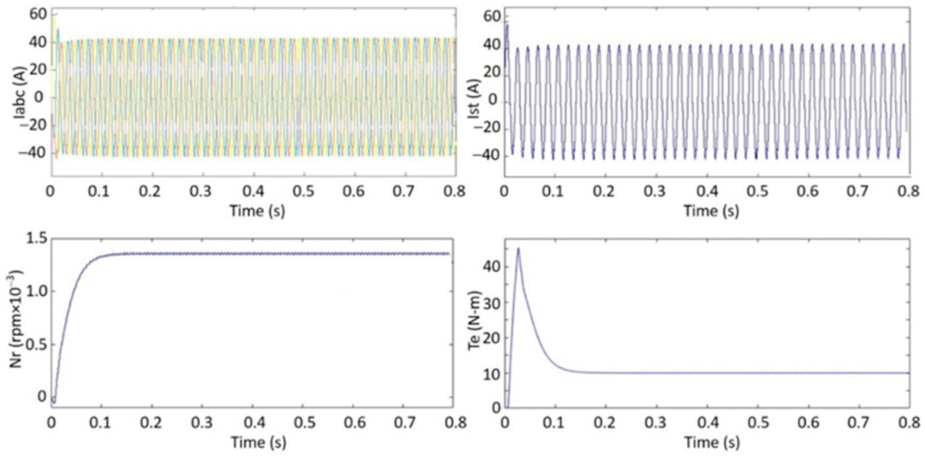
Figure 7 shows the line currents, the stator current, the rotor speed, and the electromagnetic torque under healthy conditions. The line currents (ILabc) are constant at 43.1 A and with a phase displacement of 120°. The stator current (Isa) is maintained sinusoidal with a value of 58 A at the start and 43.1 A under steady-state. The induction motor speed (Nr) reaches a steady-state plateau at 1360 rpm within 0.1 s. The electromagnetic torque (Te) of the induction motor rises to around 45 N-m before settling on the rated mechanical torque at steady-state.

3.1.2. Case B: Performance during GOC Fault and Fault Reconfiguration States

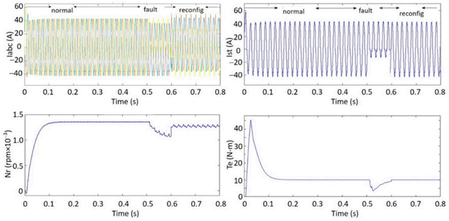
The motor drive performance during reconfiguration was evaluated during a GOC fault and is shown in Figure 8. The GOC fault occurs at t = 0.5 s by opening the gate-pulse of switch Sa5. To compensate the GOC fault, the reconfiguration technique is initiated at t = 0.6 s by activating the switches of the auxiliary switching cell. By virtue of the open-fault, switch Sa5 is considered a gate-pulse failure affecting certain characteristics of the multilevel inverter and induction motor drive. Under prefault conditions before t = 0.5 s, ILabc remains constant at 43.1 A with a phase displacement of 120°, Nr is maintained constant at 1360 rpm and Te is around 10 N-m.
In the period 0.5 s < t < 0.6 s when the fault occurs, the line current of the faulty phase decreases and is unbalanced at 12 A in the negative half-cycle. The rotor speed (Nr) fluctuates and reduces to 1050 rpm, while the electromagnetic torque fluctuates and decreases to 3.5 N-m. During fault reconfiguration, initiated at t = 0.6 s, the line current of the faulty phase recovers to a value of almost 41A and a phase displacement of 120°. The rotor speed (Nr) adopts a constant value of 1360 rpm and the electromagnetic torque (Te) of the induction motor returns to almost 10 N-m.

3.1.3. Case C: Performance during GSC Fault and Fault Reconfiguration States

Under GSC fault conditions, the performance is shown in Figure 9. The fault begins at 0.5 s by the misfiring of the gate-pulse by the addition of the step response to the switching pattern of Sa5. The fault reconfiguration technique is initiated at t = 0.6 s. The prefault conditions before t = 0.5 s are as in cases A and B.
During the fault 0.5 s < t < 0.6 s, the line current of the faulty phase decreases and becomes unbalanced at 27.5 A in the positive half-cycle, while in the other phases there is a small decrease. Nr fluctuates and reduces to 1230 rpm, while Te fluctuates and decreases to 6 N-m, returning to the rated torque within 0.15 s. The maximum fault detection time is 50% of the switching period, while detection is accurate, fast and straightforward. After fault reconfiguration the line current of the faulty phase is maintained as balanced with a value of 41 A and a 120° phase displacement. Nr is maintained at 1360 rpm and Te is nearly 10 N-m.
Following DWT–MRA on the line currents, the FEXM signatures of the detail coefficients under healthy, GOC/GSC fault, and fault reconfiguration conditions are provided in Table 4, with respect to the level of decomposition. Included are the mean, median, standard deviation and Mad. The DAQ-9227 current acquisition card measures the values for a specified number of levels directly from a hardware-interaction system. The data are exported to an Excel sheet and then imported to a mat-file program, which generates the respective wave-shape signatures.
Under healthy conditions, the maximum mean takes on a small negative value of −0.93 at level d 4 . The maximum median is also slightly negative, −3.82 at level d 4 . The highest value standard deviation occurs at d 3 (30.18). The maximum Mad is 30.73, occurring at both d 3 and d 9 . Table 4 shows the signatures related to the GOC fault. The maximums in the mean, median, and standard deviation are obtained at level d 7 , taking values 12.06, 0.75 and 19.43, respectively. The maximum value of Mad is 11.82, at level d 7 . For a GSC fault, the maximum mean and median are negative with values of −10.19 and −13.81 at level d 6 . The maximum standard deviation is 24.65 at level d 9 , while the maximum value of Mad is 22.08, at level d 2 .
Under GOC fault reconfiguration conditions the highest mean and median are 4.88 and 10.25 (level d 5 ) . The maximum in the standard deviation is 28.26, for level d 4 , while the highest Mad is 25.21 attained at level d 8 . The maximums in the mean, median and standard deviation under GSC fault reconfiguration conditions are −5.41, −10.7, attained at levels d 7 and d 9 , while the maximum standard deviation is 27.87, at level d 8 . The highest value of Mad is 24.97, attained at level d 5 . It can be seen that the statistical signatures in Table 4 have variations between states (healthy, faulty, reconfiguration conditions) that can be reliably used for fault analysis, and that the values of the signatures are close to constant from decomposition level to decomposition level. Table 5 shows that the presence of a fault and the type of the fault in the system are reliably identified by D f r and the average Mad.
In Table 5, Equation (5) is used to calculate the D f r values for the different states (healthy, faulty, reconfigured) from the d2 to d8 standard deviations in Table 4. The D f r threshold value is taken as 0.9 for identifying the fault. Similarly, the average Mad values for the different states are calculated from the d2 to d8 Mad values in Table 4. The Mad threshold value for classifying the fault is taken to be 16.46 (midway between the values for the two fault types).
Table 6 compares the drawbacks of the proposed method as well as existing methods. The faulty phase leg isolation method [34] will operate only with two phases under faulty conditions, which results in unbalanced per phase conditions and a reduced peak value. The method of isolating a faulty device using fuses [35] has the drawback of requiring additional components in addition to a complex control strategy and the extra stress placed on the remaining healthy devices. In the method of isolating a faulty cell [36], healthy devices undergoing reconfiguration conditions will experience a higher voltage stress. Moreover, this method cannot be applied to different MLIs. The Active Neutral-Point-Clamped (ANPC) fault-tolerant inverter [37] has many drawbacks, but the main drawback is that it can only be applied to a three-level condition.
Compared to the existing methods, the proposed method requires the most add-on components, namely for the inverter considered, which requires additional thyristors. Although the additional cost will be higher with the proposed method, the lack of other disadvantages suggest it is an attractive option, especially for applications requiring high reliability and near-normal operation.

3.2. Experimental Results

To validate the RSMLI topology and reconfiguration, we conducted experiments by interfacing with MATLAB/Simulink (Figure 10). A total of six Si4850BDY TrenchFET Gen IV power MOSFETs were employed. In this setup, the drain-to-source voltage was set to 80 V and the gate-to-source voltage was set to ±20 V, having a dissipated power of 4.5 W at 25 °C. A CMOS 8-bit microcomputer possessing 4 K bytes of flash-programmable memory was employed for the design of a dSPACE DS1103 digital controller in real time. The PWM signals were generated using the dSPACE under different strategies. The required offline simulations of the gate signal generation blocks for the proposed symmetrical RSMLI using the sinusoidal PWM technique were performed with the help of SIMULINK. The SIMULINK model was compiled before being executed in real time on the dSPACE system. A “build” function in SIMULINK converts the SIMULINK model into C code, which forms the source for the real-time dSPACE system interface. The switching pulses are obtained from the input and output ports of the dSPACE system; they are sent to pulse amplifiers before application to the gates of the power MOSFETs.
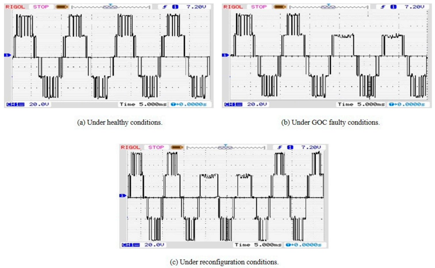
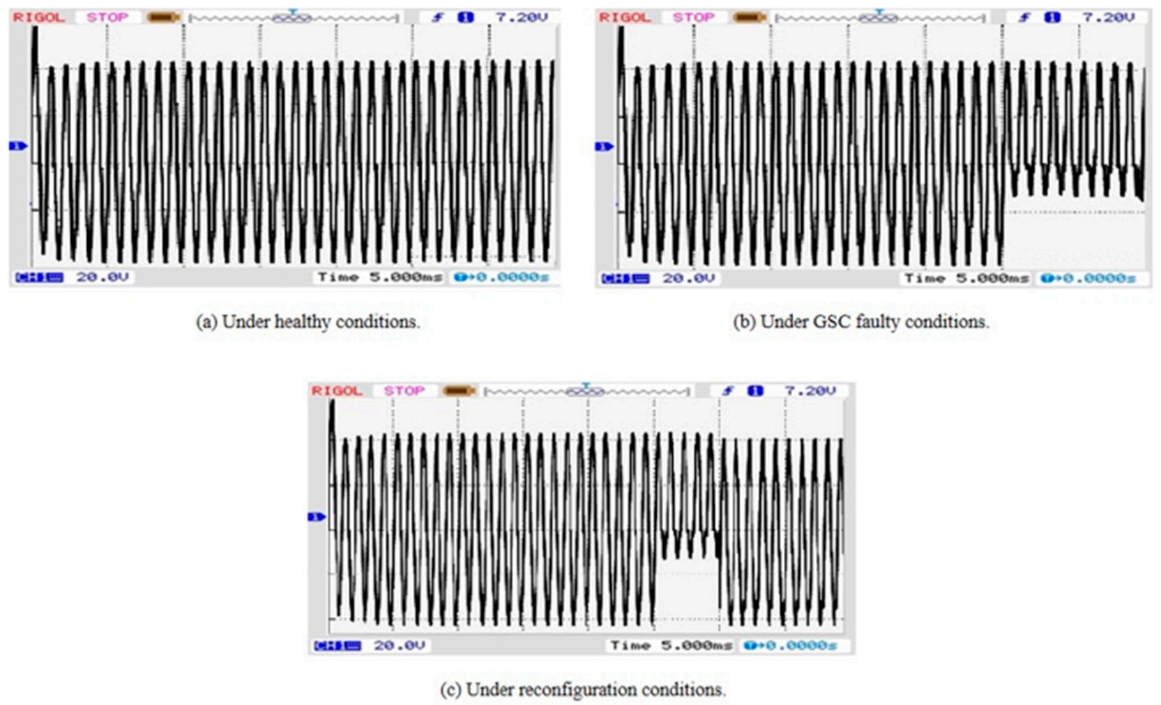
The output voltages for the healthy, faulty and reconfiguration states are shown in Figure 11, Figure 12, Figure 13 and Figure 14, respectively. The staircase 5-level output voltages were generated by activating the relevant switches in the RSMI topology under the control of a frequency-based voltage pulse method. To investigate faulty conditions, an open-switch fault was initiated for switch Sa5 by the opening of its gate pulse. When the fault is initiated in Sa5, Figure 11b shows that the highest voltage level is missed.
After initiating the proposed reconfiguration method, the voltage is reconfigured to the original value as shown in Figure 11c. A short-circuit fault is initiated for Sa5 by the mis-firing of the gate pulse. Switch Sa5 then constitutes a malfunction of the gate-pulse, which decreases the line current (Figure 12b). The healthy and reconfigured current waveforms are depicted in Figure 12a,c, respectively. When the proposed reconfiguration method is initiated, it successfully reconfigures the failed RSMLI in a fraction of a fundamental cycle.
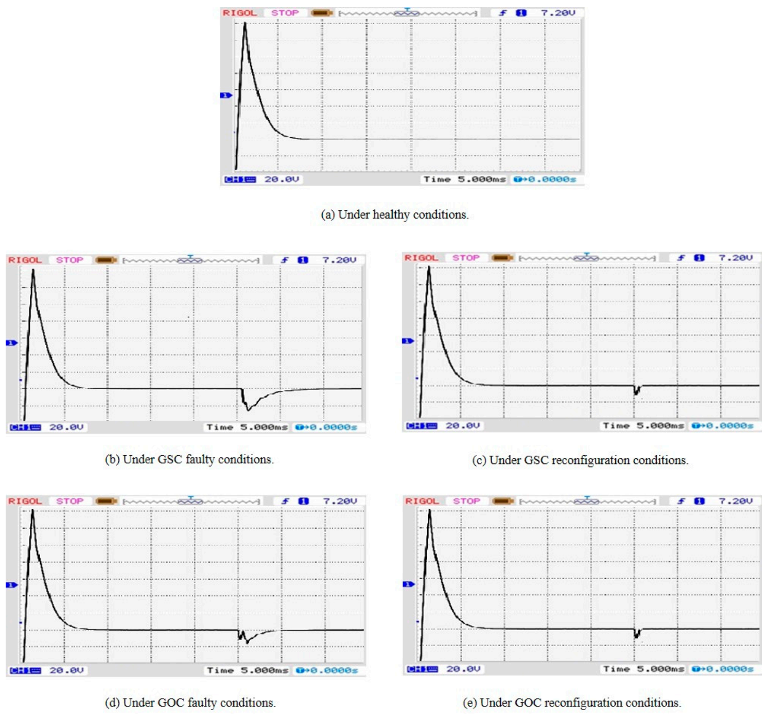
Under prefault conditions, the induction motor rotor speed and torque are maintained at constant values to meet the load requirement, as shown in Figure 13a and Figure 14a. When the GOC and GSC faults are introduced, the values fluctuate, as can be seen in Figure 13b,d and Figure 14b,d, respectively. After the reconfiguration method is implemented, they regain their healthy-condition values, as shown in Figure 13c,e and Figure 14c,e, respectively.

4. Conclusions

The main aim of this paper was to introduce a novel fault reconfiguration technique by utilizing auxiliary switching cells to mitigate open and short circuit faults in a proposed 5-level RSMLI topology which is used in a MIMD system. The DWT–MRA methodology leads to accurate results for the analysis of faults in MIMD systems. It provides a simple but reliable fault analysis based on several signatures by using a FEXM, which identifies and classifies the fault types using prior information. Based on these signatures, a fault reconfiguration technique is initiated by switching the auxiliary switch cells with a reconfiguration switching state. The measured values of the decomposition feature rate D f r and averaged mean absolute deviation Mad are 0.9250 and 27.76 during the fault reconfiguration, which are approximately equal to the healthy condition values of 1 and 30.27, respectively, which underlines the effectiveness of the proposed system. The technique is applicable to any MIMD system with a high number of voltage levels and can mitigate both open and short circuit faults. In our experiments we validated the effectiveness of the approach.

Author Contributions

Conceptualization, A.S.V., M.R.M., A.A.S.; methodology, A.S.V., A.A.S., M.R.M.; software, A.S.V.; validation, A.S.V.; writing—original draft preparation, A.S.V., A.A.S., M.R.M.; writing—review and editing, A.S.V., A.A.S., M.R.M., P.L., C.P.S.; supervision, M.R.M.; project administration, M.R.M.; funding acquisition, A.A.S., M.R.M. All authors have read and agreed to the published version of the manuscript.

Funding

This work was partially supported by the National Key Research development Program of China (Grant No. 2017YFB0701700). This project was supported by University Malaysia Pahang (UMP) and A.S. Veerendra is working under UMP’s Doctoral Research Scheme (DRS).

Conflicts of Interest

The authors declare no conflict of interest.

References

  1. Ojha, A.; Chaturvedi, P.; Mittal, A.; Jain, S. Carrier Based Common Mode Voltage Reduction Techniques in Neutral Point Clamped Inverter Based AC-DC-AC Drive System. J. Power Electron. 2016, 16, 142–152. [Google Scholar] [CrossRef] [Green Version]
  2. Mahato, B.; Raushan, R.; Jana, K.C. Modulation and control of multilevel inverter for an open-end winding induction motor with constant voltage levels and harmonics. IET Power Electron. 2017, 10, 71–79. [Google Scholar] [CrossRef]
  3. Sankala, A.; Korhonen, J.; Ström, J.; Luukko, J.; Silventoinen, P.; Komulainen, R.; Sarén, H.; Södö, N.; Isaksson, D. Modular double-cascade converter for high-power medium-voltage drives. IET Power Electron. 2015, 8, 1661–1669. [Google Scholar] [CrossRef]
  4. Chandran, B.P.; Selvakumar, A.I.; Mathew, F.M. Integrating multilevel converters application on renewable energy sources—A survey. J. Renew. Sustain. Energy 2018, 10, 065502. [Google Scholar] [CrossRef]
  5. Porru, M.; Serpi, A.; Marongiu, I.; Damiano, A. Suppression of DC-link voltage unbalance in three-level neutral-point clamped converters. J. Frankl. Inst. 2018, 355, 728–752. [Google Scholar] [CrossRef]
  6. Abdullah, R.; Rahim, N.A.; Raihan, S.R.S.; Ahmad, A.Z. Five-Level Diode-Clamped Inverter with Three-Level Boost Converter. IEEE Trans. Ind. Electron. 2014, 61, 5155–5163. [Google Scholar] [CrossRef] [Green Version]
  7. Raj, M.M.P.; Sundaram, S.S.M. Cascaded H-Bridge Five-Level Inverter for Grid-Connected Photovoltaic System Using Proportional–Integral Controller. Meas. Control. 2016, 49, 33–41. [Google Scholar] [CrossRef] [Green Version]
  8. Matos, D.M.B.; Estima, J.O.; Cardoso, A.J.M. Fault Analysis of Three-Level NPC Inverters in Synchronous Reluctance Motor Drives. In Privacy and Identity Management. Facing up to Next Steps; Springer: Berlin, Germany, 2016; Volume 470, pp. 206–216. [Google Scholar]
  9. Veerendra, A.S.; Mohamed, M.R.; Sulaiman, M.H.; Sudhakar, K.; Peddakapu, K. Modelling and simulation of dual sourced front-end converter for hybrid electric vehicles. Int. J. Ambient. Energy 2020, 1–8. [Google Scholar] [CrossRef]
  10. D′Aversa, A.; Hughes, B.; Patel, S. Challenges and Solutions of Protecting Variable Speed Drive Motors. In Proceedings of the 66th Annual Conference on Protective Relay Engineers, College Station, TX, USA, 8–11 April 2013; pp. 250–256. [Google Scholar]
  11. Lezana, P.; Pou, J.; Meynard, T.A.; Rodriguez, J.; Ceballos, S.; Richardeau, F. Survey on Fault Operation on Multilevel Inverters. IEEE Trans. Ind. Electron. 2010, 57, 2207–2218. [Google Scholar] [CrossRef] [Green Version]
  12. Priya, Y.K.; Kumar, M.V. Analysis of various switch faults of the Three level Neutral point clamped inverter feeding induction motor drive. In Proceedings of the 2016 2nd International Conference on Advances in Electrical, Electronics, Information, Communication and Bio-Informatics (AEEICB), Chennai, India, 27–28 February 2016; pp. 580–586. [Google Scholar]
  13. Trabelsi, M.; Boussak, M.; Gossa, M. Multiple IGBTs open circuit faults diagnosis in voltage source inverter fed induction motor using modified slope method. In Proceedings of the The XIX International Conference on Electrical Machines—ICEM 2010, Rome, Italy, 6–8 September 2010; pp. 1–6. [Google Scholar]
  14. Estima, J.O.; Cardoso, A.J.M. A New Algorithm for Real-Time Multiple Open-Circuit Fault Diagnosis in Voltage-Fed PWM Motor Drives by the Reference Current Errors. IEEE Trans. Ind. Electron. 2013, 60, 3496–3505. [Google Scholar] [CrossRef]
  15. Romero-Troncoso, R.D.J. Multirate Signal Processing to Improve FFT-Based Analysis for Detecting Faults in Induction Motors. IEEE Trans. Ind. Inf. 2016, 13, 1291–1300. [Google Scholar] [CrossRef]
  16. Moussa, M.A.; Boucherma, M.; Khezzar, A. A Detection Method for Induction Motor Bar Fault Using Sidelobes Leakage Phenomenon of the Sliding Discrete Fourier Transform. IEEE Trans. Power Electron. 2016, 32, 5560–5572. [Google Scholar] [CrossRef]
  17. Corral-Hernández, J.A.; Antonino-Daviu, J.A. Influence of the Start-up System in the Diagnosis of Faults in the Rotor of Induction Motors using the Discrete Wavelet Transform. Procedia Comput. Sci. 2016, 83, 807–815. [Google Scholar] [CrossRef] [Green Version]
  18. Moosavi, S.; Kazemi, A.; Akbari, H. A comparison of various open-circuit fault detection methods in the IGBT-based DC/AC inverter used in electric vehicle. Eng. Fail. Anal. 2019, 96, 223–235. [Google Scholar] [CrossRef]
  19. Wu, F.; Hao, Y.; Zhao, J.; Liu, Y. Current similarity based open-circuit fault diagnosis for induction motor drives with discrete wavelet transform. Microelectron. Reliab. 2017, 75, 309–316. [Google Scholar] [CrossRef]
  20. Cheon, J.-M.; Kim, C.-K.; Lee, J.-M.; Kim, S.-J.; Kwon, S. A New Fault Detectior for Three-Phase Half-Wave Converter Using Wavelet Transform. IFAC Proc. Vol. 2003, 36, 945–950. [Google Scholar] [CrossRef]
  21. Balamurugan, C.R.; Natarajan, S.; Bensraj, R.; Shanthi, B. A Review on Modulation Strategies of Multi Level Inverter. Indones. J. Electr. Eng. Comput. Sci. 2016, 3, 681. [Google Scholar] [CrossRef]
  22. Xiao, M.; Xu, Q.; Ouyang, H. An Improved Modulation Strategy Combining Phase Shifted PWM and Phase Disposition PWM for Cascaded H-Bridge Inverters. Energies 2017, 10, 1327. [Google Scholar] [CrossRef] [Green Version]
  23. Chavali, P.S.; Rao, P.V.R.; Vani, M.U. A Novel Multilevel Inverter with Reduced Number of Switches Using Simplified PWM Technique. J. Inst. Eng. Ser. B 2020, 101, 203–216. [Google Scholar] [CrossRef]
  24. Ahmed, I.; Borghate, V.B. Simplified space vector modulation technique for seven-level cascaded H-bridge inverter. IET Power Electron. 2014, 7, 604–613. [Google Scholar] [CrossRef]
  25. Gaeid, K.S.; Maher, R.A.; Lazim, A.J. Multilevel Inverter Fault-Tolerant Control with Wavelet Index in Induction Motor. J. Electr. Eng. Technol. 2019, 14, 1179–1191. [Google Scholar] [CrossRef]
  26. Bialasiewicz, J.T.; Gonzalez, D.; Balcells, J.; Gago, J. Wavelet-Based Approach to Evaluation of Signal Integrity. IEEE Trans. Ind. Electron. 2012, 60, 4590–4598. [Google Scholar] [CrossRef] [Green Version]
  27. Keswani, R.A.; Suryawanshi, H.M.; Ballal, M.S. Multi-resolution analysis for converter switch faults identification. IET Power Electron. 2015, 8, 783–792. [Google Scholar] [CrossRef]
  28. Ananthan, S.N.; Padmanabhan, R.; Meyur, R.; Mallikarjuna, B.; Reddy, M.J.B.; Mohanta, D.K. Real-time fault analysis of transmission lines using wavelet multi-resolution analysis based frequency-domain approach. IET Sci. Meas. Technol. 2016, 10, 693–703. [Google Scholar] [CrossRef]
  29. Jung, S.-M.; Park, J.-S.; Kim, H.-W.; Cho, K.-Y.; Youn, M.-J. An MRAS-Based Diagnosis of Open-Circuit Fault in PWM Voltage-Source Inverters for PM Synchronous Motor Drive Systems. IEEE Trans. Power Electron. 2012, 28, 2514–2526. [Google Scholar] [CrossRef]
  30. Kompella, K.D.; Mannam, V.G.R.; Rayapudi, S.R. DWT based bearing fault detection in induction motor using noise cancellation. J. Electr. Syst. Inf. Technol. 2016, 3, 411–427. [Google Scholar] [CrossRef] [Green Version]
  31. Kim, I.-S. On-line fault detection algorithm of a photovoltaic system using wavelet transform. Sol. Energy 2016, 126, 137–145. [Google Scholar] [CrossRef]
  32. Lopez-Hernandez, M.; Rangel-Magdaleno, J.; Peregrina-Barreto, H.; Ramirez-Cortes, J. Detection of broken bars on induction motors using MODWT. In Proceedings of the 2018 IEEE International Instrumentation and Measurement Technology Conference (I2MTC), Houston, TX, USA, 14–17 May 2018; pp. 1–5. [Google Scholar]
  33. Chen, W.; Bazzi, A.M. Logic-Based Methods for Intelligent Fault Diagnosis and Recovery in Power Electronics. IEEE Trans. Power Electron. 2017, 32, 5573–5589. [Google Scholar] [CrossRef]
  34. AbdelGhani, A.B.-B.; Ben-Abdelghani, H.; Richardeau, F.; Blaquiere, J.-M.; Mosser, F.; Slama-Belkhodja, I. Versatile Three-Level FC-NPC Converter with High Fault-Tolerance Capabilities: Switch Fault Detection and Isolation and Safe Postfault Operation. IEEE Trans. Ind. Electron. 2017, 64, 6453–6464. [Google Scholar] [CrossRef]
  35. Chen, W.; Hotchkiss, E.; Mademlis, C.; Bazzi, A.M. Integrated fault diagnosis and recovery in NPC multi-level inverters. In Proceedings of the 2017 IEEE 11th International Symposium on Diagnostics for Electrical Machines, Power Electronics and Drives (SDEMPED), Tinos, Greece, 29 August–1 September 2017; pp. 415–421. [Google Scholar] [CrossRef]
  36. Chen, W.; Hotchkiss, E.; Bazzi, A. Reconfiguration of NPC multi-level inverters to mitigate short circuit faults using back-to-back switches. CPSS Trans. Power Electron. Appl. 2018, 3, 46–55. [Google Scholar] [CrossRef]
  37. Shen, Y.; Miao, B.; Wu, D.; Ibrahim, K.A. Fault-Tolerant Control Strategy for Neutral-Point-Clamped Three-Level Inverter. J. Control. Sci. Eng. 2018, 2018, 1–9. [Google Scholar] [CrossRef] [Green Version]
Figure 1. Schematic of the proposed three-phase 5-level symmetric RSMLI fed induction motor drive under healthy conditions.
Electronics 10 01023 g001
Figure 2. Simplified switching pattern. * C–conduction, NC—nonconduction.
Electronics 10 01023 g002
Figure 3. (a) Gate-open and (b) gate-short circuit fault states.
Electronics 10 01023 g003
Figure 4. Decomposition process for the discrete signal in DWT.
Electronics 10 01023 g004
Figure 5. Schematic of the proposed fault-reconfiguration technique in a three-phase 5-level symmetric RSMLI fed induction motor drive system under faulty conditions.
Electronics 10 01023 g005
Figure 6. Flow chart of the fault reconfiguration technique.
Electronics 10 01023 g006
Figure 7. Simulation results under healthy conditions.
Electronics 10 01023 g007
Figure 8. Simulation results during a GOC fault and the fault reconfiguration technique.
Electronics 10 01023 g008
Figure 9. Simulation results during GSC fault and fault reconfiguration.
Electronics 10 01023 g009
Figure 10. Hardware prototype model.
Electronics 10 01023 g010
Figure 11. 5-Level output voltage under healthy, GOC faulty and reconfiguration conditions.
Electronics 10 01023 g011
Figure 12. 5-Level output current under healthy, GSC faulty and reconfiguration conditions.
Electronics 10 01023 g012
Figure 13. Rotor speed of the induction motor for healthy conditions, and faulty and reconfiguration conditions.
Electronics 10 01023 g013
Figure 14. Electromagnetic torque of the induction motor under healthy, faulty and reconfiguration conditions.
Electronics 10 01023 g014
Table 1. Sequences of switching for the 5-level symmetric RSMLI structure under healthy conditions.
Outcome VoltagesSa1Sa2Sa3Sa4Sa5Sa6Sa7Sa8
VdcCNCNCNCCC--
2 VdcCNCCNCCNC--
−VdcNCCCCNCNC--
−2 VdcNCCNCCNCC--
0 VdcCCCNCNCNC--
Table 2. Novel reconfiguration switching sequences of proposed 5-level symmetric RSMLI structure in faulty conditions.
Outcome VoltagesSa1Sa2Sa3Sa4Sa5Sa6Sa7Sa8
VdcNCCCC-NCCNC
2 VdcNCCNCC-CNCC
−VdcCCCNC-NCNCC
−2 VdcNCNCCC-NCNCC
0 VdcCCCNC-NCCNC
C–conduction, NC–nonconduction.
Table 3. System specifications.
ParametersValues
AC SourceVsa = 230 V, F = 50 Hz
InductorsLb1 = Lb2 = Lb3 = 1.2 mH
DC-Link CapacitorCdc = 690 µF,
Vdc1 = Vdc2 = Vdc3 = 200 V
Switching FrequencyFs = 3050 Hz
Induction MotorVo = 400 V, Pm = 10 HP, Tm = 10 N-m
Table 4. Signatures measured under different conditions with respect to the level of decomposition.
Level of Decomposition
d 1 d 2 d 3 d 4 d 5 d 6 d 7 d 8 d 9
Under healthy conditions
Mean−0.46−0.52−0.29−0.93−0.53−0.82−0.38−0.29−0.33
Median−3.59−3.36−2.72−3.82−3.12−3.59−3.12−3.13−2.72
Standard Deviation30.0630.1130.1829.9630.1229.9730.1530.1430.15
Median Absolute Deviation29.9730.1530.7329.7430.3729.9730.4530.4530.73
Under GOC faulty conditions
Mean11.8411.4311.6411.7411.5611.3512.0611.7411.35
Median0.490.040.050.050.040.040.750.050.04
Standard Deviation19.3819.4219.3619.2619.3319.3219.4319.2619.32
Median Absolute Deviation11.6311.1211.1710.9811.1210.9411.8210.9810.94
Under GSC faulty conditions
Mean−9.17−8.83−9.01−10.09−9.62−10.19−8.91−9.48−9.19
Median−13.4−12.95−12.95−13.69−13.57−13.81−13.11−13.52−13.28
Standard Deviation24.4424.6124.6124.6124.5124.5824.4224.5124.65
Median Absolute Deviation21.7122.0822.0721.6221.6121.4521.7821.6421.92
Under GOC fault reconfiguration conditions
Mean4.854.614.644.544.884.564.714.574.65
Median10.2310.1210.079.9210.259.9310.19.8310.01
Standard Deviation28.1928.1528.2228.2628.1528.2128.1628.1128.13
Median Absolute Deviation24.8725.0224.9925.1624.8125.1224.9525.2125.02
Under GSC fault reconfiguration conditions
Mean−5.12−5.22−5.21−5.31−5.13−5.25−5.41−5.22−5.41
Median−10.1−10.4−10.5−10.6−10.1−10.5−10.7−10.4−10.7
Standard Deviation27.7727.7927.8427.8127.8227.8527.7927.8727.79
Median Absolute Deviation24.9324.8024.7524.6424.9724.7524.6424.8024.64
Table 5. Measured D f r values under healthy, faulty and reconfiguration conditions.
HealthyUnder Fault ConditionUnder Fault Reconfiguration
GOCGSCGOCGSC
D f r   10.64270.81590.93640.9250
Average Mad ( d 2 : d 8 )30.2711.1621.7525.0327.76
Table 6. Comparison of the proposed method with existing methods.
Faulty Phase Leg Isolation MethodIsolating a Faulty Device Using FusesFaulty Cell Isolation
Method
ANPC Fault-Tolerant InverterProposed Method
Extra Stress on Devices
Unbalanced Per-phase Condition
Reduced Peak Value
Excessive Complexity of Control
Excessive Add-on Components
Not Applicable to
Different Inverters
Not Applicable to Different Levels
Publisher’s Note: MDPI stays neutral with regard to jurisdictional claims in published maps and institutional affiliations.