Article

Study and Optimization of Transmission Characteristics of the Magnetically Coupled Resonant Wireless Transmission System

1
Guangxi Key Laboratory of Hybrid Computation and IC Design Analysis, Guangxi University for Nationalities, Nanning 530006, China
2
College of Electronic Information, Guangxi University for Nationalities, Nanning 530006, China
*
Authors to whom correspondence should be addressed.
Electronics 2022, 11(13), 1940; https://doi.org/10.3390/electronics11131940
Submission received: 21 May 2022 / Revised: 19 June 2022 / Accepted: 20 June 2022 / Published: 21 June 2022
(This article belongs to the Section Microwave and Wireless Communications)

Abstract

:
The topology and parameter characteristics of the wireless energy transmission system are the main factors affecting the system’s performance. A series–parallel–series–parallel (spsp) topology for magnetically coupled wireless energy transmission is proposed to address the problems of low efficiency and low output power when transmitting electrical energy in the conventional magnetically coupled topology. The spsp topology is compared with the conventional topology based on circuit theory, and the two structures are modeled, characterized, and verified in detail. Simulations and tests are performed for the transmission conditions, an improved Gray Wolf optimization algorithm is proposed, and a physical system is built. Experiments show that the spsp structure is superior near the designed circuit parameters when the network works in a resonant state. The improved Gray Wolf optimization algorithm is then used to find the optimal parameters, and the transmission efficiency reaches 90.53%, which effectively improves the transmission performance of the system. The established physical system utilizes the optimized parameters for coil structure and coil offset experiments, and the average transmission efficiency is 83.75%, with an error of 6.78% calculated by data measurement. The rationality of the proposed structure and the correctness of the simulation parameter design method are verified, and it is hoped that the proposed system and circuit structure in this paper will provide a reference for the design of a magnetically coupled wireless energy transmission system.

1. Introduction

In today’s world, due to atmospheric pollution, global warming, and energy security, various countries emphasize the extraction and use of clean energy to conserve resources and protect the environment. To reduce energy consumption and CO2 emissions, the Chinese government has enacted a series of policies to guide and support the healthy development of new energy vehicles, electrochemical energy storage, and battery material technologies, providing financial subsidies, supplementary promotion, and infrastructure support for the current electric vehicle wireless charging sector.
The most basic charging method for charging electric vehicles is plug-in charging, which is divided into AC slow charging and DC fast charging methods. Plug-in charging connection cables transmit energy, all using a fixed power charging mode, which poses a negative impact on the safe and stable operation of the power grid and forms a superimposed load spike in case of electricity stress. The charging pile connection cables are thick and heavy, with aging and deterioration, cold weather and hardening safety hazards, uneven quality of sockets, and waste of land resources in terms of site occupation. The wireless charging mode does not require charging piles and has a high safety factor and a low level of danger, which is the trend of electric vehicle charging and the potential practical value is becoming more and more prominent.
There are numerous studies on resonant coil structures both nationally and internationally. Kurs et al. (2007) [1] presented a paper on magnetically coupled resonant wireless energy transfer technology, showing a four-coil model with the middle two coils dedicated to generating magnetic field resonance. This technology lit a 60 W light bulb two meters away. Karalis et al. (2008) [2] proposed a theoretical and experimental study of wireless charging coils during the movement of electric vehicles at Oak Ridge National Laboratory in the United States. They developed a wireless charging system with a transmission efficiency of 80%. Liu et al. (2020) [3] proposed a new magnetically coupled resonant wireless power transmission (MCR-WPT) system with good out-of-tune fault tolerance. Liu et al. (2018) [4] proposed a reconfigurable modular magnetically coupled resonant wireless power transfer array system with energy transfer efficiency above 78%. Wang et al. (2021) [5] proposed a near-field wireless power transmission (WPT) system for implantable medical devices, such as pacemakers. Operating at 403 MHz in the Medical Implant Communication Service (MICS) band, the WPT link constitutes an in vitro primary loop as a transmitter and a single-turn implantable loop as a receiver. Lu et al. (2021) [6] proposed a dual-band omnidirectional 3-D WPT system. The power emitted by the transmitter can be received by any receiver operating at 13.56 and 27.12 MHz located at any position. Dual-band 3-D square and circular transmitters are designed and demonstrated. The performance of the WPT system in concrete structures was verified for real-world situations. Cheng et al. (2019) [7] proposed a novel wireless transmission system with relay coils suitable for multiple loads. They used a series–parallel–series (SPS) compensation method for each relay coil unit to verify the effectiveness of the multi-load system. Fu et al. (2018) [8] proposed a 6.78 MHz multi-receiver wireless power transmission system driven by a Class E power amplifier that allows fast voltage regulation with an overall optimal system efficiency of 66.6%. Zhang et al. (2018) [9] presented a novel view of wireless technology, using science, technology, materials, classical application techniques, and new systems to understand better what is happening in life. Zheng et al. (2020) [10] proposed a fuzzy PL composite controller adaptive frequency tracking control method that can obtain higher output power and system efficiency. Peng et al. (2019) [11] proposed a simple T-shaped network inserted in a magnetically coupled resonant system to achieve load independence. Zhao et al. (2021) [12] proposed a four coil circuit model, introduced a genetic algorithm to optimize the solution for transmission efficiency, and performed a simulation to verify it. Yan et al. (2022) [13] proposed that the order of magnitude mismatch between the output power and transmission efficiency of magnetically coupled resonance (MCR) radio energy transmission (WPT) system and the efficiency synchronization optimization strategy needed feature fusion Pareto optimal solution, and proposed the entropy method of power efficiency feature scaling to calculate the weight of feature fusion of Pareto solution set. The synchronization optimization objective function of improving efficiency under an out-of-step state is obtained, and the synchronous improvement of output power and transmission efficiency is realized. Yang et al. (2020) [14] proposed an improved standard artificial bee colony algorithm to improve the frequency splitting phenomenon in the magnetic coupling system. Through calculation and experiments, it is proved that the output power of the system in the over-coupling state can be improved and stabilized on the premise of ensuring transmission efficiency. Zhang et al. (2020) [15] proposed a multi-objective optimization method based on analytic expression and NSGA-II algorithm. This design method does not need repeated finite element simulation calculation, which greatly reduces the calculation time. The optimization results prove the effectiveness of this method. Zhang et al. (2020) [16] proposed the expression of transmission efficiency of a four-coil magnetically coupled resonant radio energy transmission system and analyzed the main factors affecting transmission efficiency. The differential evolution algorithm is used to optimize the influence factors, and the correctness of this method is verified by simulation. Cui et al. (2022) [17] proposed the development history of dynamic wireless power supply systems for electric vehicles, and then combined with the classification of the magnetic coupling mechanism, analyzed the structure types and characteristics of the main research at present, and introduced the key problems and status quo of the main research on magnetic coupling mechanism in detail. Finally, the key issues that need to be studied in the future are discussed. Ni et al. (2020) [18] proposed the conical magnetically coupled resonant coil and compared the power transmission efficiency of the conical resonant coil and the spiral resonant coil. The results show that when the axial spacing is within a certain range, the power transmission efficiency of conical resonant coil is higher. Therefore, the study of magnetically coupled resonant systems is of great practical importance. Zhang et al. (2021) [19] proposed a novel multiple-input multiple-output (MIMO) ICPT system. The effect of cross-coupling of coils on the same side was analyzed, based on which a circuit was designed, a parameter configuration method for resonance compensation was proposed, and finally a single-input, single-output system was constructed. The results show that the co-directional connection of the coils of the E- and UE-shaped magnetic coupling structures has an enhanced effect on the secondary side coupling. Nakamura et al. (2021) [20] proposed an automatic resonance compensation system that uses a circuit capable of electronically controlling the equivalent capacitance to automatically compensate for changes in inductance caused by coil deformation, thereby maintaining resonance. The results show that the system has highly responsive control. Bilandžija et al. (2021) [21] proposed a three-dimensional transmitting coil (TX) with a uniform magnetic field distribution. The proposed coil structure consists of two layers, each with a different number of turns, i.e., with a different current distribution. The optimal layer placement and current distribution were optimized using a genetic algorithm (GA). The measured results agree with the simulation results by more than 95%. Jawad et al. (2021) [22] proposed techniques to address power transfer optimization and improve efficiency. Simulation and experimental results show that the transmission distance improves when the UAV battery load is 100 Ω. The magnetic resonance coupling (MRC) based circuit is demonstrated to be an effective technique to improve the power transfer efficiency for different remote and person-less Internet (IoT) applications, including UAVs for radiation monitoring and smart agriculture. Feng et al. (2021) [23] proposed to implement a parameter-optimized control strategy for the circuit. Finally, through simulations and experiments, it is concluded that the efficiency of the parameter optimization strategy proposed in this study is as high as 91.86% at different power levels, with an increment of approximately 1%, which is of some practical significance. Sato et al. (2022) [24] proposed a novel function for efficient magnetically coupled resonant wireless power transmission while suppressing the magnetic field absorption of metallic foreign bodies. An algorithm is proposed to find the optimal combination of coil input voltage phase and amplitude with coil arrangement using particle swarm optimization (PSO) in terms of magnetic field suppression and transmission efficiency. The results show that the magnetic field suppression effect increases with the number of transmission coils, demonstrating the effectiveness of the proposed algorithm.
The wireless charging method can effectively avoid the disadvantages of the traditional method, so the wireless charging method has become the main way to change the charging method of electric vehicles. The research scheme of magnetically coupled resonant wireless electric vehicle charging is designed for realistic scenarios. The research content of the above literature review mainly investigates a single influencing factor or a single target, without taking into account the variation in system transmission characteristics of multiple factors and targets in realistic situations. In contrast, this paper explores and studies the mechanism of magnetically coupled resonant wireless charging technology, and analyzes the key parameters affecting the transmission system. The key influencing factors are the resonant frequency, coupling coefficient, load resistance, transmission distance, coil wire diameter, coil radius, and other parameters. Additionally, some corresponding optimization methods are proposed to discuss the relationship between the transmission characteristics of the system and the inductance-capacitance of the resonant coil, and the design of the coil at different offset distances to maximize the transmission efficiency. Therefore, it is of great practical importance to study magnetically coupled resonant systems.
In this paper, a new magnetically coupled resonant series–parallel–series–parallel (spsp) topology is firstly proposed, which allows higher output power and transmission efficiency compared to conventional topologies. It is implemented based on circuit theory analysis, where the imaginary part of the parallel network varies less at resonance when the load of the parallel network on the secondary side changes. Under the same parameter conditions, it has superior transmission performance than the conventional sp topology.
This thesis is organized as follows. Firstly, the traditional topology and the new topology are introduced. By comparing them, a mathematical model for the multi-objective optimization of the magnetically coupled mechanism is established with the parameters of resonant frequency, coupling coefficient, load resistance, coil radius, and coil wire diameter as the independent variables and the transmission efficiency as the objective. Then, the mathematical model is solved using the improved grey wolf optimization algorithm, and the optimal parameters are found as design parameters in the optimal solution by analyzing the objective function. Finally, a physical prototype of the prototype was produced and tested to demonstrate the effectiveness of the proposed system. The system is well suited for practical wireless power transmission (WPT) applications with multi-objective parameter optimization.

2. Fundamentals

The actual use of the principle of electromagnetic induction to realize the principle of wireless energy transfer needs to be satisfied: long-range transmission and high-power transmission. Figure 1 shows a typical space-carrying coil with a radius of r , Current is i , a point p of the receiving coil is chosen and the distance between the point p and the x y plane is z . The coordinates of the point p in the spherical coordinate system are ( r , α , θ ) . Without considering the mutual inductance between the coils, the magnetic induction at point p , using Biosavers’ law, is:
B z = u 0 i r 1 4 π 0 2 π z cos θ e x + z sin θ e y + ( r 1 r 2 cos θ ) e z ( z 2 + r 1 2 + r 2 2 2 r 1 r 2 cos θ ) 3 2 d θ
The magnetic induction generated at the point p is only perpendicular to the plane of the in-flow coil, forming an effective magnetic flux b . When b is changed, the coil r 2 generates an induced electric potential, thus doing work on the load resistance, the expression for the effective magnetic flux is:
B z = u 0 i r 1 4 π 0 2 π r 1 r 2 cos θ ( z 2 + r 1 2 + r 2 2 2 r 1 r 2 cos θ ) 3 2 d θ
The magnetic flux in the area enclosed by the coil r 2 is:
ϕ = 0 r 2 B z 2 π r 2 d r 2
The induced electric potential generated by the coil r 2 is:
u = d ϕ d t
Let the excitation current in the coil r 1 be:
i = A sin ( ω t + φ )
According to the above equation, the induced electric potential generated by the coil r 2 is:
u = u 0 A ω cos ( ω t + φ ) 2 0 r 2 0 2 π r 1 2 r 2 r 1 r 2 cos θ ( z 2 + r 1 2 + r 2 2 2 r 1 r 2 cos θ ) 3 2 d θ d r 2 = u 0 A ω cos ( ω t + φ ) r 1 2 r 2 2 2 ( z 2 + r 1 2 + r 2 2 ) 3 2
The above equation shows that the induced electromotive force r 2 is proportional to the resonant frequency of the source and inversely proportional to the square of the distance. Based on the above analysis, the resonant frequency of the source coil should be large enough to generate a large induced electric potential at a certain distance, and according to the law of flutters, the rapid change of magnetic flux will hinder the change of the induced current, so the compensation structure needs to be added to offset the effect of flux change on the induced current.

3. Analysis of Magnetically Coupled Resonant Transmission Structures

In order to increase the induced electric potential of the coil r 2 in the above model, as well as to effectively improve the transmission efficiency of the system, and the transmission power and to achieve good transmission performance even at longer distances, it is necessary to add compensation capacitors to the transmitting and receiving coils so that they work in the resonant This is why it is necessary to add compensation capacitors to the transmitting and receiving coils so that they operate in resonance.
Four conventional compensation structures are currently available: ss structure (series primary-series secondary), sp structure (series primary-parallel secondary), pp structure (parallel primary-parallel secondary), ps (parallel primary-series secondary). As this system utilizes a magnetically coupled resonant structure for wireless charging of electric vehicles, the primary side power supply is a constant voltage source, i.e., this paper only develops detailed modeling, characterization, and verification using electromagnetic coupling theory for the new spsp structure (series–parallel–series–parallel) and the traditional classical structure sp (series–parallel).

3.1. Modelling of SPSP Magnetically Coupled Resonant Structures

The series–parallel–series–parallel (spsp) compensation structure is shown in Figure 2, where U m is the voltage source, the primary resonant transmitting coil is L 0 , the secondary resonant receiving coil is L 1 , M p ( d ) is the mutual inductance of the two coils, I a is the current at the supply, I a 1 is the current at the transmitting coil, I a 2 is the current at the receiving coil and I a L is the current at the load. According to the circuit principle analysis, the KVL equation can be obtained as follows:
U m = I a ( R s + j w L 01 + 1 j w C 01 ) + I a 1 ( j w L 0 ) j w M p I a 2
U m = I a ( R s + j w L 01 + 1 j w C 01 ) + ( I a I a 1 ) ( 1 j w C 0 )
j w M p I a 1 = I a 2 ( j w L 1 + 1 j w C 1 ) + I a L ( j w L 11 + R L )
j w M p I a 1 = I a 2 ( j w L 1 + 1 j w C 1 + 1 j w c 01 ) I a L ( 1 j w c 11 )
According to Kirchhoff’s law and the relation of the matrix, there are:
Z I = U
From I = [ I a I a 1 I a 2 I a L ] T , U = [ U S   U S   0   0 ] T , the impedance expression for this structure is introduced as:
Z a = [ r s + j w L 01 + 1 j w C 01   j w L 0     j w M   0 r s + j w L 01 + 1 j w C 01 + 1 j w C 0 1 j w C 01 0   0 0     j w M   j w L 1 + 1 j w C 1     0 0 j w M   j w L 1 + 1 j w C 1 + 1 j w C 11 1 j w C 11 ]
The output power of the power supply, the output power of the load, the transmission efficiency, the capacitance, and the coupling coefficient are:
P i n = R e ( ( U m r s I a ) I a )
P o u t = R e ( I a L 2 R L )
η = P o u t P i n
C P = C 01 C 0 C 01 + C 0
M = k L 0 L 1 = π μ 0 r 4 N 2 2 d

3.2. Modelling of SP Magnetically Coupled Resonant Structures

The series–parallel (sp) compensation structure is shown in Figure 3, where U m is the voltage source, the primary resonant transmit coil is L 0 , the secondary resonant receive coil is L 1 , M D ( d ) is the mutual inductance of the two coils, I 0 is the current at the transmit coil end, I 1 is the current at the receive coil end, and I a L is the current at the load end. The equivalent impedance of the primary and secondary sides are:
Z 0 = R 0 + j w L 0 + 1 j w C 01
Z 11 = R 2 + R L 1 + j w C 11 ( R L + R 2 )
Z 1 = Z 11 + j w L 1
The KVL equation for a series–parallel (sp) compensation structure is:
{ Z 0 I 0 j w M D I 1 = U m Z 1 I 1 j w M D I 0 = 0
Solving from Equation (21) yields:
I 0 = U m Z 1 ( w M D ) 2 + Z 0 Z 1
I 1 = j w M D U m ( w M D ) 2 + Z 0 Z 1
The input power is:
P i n = U m I 0 = ( U m ) 2 Z 1 ( w M D ) 2 + Z 0 Z 1
By noting the current through the load as I a L , the following equation is:
I a L = 1 1 + ( R 2 + R L ) j w C 11 I 1
The output power is:
P o u t = I a L 2 R L = I 1 2 R L ( 1 + ( R 2 + R L ) j w C 11 ) 2
Transmission efficiency is:
h = P o u t P i n = ( ( w M D ) 2 + Z 0 Z 1 ) R L I 1 2 ( 1 + ( R 2 + R L ) j w C 11 ) 2 ( U m ) 2 Z 1

4. Research and Analysis of Magnetically Coupled Resonant Systems

In the wireless charging operation of electric vehicles, the system resonant frequency changes with the charging current and charging voltage. When the system’s equivalent resonant frequency is 70–100 kHz, two compensated resonant structures will be studied for the system transmission characteristics. To compare the two system structures, the system supply voltage is set to 220 V, the coupling coefficient k is 0.35, the load resistance R L is 10 Ω , and the internal resistance of the power supply R s is taken as 1 Ω . The choice of coupling coefficient is not bigger or smaller, but the proper coupling coefficient can make the overall wireless energy transmission system work in the best condition. Through several simulations, when the coupling coefficient of 0.35 is chosen, the transmission efficiency of the magnetically coupled resonant system reaches the maximum and is almost independent of the resonant frequency. The experiments are simulated via MATLAB R2017a with a Windows 10 operating system running on an Intel(R) Core (TM) i5-6300HQ CPU @ 2.30 GHz processor with 16.0 GB of running memory. The parameters in Table 1 were designed by reading many references and combining them with the prototype physical magnetically coupled wireless energy transfer system below. In this way, the correctness of the theoretical simulation analysis and the reliability of the real object is verified. Table 1 shows the detailed parameters for the modeling of the design.

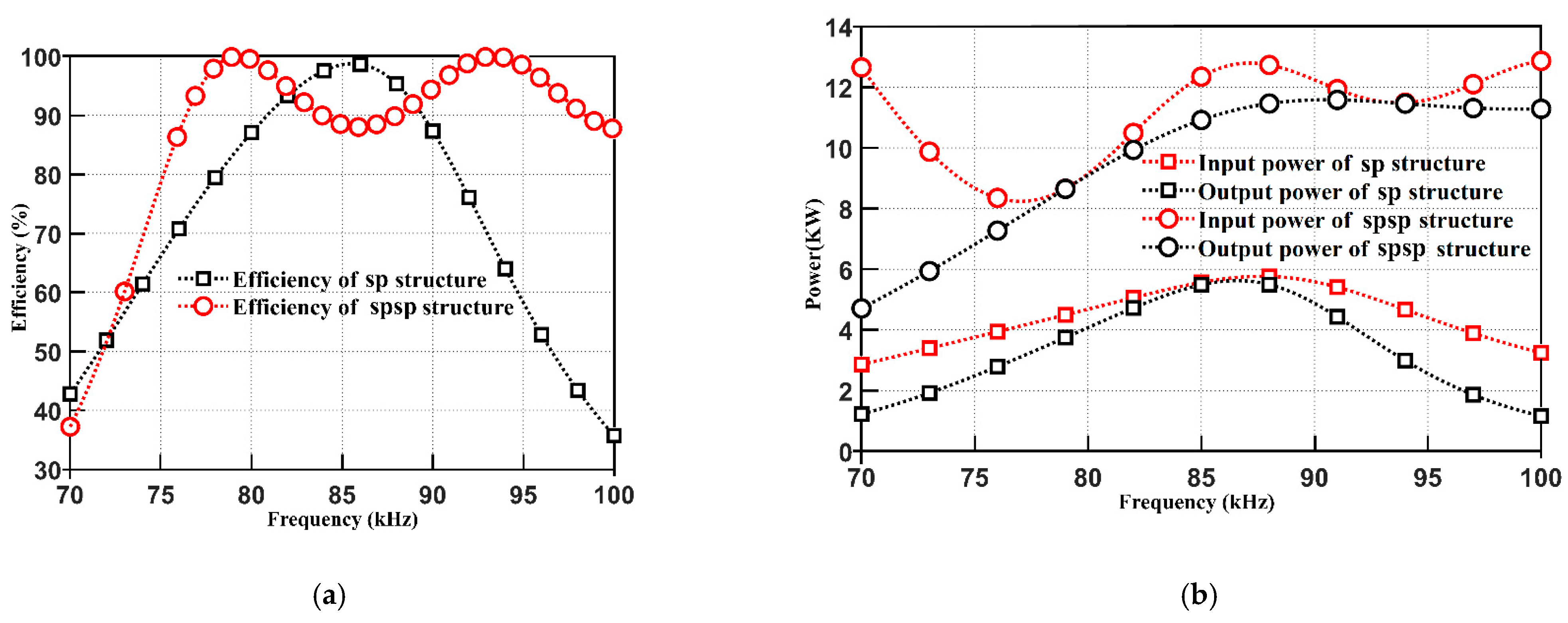
4.1. Frequency Characteristics Study

For the two resonant structures in the above design conditions, Figure 4a studies the effect of the resonant frequency of magnetically coupled structures on the transmission efficiency. With the sp structure working in the frequency range of 70–100 kHz, the efficiency curve changes similar to the sine function half cycle change trend. As the resonant frequency increases, the curve of the sp structure rises and then falls, and the transmission efficiency is maximum at a resonant frequency of 87 kHz. It can be seen that the sp structure has better transmission characteristics between 77 and 92 kHz, the sp structure works in the frequency range of 70–100 kHz, the transmission characteristics are better between 75 and 100 kHz, and the transmission efficiency is always greater than The reason for the unstable efficiency between 79 and 92 kHz is the small internal resistance or the oscillatory drift of the frequency. Figure 4b shows the variation curve of transmission power versus resonant frequency for the two magnetically coupled structures. It can be seen that when the operating frequency is between 70 and 100 kHz, the output power of the spsp structure first increases and then remains stable at 11 kW, with the input power oscillating as a result of larger losses, while the output power of the sp structure first increases and then decreases, with a maximum power of approximately 5.8 kW, indicating that the sp structure transmission power is on the low side.

4.2. Characterization of the Coupling Coefficient

From Figure 4, it can be seen that both magnetically coupled resonant structures have good transmission characteristics in the frequency interval 77–92 kHz, and this frequency band will be used for the research and analysis of magnetically coupled systems in the following. As can be seen from Figure 5a,c, the coupling coefficient varies from 0 to 1, and when the load resistance is constant, the transmission efficiency of the spsp resonant structure system remains stable after growth, and the transmission efficiency is high and almost unaffected by the power supply frequency. While the sp structure with the coupling coefficient increases, the transmission efficiency first increases and then decreases, and the transmission efficiency is lower. The overall transmission efficiency of the spsp structure is higher than the sp structure, the spsp structure is more suitable for long-distance transmission, and the use of the spsp structure has more advantages in improving the transmission efficiency. From Figure 5b,d, it can be seen that the overall output power of the system is higher in the spsp structure, with a maximum output power of 15 kW when the coupling coefficient is 0.35, while the output power of the sp structure is significantly affected by the resonant frequency, with a maximum output power of 6 kW, i.e., the frequency stability of the spsp structure is better than that of the sp structure.

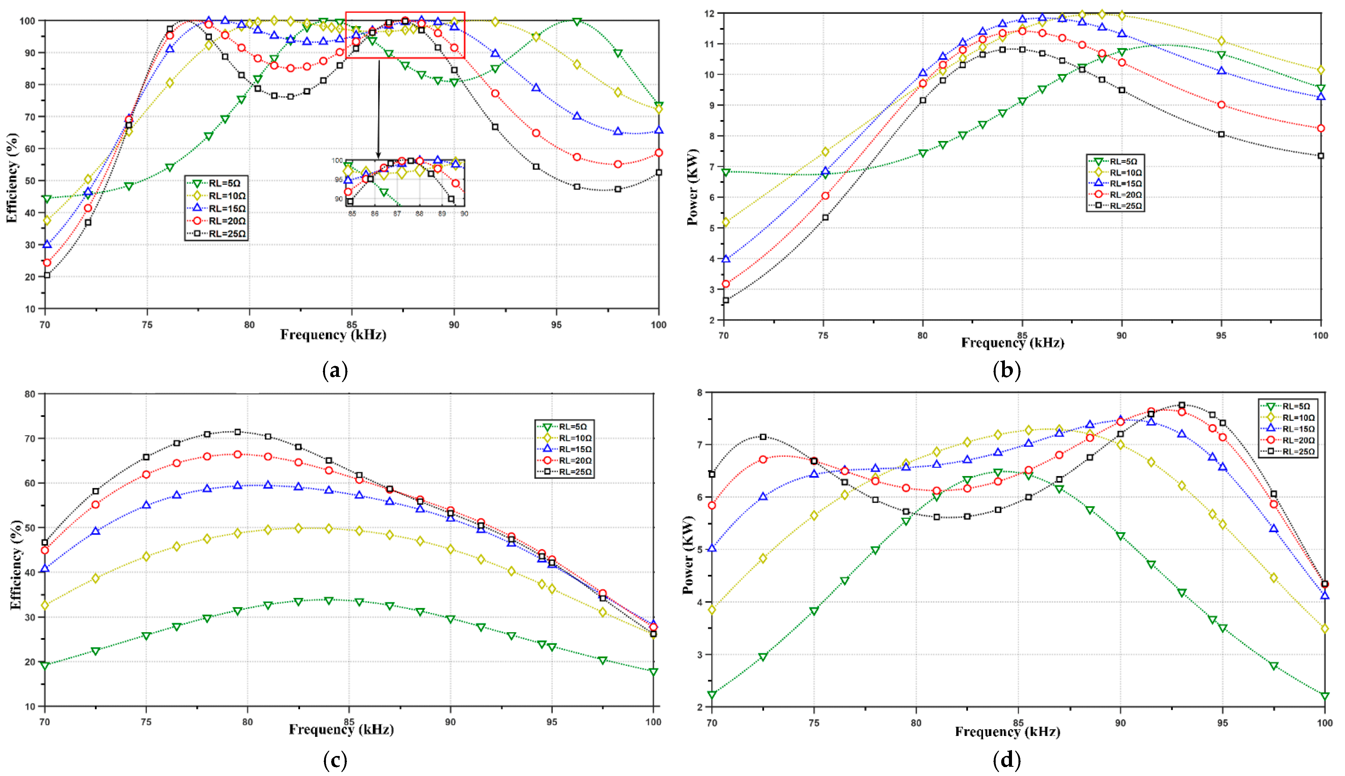
4.3. Load Resistance Characteristics Study

When most systems in real life are formed, the corresponding impedance values are determined. The load resistance value corresponding to the highest transmission efficiency of the system is the impedance matching value of the system. However, in the practical application of wireless energy transmission systems, the load resistance value varies within a certain range. In order to ensure that the magnetically coupled resonant structure can be flexibly adapted to the load, the relationship between load resistance and transmission efficiency, and transmission power will be investigated. As seen in Figure 6a,c, the spsp structure has a transmission efficiency above 75% at operating frequencies of 70–92 kHz under different load resistance values, while the sp structure has a large fluctuation in the transmission efficiency curve as the load resistance value changes, with a maximum transmission efficiency of 71%. As seen in Figure 6b,d, the power curve of the sp structure fluctuates more with the change in load resistance, and the change in load has less impact on the performance of the spsp structure than the sp structure. It indicates that the spsp structure is superior to the sp structure. The spsp topology is suitable for long-distance transmission and does not require high power supply stability, and the load variation has little effect on the performance of the structure.

5. Multi-Objective Parameter Optimization of Systems Based on the Improved Grey Wolf Optimization Algorithm

The design of magnetically coupled structural systems is a multi-parameter, multi-objective optimization problem, and the multiple objectives are often coordinated with each other. In this paper, the resonant frequency, coupling coefficient, and load resistance are used as optimization variables, and the degree of adaptation is defined as the transmission efficiency, and then a multi-objective optimization mathematical model of the system is established by integrating the constraint function and the optimization objective function. The spsp topology magnetic coupling structure is used for optimization, and the multiple objective functions are given different weights in combination with the actual application requirements, and then a set of optimal solutions is calculated for design reference, providing a basis for the comprehensive performance of the system to be optimized.
The strong convergence performance of the Gray Wolf optimization algorithm, simple structure, less parameters to be adjusted, the existence of convergence factors and information feedback mechanisms that can be adaptively adjusted, and the ability to achieve a balance between local search and global search, so that the solution accuracy and convergence speed of the magnetically coupled resonant radio energy transmission system have good performance, so the following will use the Gray Wolf optimization algorithm for parameter optimization.

5.1. Grey Wolf Optimization Algorithm Model

Mirjalili et al. (2014) [25] proposed a new intelligent optimization algorithm, inspired by the grey wolf in the animal world, called the Grey Wolf Optimizer (GWO), which is inspired by the grey wolf in the animal world. Mimicking the leadership hierarchy and hunting mechanisms of the grey wolf in nature, four types of grey wolves are used to simulate the leadership hierarchy. There are also three main components: hunting prey, rounding up prey, and attacking prey. The algorithm has a relatively simple structure, requires relatively few parameters to be tuned, and can be tuned to find global and local optimal solutions. Three parameters are considered in the implementation of the algorithm, which is designed to calculate the fitness of individual grey wolves. In this paper, the Gray Wolf optimization algorithm, which can effectively avoid local optima, is applied to the transmission characteristics of magnetically coupled resonant electric vehicles by adjusting the parameters to achieve the optimal value of efficiency.
Social hierarchy: the first leader rank is A, the test rank is B, the rank of the scapegoating wolf is D, and the remaining candidate solution ranks are X. The optimal solution is α(A) according to the hierarchy. The pack prey poses the following equation for the roundup behavior:
D = | C x p ( t ) x ( t ) |
x ( t + 1 ) = x p ( t ) A D
where t is the current iteration, A and C are the coefficient vectors, x p ( t ) is the position vector of the prey and x is the position vector of the grey wolf, the A and C vectors are calculated as follows:
A = 2 a r 1 a
C = 2 r 2
where A decreases from 2 to 0 and r 1 , r 2 are random vectors of [0, 1]. The grey wolf uses the position of its prey to update its position and adjusts A and C to achieve the best current position, and the grey wolf is also able to update its position in the multi-dimensional space based on the position vector.
Grey wolves of class A generally make decisions to select their prey, and grey wolves of class B and D are involved in hunting activities, also using agent position vectors to update their positions in the mathematical model built.
D α = | C 1 x α x | , D B = | C 2 x B x | , D δ = | C 3 x δ x |
x 1 = x α A 1 ( D α ) , x 2 = x B A 2 ( D B ) , x 3 = x δ A 3 ( D δ )
x ( t + 1 ) = x 1 + x 2 + x 3 3
The grey wolf completes the hunt by attacking the prey when it stops moving. A is a random vector that takes values between [−2a, 2a] and the value of a is decreasing during the iteration, taking values in the range [0, 2]. A can find any current position that suits itself based on its current position and the position of its prey, in the range of values [−1, 1].
Prey search: mostly separate prey searches based on A, B, and D, converging to attack prey, using random values greater than 1 or less than 1; to force the A search to deviate from the prey, and allowing a global search when A is greater than 1, forcing the grey wolf to deviate from prey and find better prey, while C contains random values of [0, 2], also component to provide random weights for prey. There is more random selectivity throughout the optimization process, facilitating exploration and avoidance of local optima, in contrast to A , where C is not linearly decreasing and can provide random values to facilitate search during iterations, which makes it easy to lift stagnation under conditions of local optima. In nature too, when wolves encounter an obstacle, it still hinders or stalls the pack’s pursuit of prey.

5.2. Ideas for Improving the Grey Wolf Optimization Algorithm Model

Mirjalili et al. (2016) [26] proposed a novel multi-objective algorithm called the multi-objective grey wolf optimizer in 2016. Ten challenging multi-objective test problems are used as benchmarks. Experimental results show that the multi-objective grey wolf optimization algorithm has superior convergence and coverage, and the coverage capability is confirmed by qualitative results. Hu et al. (2020) [27] proposed an improved binary grey wolf optimizer and an application for function selection. The Binary Grey Wolf Optimizer (BGWO) extends the application of the GWO algorithm and applies it to binary optimization problems. In this paper, the transmission characteristics of magnetically coupled electric vehicles are optimized using the grey wolf optimization algorithm. First, a random population of grey wolves (candidate solutions) is created in the grey wolf optimization algorithm GWO. During the iteration process, the possible locations of the estimated prey using the three wolves A, B, and D can be used to find the optimal value of efficiency by resistance, coupling coefficient, and frequency. The position is updated for each candidate solution. To explore and consider the optimal value, the parameter a is decreased from 2 to 0. When A is greater than 1, the candidate solution diverges from the target value and converges to the target value when A is less than 1.
Grey wolf packs have a very strict social hierarchy, similar to a pyramid. Using a modified binary grey wolf optimizer (BGWO) using a hierarchy, search and hunt prey mechanism, similar to that used by real wolves in nature, with positions located at any point in continuous space and selection constraints set to coupling coefficients, transmission efficiency, and load resistance, the optimizer aims to improve the system transmission efficiency of magnetically coupled resonant electric vehicles.
Using the same strategy to obtain the values of A, B and D, using the E q function and then using the Sigmoid function, the following equation is obtained:
s 1 d = 1 / ( 1 + e 10 ( A d D α d 0.5 ) )
s 2 d = 1 / ( 1 + e 10 ( A d D B d 0.5 ) )
s 3 d = 1 / ( 1 + e 10 ( A d D δ d 0.5 ) )
where the DTH dimension of the grey wolf of d, using the following values, rather than continuous values, is switched using the transfer function Equations (35)–(37), requiring values of 0 and 1 to be compared with random numbers.
b s t p 1 d = {   1 , i f ( s 1 d r a n d n ) 0 ,   e l s e
b s t p 2 d = {   1 , i f ( s 2 d r a n d n ) 0 ,   e l s e
b s t p 3 d = {   1 , i f ( s 3 d r a n d n ) 0 ,   e l s e
where r a n d n is a random number between [0, 1], and b s t p 1 d , b s t p 2 d   and b s t p 3 d are the distances moved relative to A, B, D. Next calculate:
X 1 d = { 1 , i f ( X α d + b s t p 1 d 1 )   0 ,     e l s e
X 2 d = { 1 , i f ( X β d + b s t p 2 d 1 )   0 ,     e l s e
X 3 d = { 1 , i f ( X β d + b s t p δ d 1 )   0 ,     e l s e
A random crossover is used in the iteration to update the position of X . The position of the next iteration is:
X i d ( n t ) = { X 1 d   i f ( r a n d < 1 / 3 ) X 2 d e l s e i f ( 1 / 3 r a n d < 2 / 3 ) X 3 d       e l s e

5.3. Improving the Grey Wolf Algorithm for Multi-Objective Parameter Optimization

In the Grey Wolf optimization algorithm, the magnetically coupled radio transmission system utilizes constraints for better optimization seeking efficiency, and at each iteration, the global optimum position is perturbed using the optimizer, increasing the probability of the algorithm jumping out of the local optimum. Secondly, adaptive step sizes are introduced to improve the algorithm’s optimization finding accuracy. The update mechanism of the position in the case of finding the optimal efficiency avoids the blindness of the current individual position update and enables a better search for the optimal solution transmission efficiency. The improvement strategy in this paper is to use the creation of a random grey wolf population as the candidate solution, use the Sigmoid function to find the position, use the transfer function to switch, provide random weights for the prey, and then disperse the candidate solution with the target value and select the constraints as the coupling coefficient, resonant frequency, and load resistance in the magnetically coupled electric vehicle WPT system. The test functions are carried out independently during the simulation tests. The stopping condition is set as follows: when the global optimum or local optimum corresponds to the number of iterations to find the optimal parameter value of the key parameter or to get the parameter value corresponding to the optimal solution.

5.3.1. Optimal Constraints

For the previous spsp topology system choosing the coupling coefficient, resonant frequency, and load resistance as the most constraining conditions, the following equation is obtained:
d i s p = [ ( k , f , RL ) ]

5.3.2. Adaptation Function

In order to improve the transmission efficiency of the system, the fitness function is the transmission efficiency, which gives:
M a x ( f ) = P o u t P i n
This relationship is the objective function, which represents the ratio of the power obtained by the load to the power provided by the power supply. The following equation can be calculated:
{ U m = I a ( r s + j w L 01 + 1 j w C 01 ) + ( I a I a 1 ) ( 1 j w C 0 )     j w M I a 1 = I a 2 ( j w L 1 + 1 j w C 1 ) + I a L ( j w L 11 + R L ) j w M I a 1 = I a 2 ( j w L 1 + 1 j w C 1 + 1 j w C 01 ) I a L ( 1 j w C 11 )
{ 70 , 000 f 100 , 000 3 R L 20 0 < k 1

5.4. Optimization Simulation of Magnetically Coupled Resonant Systems

Because the previous simulation is only a single objective parameter obtained spsp structure and sp structure of the transmission curve graph, to study the three parameters optimal matching problem, the following improved grey wolf optimization algorithm is used with the purpose of multi-objective optimization, so that the transmission efficiency increases, and hopefully has some reference value for the selection of parameters of the magnetically coupled resonant wireless transmission system. Figure 7 shows the curve of the system adaptation (transmission efficiency). Table 2 shows the results of the comparison between the experimental analysis and the experimental optimization.
The grey wolf optimization algorithm uses the improved mathematical model working parameters as shown in Table 2. The results from Figure 7 and Table 2 show that the transmission efficiency of the system can be improved simultaneously with the improved grey wolf optimization algorithm when f = 80 kHz, k = 0.33447 and R L = 12 Ω . The transmission efficiency of the system is stable at 90.53%. Compared with the unimproved spsp structure model, the transmission efficiency is improved by 12%, thus demonstrating that in magnetically coupled resonant radio energy and parametric systems, the use of the improved grey wolf optimization algorithm can bring optimization to the system and that the transmission efficiency of the system can be optimized relatively quickly using this method.

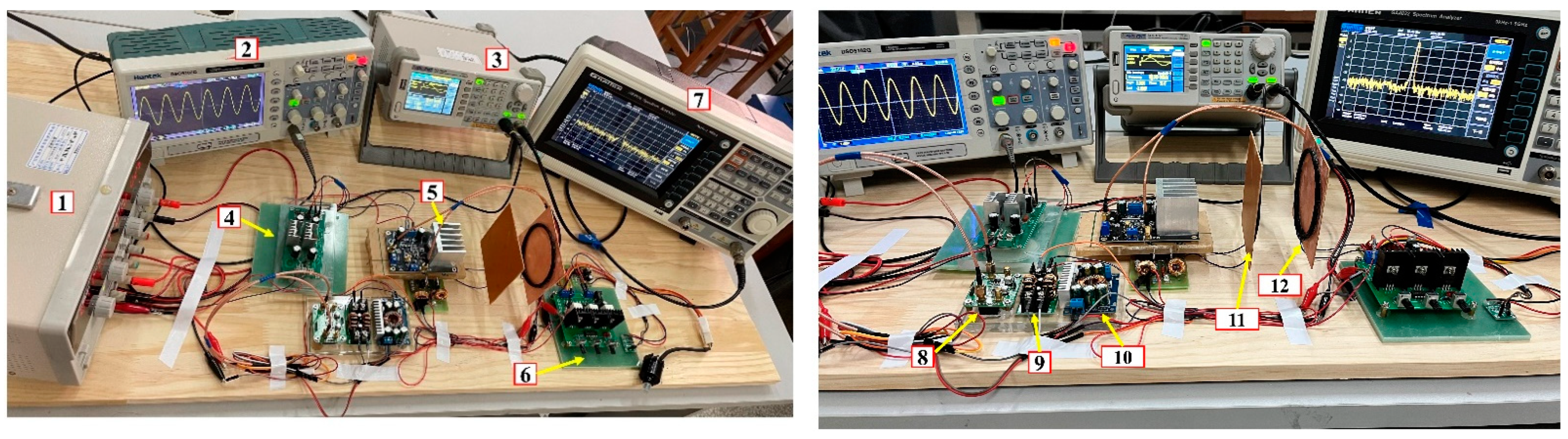
6. Experimental Validation

In order to verify the effectiveness of the improved Grey Wolf optimization algorithm for the improved magnetic coupling model, a magnetically coupled resonant coil system with an spsp structure was designed for verification. The parameters of the experimental platform were selected from the system parameters obtained through algorithm optimization. A coil with a diameter of 8.62 cm surrounded by copper wire of 2.5 mm diameter and a number of turns of 5 was selected for the experiment. The resonant frequency set by the spectrum analyzer was 80 kHz and the output voltage of the power supply was 220 V. The experimental platform built is shown in Figure 8. The main components of the prototype and the values of the coil circuit parameters are shown in Table 3.

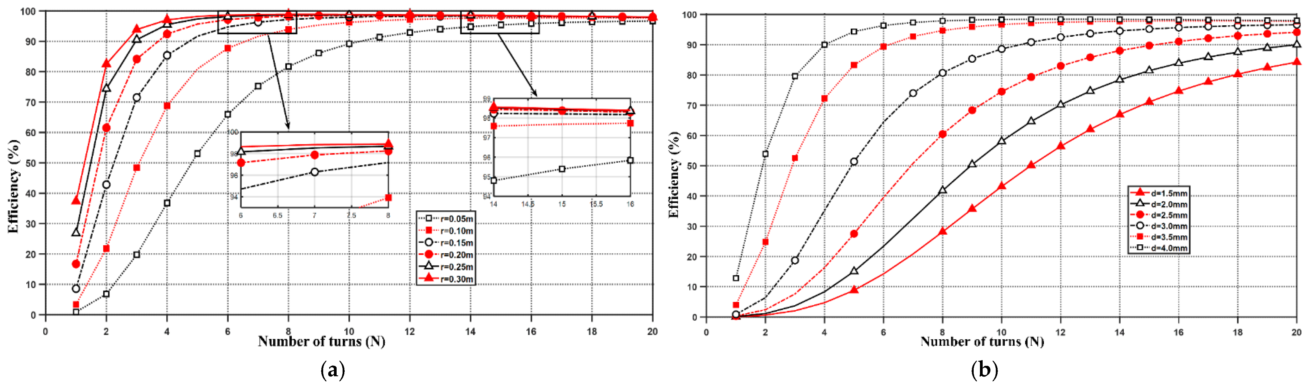
6.1. System Coil Structure Simulation Experiments

Based on the previous study, experiments will be carried out to optimize the magnetically coupled resonant coil. Different radii, number of turns, wire diameters, and lateral spacing between the receiving coil and the transmitting coil will be experimentally analyzed. The influence of structural parameters in the resonant coil on the transmission efficiency of the magnetically coupled system will be investigated to optimize the resonant coil structure, in the hope of contributing to the transmission and optimization of wireless energy.
Next, the parameters optimized by the grey wolf optimization algorithm were selected for coil simulation experiments, with the power supply frequency fixed at the frequency optimized by the grey wolf optimization algorithm. As can be seen from Figure 9, the effect of the number of turns, coil radius, and coil wire diameter on the transmission efficiency of the magnetically coupled structural system coil is investigated. r represents the radius and d represents the wire diameter. From Figure 9a, the graph shows that as the number of turns of the coil increases from 1 to 20, the transmission efficiency continues to increase as the coil radius increases from 5 to 30 cm. The reason for this is that an increase in radius increases the amount of flux transmitted from the transmitting coil to the receiving coil, and at a certain effective transmission distance, increasing the number of turns of the coil increases the transmission efficiency. From Figure 9b, the graph shows that at a certain effective distance, the transmission efficiency increases as the number of turns of the coil and the diameter of the coil wire continue to increase. The reason for this is that the larger the coil diameter d is, the lower the losses in the coil itself and the higher the conductivity, thus increasing the transmission efficiency.
As seen in Figure 10a, the greater the transmission distance, the different coil radii have different effects on the transmission efficiency. By choosing different coil radii, the efficiency can be kept at a higher level when the transmission distance is longer. Figure 10b shows the efficiency curve resulting from optimizing the coils. The coil radius is optimized first and then the number of turns is optimized. If the transmission distance is long, the appropriate coil radius is chosen, the optimum number of turns is found after the coil radius has been determined, and then the coil radius is optimized a second time.

6.2. Experiments with Offset Distances between Coils

Because in magnetically coupled systems, the transmission efficiency can be made higher at the right transmission distance. The following physical experiments will be carried out based on the offset distance between the transmitting and receiving coils. The receiving resonant coil will be offset left to right and longitudinal to the transmitting coil, the transmission efficiency decreases as the transmission distance increases and the actual measured data will be shown in the form of a figure.
Figure 11a shows the graph of the transmission efficiency obtained by shifting the secondary receiving coil around the primary transmitting coil left and right. The coil diameter of the primary and secondary compensation coils is 8.62 cm, and when the left and right offset distance is greater than 8.62 cm, the transmission efficiency is 0. The reason is that the two coils cannot reach a resonant state for energy transmission. As can be seen from Figure 11a, the blue 1 bar graph shows the left offset of the receiving coil, with the transmission efficiency dropping from 100% to approximately 70% as the left offset distance goes from 0 to 5 cm. With the left offset from 5 to 8.62 cm, the misalignment between the two coils is so large that the only way to transmit energy is to compensate for the coil, and the transmission efficiency drops continuously to approximately 20%. Additionally, the yellow No. 2 bar graph shows the right offset of the receiving coil, the transmission efficiency drops from 100% to approximately 75% when the offset distance is (0–5 cm), and gradually decreases when the offset distance is from 5 to 8.62 cm, the reason is that the two coils are offset too much and the magnetic coupling resonance area is too small and already close to completely misaligned.
Figure 11b plots the transmission efficiency obtained by offsetting the receiving coil longitudinally around the transmitting coil by a distance. The blue bars show the analysis of the data measured in the prototype experiment, while the red bars show the analysis of the data from the theoretical simulation experiment. The transmission efficiency decreases as the longitudinal offset distance from 0 to 15 cm in the theoretical simulation experiment, dropping from 99% to approximately 87% as the longitudinal offset goes from 0 to 5 cm. When the longitudinal offset is from 5 to 12.5 cm, the efficiency keeps changing steadily with less variation and the system is more stable. At longitudinal offsets from 12.5 to 15 cm, the transmission efficiency gradually decreases and varies in magnitude. The reason for this is that the offset distance is too large, the coil itself has losses or the material of the coil is a problem.
The theoretical simulation experimental efficiency is 90.53%. In contrast, the average transmission efficiency in the physical experimental diagram of the prototype, calculated from data measurements, is 83.75%. The error is 6.78%. The error is due to the spectrum analyzer frequency variation in the experimental platform, the vertical distance between the coils and the distance of the coil center point in the horizontal direction (the so-called degrees of freedom), the degree of heating of the entire magnetically coupled system and the ambient temperature. The errors also remain within acceptable limits, verifying the validity of the application in magnetically coupled resonant wireless energy transmission systems.
A large amount of data was generated using the prototype experiments and the experimental data were measured in the laboratory in real time. As the experimental data were too large to be conveniently placed in the manuscript, the experimental data were uploaded in the form of an attached table. The experimental flowchart for this paper is shown in Figure 12.

7. Conclusions

In this paper, we aim to improve the transmission efficiency of the magnetically coupled resonant wireless energy transmission systems and optimize the system structure and multi-parameter matching problems. The principle of the transmission method is theoretically analyzed by using circuit coupling theory to make the wireless energy transmission system work in the best condition as a whole. Firstly, the spsp resonant topology applicable to the wireless energy transmission system is proposed, as well as the three key parameters affecting the system efficiency of the magnetically coupled resonant wireless energy transmission system: resonant frequency, coupling coefficient, and load resistance are studied by using Matlab simulation software. Then, with the aim of improving the system transmission efficiency, the key parameters are multi-objective optimized by using the improved Gray Wolf optimization algorithm to find the optimal matching values of the key parameters. Finally, a prototype physical system is established, and coil structure and coil offset experiments are conducted using the optimal matching parameters to verify the correctness of the theory and reliability of the experiments.
This study has certain advantages in the optimization of wireless energy transmission parameters and improvement of transmission efficiency. Based on the literature review and the problems raised by the school–enterprise cooperation project, a study of the magnetically coupled resonant wireless energy transmission system is carried out. Based on the review of a large number of references, the idea, structure and optimization method of this research paper are proposed, the theoretical structure is simulated and analyzed, and the experimental system is built to verify and conform to the scope of the literature review.
Most of the previous studies were aimed at optimizing a single determined parameter, while the research in this paper is aimed at managing the new structure, multi-objective influencing factors, by multiple key parameters and correlated with the actual electric vehicle, simulating the actual electric vehicle subject to multiple factors scenarios, in order to reach the optimal system transmission efficiency faster.
The present study only completes simulation experiments and prototype experiments in the laboratory, without considering the influence of temperature on the system performance, and without large-scale practical application. Future research will further improve the reliability of the system and ensure the stability of the experimental system under different temperatures. It is hoped that this paper will provide some guidance for the realization of magnetically coupled resonant radio energy transmission and optimization for electric vehicles.

8. Patents

Patent—A rotatable variable position wireless charging device for electric vehicles.

Author Contributions

Conceptualization, C.W. and M.C.; methodology, M.C.; software, M.C. and Q.X.; validation, M.C. and Q.X.; formal analysis, M.C.; investigation, C.W., M.C. and Q.X.; data curation, M.C. and Q.X.; writing—original draft preparation, M.C. and C.W.; writing—review and editing, M.C. and C.W. All authors have read and agreed to the published version of the manuscript.

Funding

This research was funded by National Natural Science Foundation of China (Grant Nos. 61662005) and Guangxi Key Laboratory of Hybrid Computation and IC Design Analysis (No. HCIC201713).

Data Availability Statement

The data that support the findings of this study are available from the corresponding author, M.C., upon reasonable request.

Acknowledgments

The authors are very grateful to the reviewers for their careful, unbiased and constructive advice, which has greatly assisted the revision of this manuscript.

Conflicts of Interest

The authors declare no conflict of interest.

References

  1. Kurs, A.; Karalis, A.; Moffatt, R.; Joannopoulos, J.D.; Fisher, P.; Soljacic, M. Wireless power transfer via strongly coupled magnetic resonances. Science 2007, 317, 83–86. [Google Scholar] [CrossRef] [PubMed] [Green Version]
  2. Karalis, A.; Joannopoulos, J.D.; Soljačić, M. Efficient wireless non-radiative mid-range energy transfer. Ann. Phys. 2008, 323, 34–48. [Google Scholar] [CrossRef] [Green Version]
  3. Liu, Z.; Chen, Z.; Peng, C.; Liang, J.; Xiao, P.; Bian, L.; Qiu, Y.; Li, G. A misalignment resilient system for magnetically coupled resonant wireless power transfer. IEEE Trans. Antenn. Propag. 2020, 68, 8260–8265. [Google Scholar] [CrossRef]
  4. Liu, Z.; Chen, Z.; Li, J.; Zhao, H. A shape-reconfigurable modularized wireless power transfer array system for multipurpose wireless charging applications. IEEE Trans. Antenn. Propag. 2018, 66, 4252–4259. [Google Scholar] [CrossRef]
  5. Sagar, M.; Islam, S.; Ouassal, H.; Omi, A.I.; Wisniewska, A.; Jalajamony, H.M.; Fernandez, R.E.; Sekhar, P.K. Application of Machine Learning in Electromagnetics: Mini-Review. Electronics 2021, 10, 2752. [Google Scholar] [CrossRef]
  6. Lu, C.; Huang, X.; Tao, X.; Liu, X.; Rong, C.; Zeng, Y.; Liu, M. Design and analysis of an omnidirectional dual-band wireless power transfer system. IEEE Trans. Antenn. Propag. 2020, 69, 3493–3502. [Google Scholar] [CrossRef]
  7. Cheng, C.; Zhou, Z.; Li, W.; Zhu, C.; Deng, Z.; Mi, C.C. A multi-load wireless power transfer system with series-parallel-series compensation. IEEE Trans. Power Electr. 2019, 34, 7126–7130. [Google Scholar] [CrossRef]
  8. Fu, M.; Yin, H.; Liu, M.; Wang, Y.; Ma, C. A 6.78 MHz multiple-receiver wireless power transfer system with constant output voltage and optimum efficiency. IEEE Trans. Power Electr. 2017, 33, 5330–5340. [Google Scholar] [CrossRef]
  9. Zhang, Z.; Pang, H.; Georgiadis, A.; Cecati, C. Wireless power transfer—An overview. IEEE Trans. Ind. Electr. 2018, 66, 1044–1058. [Google Scholar] [CrossRef]
  10. Zheng, Z.; Wang, N.; Ahmed, S. Adaptive Frequency Tracking Control with Fuzzy PI Compound Controller for Magnetically Coupled Resonant Wireless Power Transfer. Int. J. Fuzzy Syst. 2021, 23, 1890–1903. [Google Scholar] [CrossRef]
  11. Peng, C.; Chen, Z.; Liu, Z.; Wang, J.F.; Liang, J.; Li, C.; Tao, S.; Li, J. On the Load-Independence of a Multi-Receiver Wireless Power Transfer System. IEEE Microw. Wirel. Compon. Lett. 2019, 29, 563–565. [Google Scholar] [CrossRef]
  12. Monti, G.; Tarricone, L.; Dionigi, M.; Mongiardo, M. Magnetically coupled resonant wireless power transmission: An artificial transmission line approach. In Proceedings of the 2012 42nd European Microwave Conference, Amsterdam, The Netherlands, 29 October–1 November 2012; pp. 233–236. [Google Scholar]
  13. Yan, R.; Ma, W.; Yang, Q.; Zhang, X. Out-of-step optimization of magnetically coupled resonant wireless power transmission system. Chin. J. Electr. Eng. 2022, 1–10. [Google Scholar]
  14. Yang, J.; Chen, W. Output Control of Wireless Power Transfer System Based on Improved Artificial Bee Colony Algorithm. J. Power Supply 2021, 20, 173–182. [Google Scholar]
  15. Zhang, Y.; Wang, L.; Guo, Y.; Tao, C. Multi-Objective Optimization of Magnetic Coupler for Wireless Power Transfer System Based on NSGA-II Algorithm. Adv. Technol. Electr. Eng. Energy 2020, 39, 28–34. [Google Scholar]
  16. Wu, Z.; Yan, R.; Guo, X.; Cao, S. Analysis of Transmission Distance and Efficiency of Wireless Power Transfer System. Chin. J. Power Source 2020, 44, 1212–1216. [Google Scholar]
  17. Cui, S.; Song, B.; Wang, Z. Overview of Magnetic Coupler for Electric Vehicles Dynamic Wireless Charging. Trans. China Electrotech. Soc. 2022, 37, 537–554. [Google Scholar]
  18. Ni, C.; Chen, H.; Li, D.; Zhou, C. Structural Optimization of Tapered Resonant Coil in Magnetically Coupled Resonant Wireless Power Transfer System. J. Sichuan Univ. 2020, 57, 304–310. [Google Scholar]
  19. Zhang, Z.; Liu, J.; Li, Y. Design and Analysis of a Multi-Input Multi-Output System for High Power Based on Improved Magnetic Coupling Structure. Energies 2022, 15, 1684. [Google Scholar] [CrossRef]
  20. Nakamura, S.; Baba, K.; Miyaura, T. Automatic Resonance Compensation for Efficient WPT via Magnetic Resonance Coupling Using Flexible Coils. Energies 2021, 14, 5254. [Google Scholar] [CrossRef]
  21. Bilandžija, D.; Vinko, D.; Barukčić, M. Genetic-Algorithm-Based Optimization of a 3D Transmitting Coil Design with a Homogeneous Magnetic Field Distribution in a WPT System. Energies 2022, 15, 1381. [Google Scholar] [CrossRef]
  22. Jawad, A.M.; Nordin, R.; Jawad, H.M.; Gharghan, S.K.; Abu-Samah, A.; Abu-Alshaeer, M.J.; Abdullah, N.F. Wireless Drone Charging Station Using Class-E Power Amplifier in Vertical Alignment and Lateral Misalignment Conditions. Energies 2022, 15, 1298. [Google Scholar] [CrossRef]
  23. Feng, G.; Liu, Z.; Hou, Y.; Luo, X.; Sun, S.; Ding, R.; Yu, A. Parameter Optimization of Double LCC MCRWPT System Based on ZVS. Energies 2021, 14, 5309. [Google Scholar] [CrossRef]
  24. Sato, S.; Nakamura, S. Proposal of Wireless Charging Which Enables Magnetic Field Suppression at Foreign Object Location. Energies 2022, 15, 1028. [Google Scholar] [CrossRef]
  25. Mirjalili, S.; Mirjalili, S.M.; Lewis, A. Grey Wolf Optimizer. Adv. Eng. Softw. 2014, 69, 46–61. [Google Scholar] [CrossRef] [Green Version]
  26. Mirjalili, S.; Saremi, S.; Mirjalili, S.M.; Coelho, L.d.S. Multi-Objective Grey Wolf Optimizer: A Novel Algorithm for Multi-Criterion Optimization. Expert Syst. Appl. 2016, 47, 106–119. [Google Scholar]
  27. Hu, P.; Pan, J.-S.; Chu, S.-C. Improved Binary Grey Wolf Optimizer and Its Application for Feature Selection. Knowl.-Based Syst. 2020, 195, 105746. [Google Scholar] [CrossRef]
Figure 1. Model of the spatial magnetic field distribution in the coil.
Electronics 11 01940 g001
Figure 2. Structure of spsp magnetically coupled resonant circuit.
Electronics 11 01940 g002
Figure 3. Structure of the sp magnetically coupled resonant circuit.
Electronics 11 01940 g003
Figure 4. (a) Plot of efficiency versus resonant frequency for the spsp magnetically coupled structure and the sp magnetically coupled structure; (b) plot of power versus resonant frequency for the spsp magnetically coupled structure and the sp magnetically coupled structure.
Electronics 11 01940 g004
Figure 5. (a) Plot of coupling coefficient versus transmission efficiency for the spsp magnetically coupled structures; (b) plot of coupling coefficient versus transmission power for the spsp magnetically coupled structures; (c) plot of coupling coefficient versus transmission efficiency for the sp magnetically coupled structures; (d) plot of coupling coefficient versus transmission power for the sp magnetically coupled structures.
Electronics 11 01940 g005
Figure 6. (a) Plot of load resistance versus transmission efficiency for the spsp magnetically coupled structures; (b) plot of load resistance versus transmission power for the spsp magnetically coupled structures; (c) plot of load resistance versus transmission efficiency for the sp magnetically coupled structures; (d) plot of load resistance versus transmission power for the sp magnetically coupled structures.
Electronics 11 01940 g006
Figure 7. Transmission efficiency adaptation curve.
Electronics 11 01940 g007
Figure 8. Experimental platform for magnetically coupled resonant systems (1—DC power supply, 2—digital oscilloscope, 3—signal generator, 4—inverter circuit, 5—power amplifier, 6—load, 7—spectrum analyzer, 8—digital frequency meter, 9—filter circuit, 10—regulator circuit module, 11—transmitting resonant coil, and 12—receiving resonant coil).
Electronics 11 01940 g008
Figure 9. (a) Transmission efficiency curve of the system with different coil radii for different coil turns; (b) transmission efficiency of the system with different coil wire diameters for different coil turns.
Electronics 11 01940 g009
Figure 10. (a) Transmission efficiency curves obtained with different coil radii for different transmission distances before system optimization; (b) transmission distances obtained with different coil radii for different distances after system optimization.
Electronics 11 01940 g010
Figure 11. (a) The left-right offset of the receiver coil; (b) the longitudinal offset of the receiver coil.
Electronics 11 01940 g011
Figure 12. Experimental flowchart.
Electronics 11 01940 g012
Table 1. Detailed parameters for modeling.
U m (V) k R L ( Ω ) R s ( Ω ) L 0 ( μ H ) C 01 ( μ F ) R 2 ( Ω )
2200.351011.9633.30.02
L 1 ( μ H ) L 01 ( μ H ) L 11 ( μ H ) C 1 ( nF ) C 0 ( μ F ) C 11 ( μ F ) C p ( μ F )
2182.22720.83.33103
Table 2. Results of the experimental analysis and experimental optimization.
System ArchitectureParameter ConditionsOptimization Conditions
before Optimizationafter Optimization
spsp magnetically coupled resonant systemPopulation size30\
Iteration20\
Load resistance1012
Frequency70–100 kHz80 kHz
Coupling factor0.350.33447
Efficiency60–78%90.53%
Table 3. Parameter values for the main components and coil circuit of the prototype.
ParametersValue/ModelParametersValue/ModelParametersValue/Model
Digital OscilloscopesSDS1102X-E R L 12 Ω C 11 10.4 μ F
DCMN-3205D L 0 2.2 μ H C p 3 μ F
Signal generatorsSDG1025 C 01 33 μ F Coupling factor0.33
Spectrum AnalyzerGA40XX L 1 220 μ H Resonant frequency80 kHz
Voltage regulator modulesLM2596 L 01 2.2 μ H R s 1 Ω
Power amplifiersLM1875 L 11 27 μ H C 1 22 nF
LoadLight source loadDigital frequency metersOPA615 C 0 3.3 μ H
Publisher’s Note: MDPI stays neutral with regard to jurisdictional claims in published maps and institutional affiliations.

