Article

Using Zone Impedance Matching Technique to Improve the Power Transfer Capability of an Inductive Charging System over a Long Distance

1
Electrical Engineering Division, Department of Engineering, University of Cambridge, Cambridge CB3 0FA, UK
2
Department of Electrical and Electronic Engineering, The University of Hong Kong, Hong Kong 999077, China
3
College of Electrical Engineering, Zhejiang University, Hangzhou 310058, China
*
Author to whom correspondence should be addressed.
Electronics 2022, 11(13), 1982; https://doi.org/10.3390/electronics11131982
Submission received: 31 May 2022 / Revised: 20 June 2022 / Accepted: 22 June 2022 / Published: 24 June 2022
(This article belongs to the Special Issue Emerging Technologies in Wireless Power Transfer Systems)

Abstract

:
In many outdoor inductive charging applications, the objects can move quickly, and the environment can change unpredictably. It is therefore difficult to design a fast controller that tracks the change in mutual coupling between the transmitter and receiver. The diminished power delivery to the objects either leads to incomplete charging or prolongs the charging time. In this paper, the concept of a zone impedance matching technique is proposed. This technique pre-matches the transmitter coil to the desired coupling coefficients. Thus, the power transfer capability of the inductive charger can be maintained at a reasonably high level over a long transmission distance and under a wide receiver misalignment. Based on a three-coil inductive power transfer (IPT) system, the proposed concept is practically implemented with a simple control scheme. The proposed IPT system equips a multi-tap transmitter coil to provide flexibility in selecting different numbers of turns in the transmitter coil. The controller senses the currents of the transmitter coil and the repeater coil to determine the zone of impedance to adapt to the change in mutual coupling of the coils. A mathematical analysis is conducted to formulate the design procedures for the proposed system. Under a wide range of distance and misalignment conditions, practical measurement results verified that the proposed system achieves higher power delivery than an ordinary design.

1. Introduction

Wireless power transfer technology based on magnetic resonance has gained great interest in recent years. It has found applications in the charging of consumer electronic devices, medical implants, electric vehicles and drones [1,2,3,4]. Conventionally, a two-coil system is used, which includes a transmitter coil (Tx) and a receiver coil (Rx). It has been noted that the power transfer capability is highly dependent on the transmission distance and coil alignment [5,6,7,8,9,10,11,12]. The two-coil system is suitable for short-range power transmission with high alignment of the coils in order to maximize the power transfer efficiency [13]. When the transmission distance becomes larger or coil misalignments occur, the coupling coefficient between the coils becomes relatively small. The power transfer efficiency rapidly decreases in this case. Thus, a four-coil IPT system has been proposed and investigated in [14].
A four-coil IPT system consists of a drive coil and a load coil in addition to the transmitter and receiver coils. In [15], the researchers use a simple equivalent-circuit model to explain that these two additional coils bring two new coupling coefficients to the system, which can be used to achieve impedance matching. So far, the four-coil system based on impedance matching (which is referred to as the maximum power transfer theorem in [13]) has been demonstrated to be an effective way of extending the transmission distance. However, impedance matching is only achieved at a specific distance and/or specific misalignment conditions. To cope with this problem, several adaptive methods have been extensively studied. In [16,17,18], frequency tuning techniques are introduced. Maximum power transfer can be tracked when the transmission distance is varied. Note that this method is only effective in the over-coupled region of the system [16], and it requires a high-performance controller to find the optimal frequency. Without stringent physical size limitations, an impedance matching circuit that consists of multiple switches, inductors and capacitors is introduced in [19]. Another method involves physically changing the coupling coefficient between the drive coil and the transmitter coil or the coupling coefficient between the load coil and the receiver coil by mechanical devices [20], which could be difficult to implement in real applications. In [21,22,23], the authors investigate using different sizes of single-turn drive and load coils to obtain maximum power transfer under various distance or misalignment conditions. The control schemes need to be developed for practical use. A new attempt using a nonlinear resonant circuit is introduced in [24]. The voltage amplitudes across the nonlinear capacitor depend on the coupling coefficient. Thus, the resonance frequency of the resonators is automatically adjusted, and it allows the transmitter to deliver higher power to the receiver.
In this paper, the concept of a zone impedance matching technique is proposed. This technique pre-matches the transmitter coil to the desired coupling coefficients. The system includes a multi-tap transmitter coil, a repeater coil and a receiver coil. In a given distance and/or given misalignment conditions, the best number of turns of the transmitter coil will be selected. Thus, the power transfer capability of the inductive power transfer system can be maintained at a reasonably high level over a long transmission distance and under a wide receiver misalignment. Some additional features of the proposed design include the same surface placement of the transmitter coil and the repeater coil to avoid large space occupation and no requirement on the receiver current and voltage information to determine the control actions. The rest of the paper is organized as follows. The analysis of the conventional three-coil IPT system is summarized in Section 2 as the essentials of the fundamental theory for the system design. The schematic of the three-coil IPT system is introduced in Section 3. Section 4 discusses the corresponding control method. Experimental verification is presented in Section 5. Finally, the conclusions are given in Section 6.

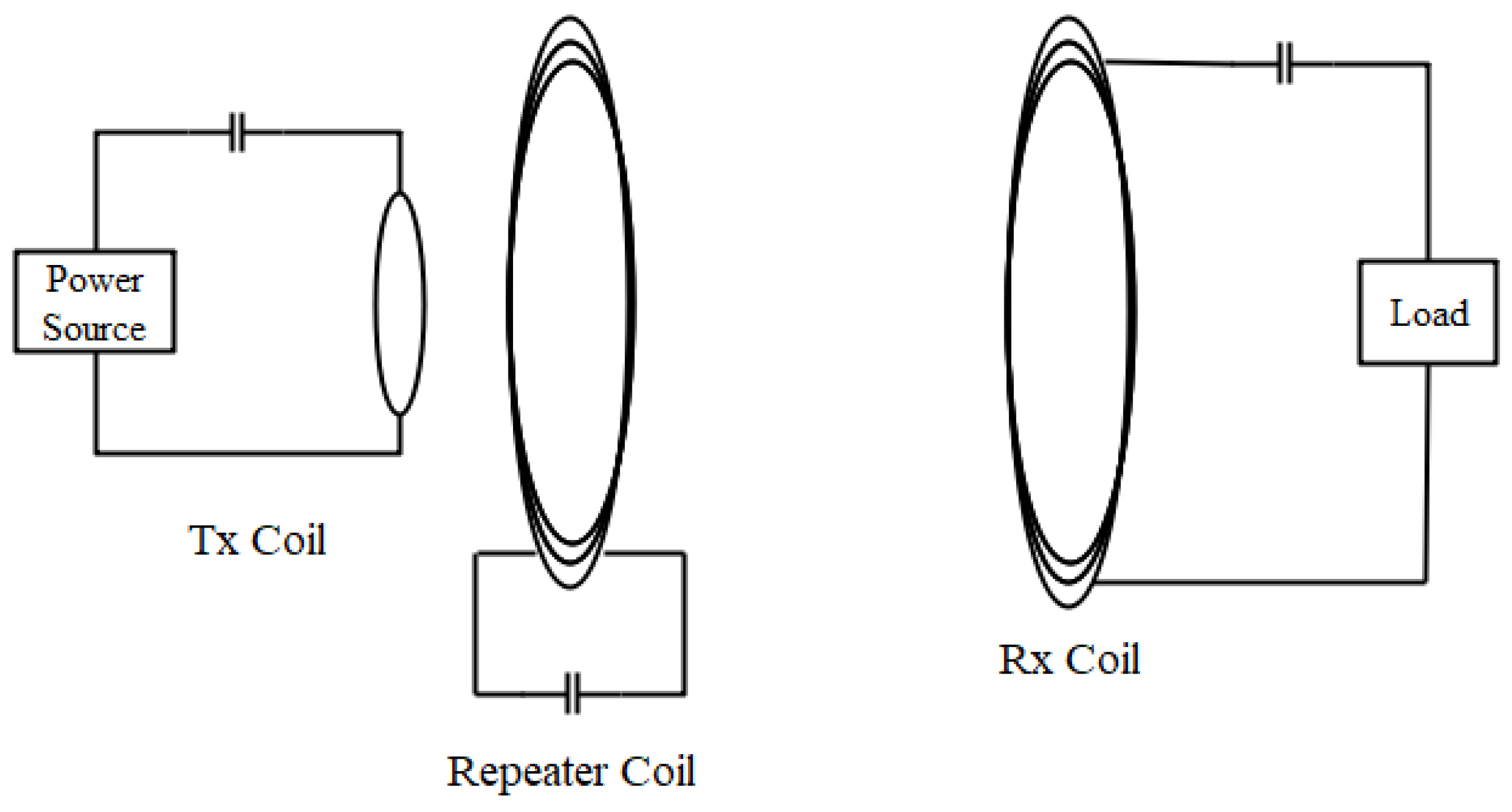
2. Conventional Three-Coil IPT System

Figure 1 shows the basic structure of a three-coil IPT system, which includes a transmitter coil, a repeater coil and a receiver coil. The transmitter coil and the repeater coil are placed at the transmitter side. Series-series compensation topology is used. The lumped circuit model of the three-coil system is shown in Figure 2. L n and R n (n = 1, 2, 3) are the self-inductances and parasitic resistances of the coils. C n is the external capacitor of each coil for tuning the resonant frequency, which is defined by (1). The coupling coefficient is defined by (2), which represents the strength of magnetic coupling between coils x and y . L x and L y are the self-inductances, and M x y is the mutual inductance. k 12 and k 23 are coupling coefficients between the transmitter coil and the repeater coil and between the repeater coil and the receiver coil, respectively. The transmitter coil is connected to a power source V s with an output impedance R s , and the receive coil is connected to a resistive load R L .
f 0 = 1 2 π L C
k x y = M x y L x L y
Based on the circuit model of a three-coil IPT system, the mathematical model is derived to represent the physical system. Impedance equations are expressed in (3), where ω is the angular frequency. Then, Kirchhoff’s voltage law is applied to determine the currents in each resonant circuit in (4). Afterwards, the system transfer function V L / V s can be obtained in (5). Since the number of turns and the radius of the transmitter are expected to be much fewer and smaller than the repeater coil, the influence of mutual inductance M 13 can be ignored. The k13 is neglected in the following analysis.
{ Z 1 = R s + R 1 + j ω L 1 + 1 j ω C 1 Z 2 = R 2 + j ω L 2 + 1 j ω C 2 Z 3 = R L + R 3 + j ω L 3 + 1 j ω C 3
[ Z 1 j ω M 12 0 j ω M 12 Z 2 j ω M 23 0 j ω M 23 Z 3 ] [ I 1 I 2 I 3 ] = [ V s 0 0 ]
V L V s = ω 2 k 12 k 23 L 2 L 1 L 3 R L Z 1 Z 2 Z 3 + ω 2 ( k 12 2 L 1 L 2 Z 3 + k 23 2 L 2 L 3 Z 1 )
An IPT system can be considered as a two-port network that transmits voltage waves from the source to the load through the coils [16]. The voltage gain of the system is presented by using scattering parameters S21, which is the forward voltage gain of a two-port network [25]. When the source impedance and the load impedance are equal, the system power-transfer-ratio η (PTR) can be expressed:
η = 4 V L 2 V s 2 R s R L = | S 21 | 2
{ Q 1 = ω 0 L 1 R s + R 1 Q 2 = ω 0 L 2 R 2 Q 3 = ω 0 L 3 R L + R 3
For a given three-coil IPT system operated at the resonant frequency, the coupling coefficients at which the system achieves the maximum power can be derived. Firstly, the quality factor (Q-factor) of the three coils at the resonant frequency are defined in (7). Then, the derivative | V L / V s | / k 23 = 0 from (5) at the resonant frequency can be solved. The critical coupling coefficient k c of the system can be obtained in (8). The system achieves maximum power when the value of k 23 is equal to k c .
k c = 1 Q 3 ( 1 Q 2 + k 12 2 Q 1 )

3. Multi-Tap Three-Coil IPT System

In many applications, the position of the receiver coil would be changed as the device moves. Therefore, k 23 varies in a range, and the power-transfer-ratio is low most of the time. To improve, a multi-tap transmitter coil based on the three-coil structure is proposed.

3.1. System Overview

Figure 3 shows the simplified schematic of the proposed system. The multi-tap transmitter coil, the repeater coil and the controller are integrated into a single device. The transmitter coil and the repeater coil are placed on the same surface, which minimizes the size of the transmitter. This design makes the system compact and easy to practically implement. Switches in the transmitter coil are controlled by a digital signal processor (DSP), such that the input impedance of the coil can be adjusted when the position of the receiver coil has been changed. The DSP only measures the currents information from the transmitter coil and the repeater coil to determine the tap position in order to adjust the inductance of the transmitter coil. A simple control method will be introduced in the next section.

3.2. Circuit Model

Figure 4 shows a lumped circuit model of the proposed three-coil IPT system. Different turns of the transmitter coil are modeled as L 1 i   ( i = 1 ,   2 ,   ) , and R 1 i represents the corresponding winding resistance. Only one switch will be turned on at any time, which means the optimum value of inductance will be chosen for the system at that particular coupling condition. A series-series compensation topology is used in this system. The capacitors C 1 i represent the external capacitors for different turns of the transmitter coil to operate at the same resonant frequency f 0 . The transmitter coil is connected to an AC voltage source V s . with a source impedance R s and is inductively coupled to the repeater coil with a coupling coefficient k 12 i . The L 2 and L 3 are the self-inductances of the repeater coil and the receiver coil, respectively. The R 2 and R 3 are the corresponding winding resistances. The C 2 and C 3 are the external capacitors that tune the coils’ resonant frequency to the resonant frequency of the transmitter coil. The k 23 is the coupling coefficient between the repeater coil and the receiver coil. The coupling coefficient k13 between the transmitter coil and the receiver coil is relatively small. Thus, it is neglected in this analysis. A resistive load R L is connected across the output of the receiver coil. Here, by replacing Z 1 and M 12 with Z 1 i and M 12 i in (3) and (4), the equations for the system will be derived. Rewriting the voltage gain V L / V s of the system, it can be expressed as (9).
V L V s = ω 2 k 12 i k 23 L 2 L 1 i L 3 R L Z 1 i Z 2 Z 3 + ω 2 ( k 12 i 2 L 1 i L 2 Z 3 + k 23 2 L 2 L 3 Z 1 i )
In a conventional three-coil IPT system, only k 23 changes in (5) when the transmission distance varies or misalignment occurs. Thus, the V L / V s decreases correspondingly, as indicated in (9). The proposed system would have selections of k 12 i , L 1 i and Z 1 i when k 23 changes. The system will automatically select the optimum values of k 12 i , L 1 i and Z 1 i to maintain the value of V L / V s , resulting in a higher power delivery than the conventional system.

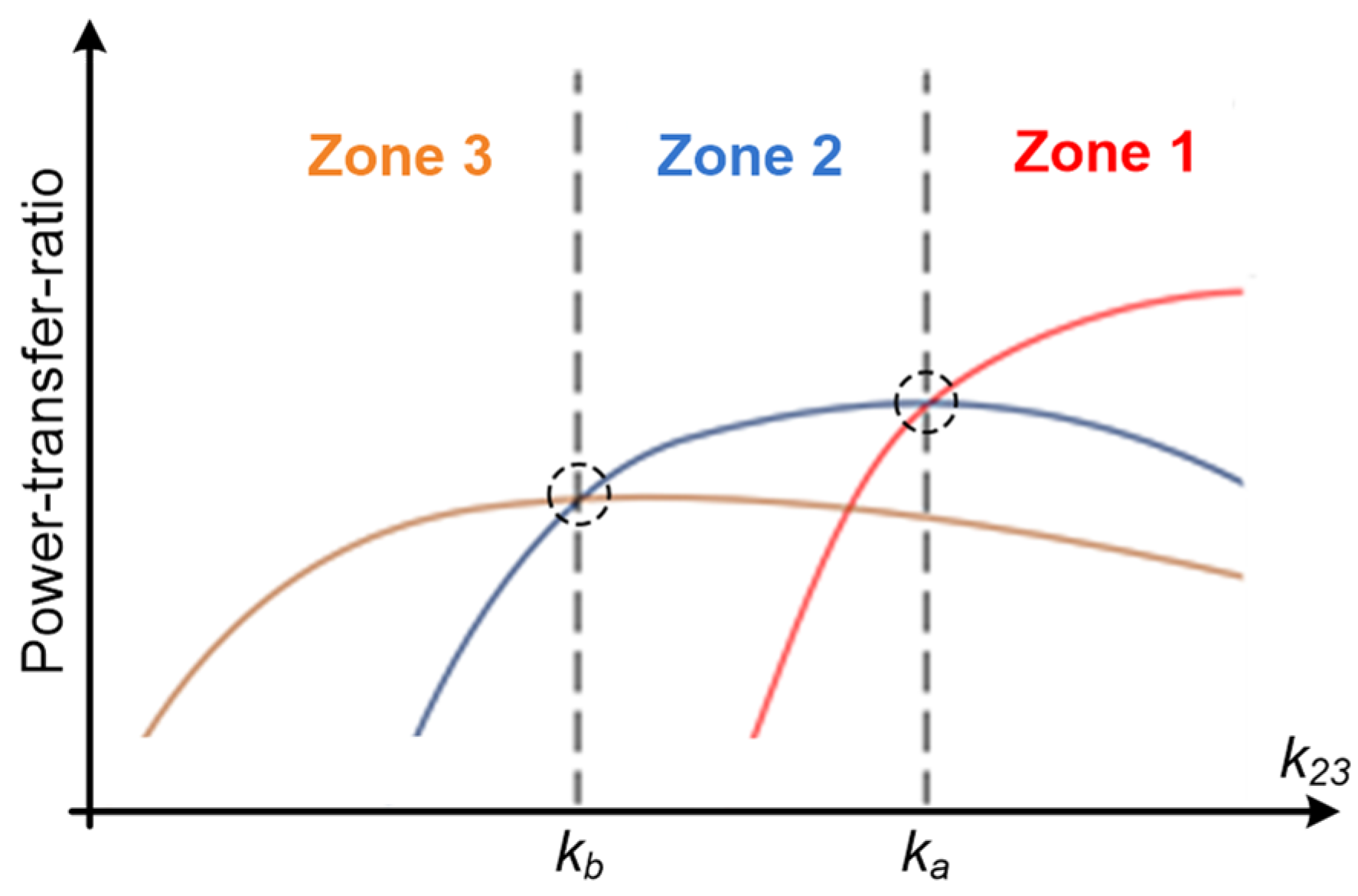
3.3. Desgin Methodology

According to the size requirements, the repeater coil and the receiver coil are pre-designed with a high Q-factor. To cope with different transmission distances and misalignment conditions, the concept of a zone impedance matching technique is proposed to pre-match the transmitter coil according to the value of k 23 . Firstly, the required Q-factor of the transmitter coil operating in the corresponding zone (i.e., Q 1 i ) is defined by using (10). The coupling coefficient k c i for the transmitter coil operating in the zone i is expressed in (11). According to the value of k 23 , the size and the number of turns of the transmitter coil can be determined. It can be observed that low self-inductance (a smaller number of turns) of the transmitter coil will be chosen when k c i is small, and vice versa.
Q 1 i = ω 0 L 1 i R s + R 1 i
k c i = 1 Q 3 ( 1 Q 2 + k 12 i 2 Q 1 i )
From the aspect of the input impedance, Z i n of the transmitter coil is expressed in (12) at the resonant frequency. The system reaches the maximum power when Zin equals the output resistance Rs of the high-frequency AC voltage source. Under a given M 23 (i.e., a given separation and misalignment between coils), the proposed system automatically selects a proper M 12 i to reduce the impedance mismatch. From (12), when M 23 is small, k 23 is small as well; then, a low self-inductance of the transmitter coil will be chosen to obtain a small M 12 i . This observation is consistence with (11). The multi-tap transmitter coil is designed to create more than one level of power to manipulate the k23 curves. The controller will direct the system to operate within the top regions of the curves by selecting a proper self-inductance of the transmitter coil when the distance changes or misalignment occurs.
Z i n = R 1 i + ω 0 2 M 12 i 2 ( R L + R 3 ) R 2 ( R L + R 3 ) + ω 0 2 M 23 2

4. Control Method

Figure 5 illustrates the power-transfer-ratio versus the k 23 curves of the system within three operating zones. If the value of k 23 is between k a and k b , Zone 2 is selected. Zone 3 is selected when k 23 is smaller than k b . Conversely, Zone 1 is selected when k 23 is larger than k a . The intersections of the curves represent the condition under which the system should change from one zone to another. Practically, it is important to deduce the value of k 23 by only using the information at the transmitter side. The transmitter coil is fixed with the repeater coil, so M 12 i can be measured. The equations for the system operating at the resonant frequency can be simplified to (13). Rewriting (13) gives M 23 in terms of I 1 and I 2 as shown in (14). I 1 and I 2 are the root-mean-square currents of the transmitter and repeater coils. Then, k 23 can be calculated by (2), and the optimum operating zone can be selected accordingly. The flow chart of the control method is shown in Figure 6.
[ R s + R 1 i j ω 0 M 12 i 0 j ω 0 M 12 i R 2 j ω 0 M 23 0 j ω 0 M 23 R L + R 3 ] [ I 1 I 2 I 3 ] = [ V s 0 0 ]
M 23 = ( R L + R 3 ) ( ω 0 M 12 i j R 2 I 2 ) j ω 0 2 I 2

5. Experimental Verification

5.1. Desgin Methodology

A proof-of-concept prototype was built to verify the performance of the proposed system (see Figure 7). A function generator (Tektronix AFG3102C) and a high-speed bipolar amplifier (HAS 4101) were used to provide an AC voltage source generating a sinusoidal wave with constant frequency and magnitude. The size of the repeater coil and the receiver coil were the same, each with a 10 cm radius in a helical structure. Litz wires were used to reduce the AC resistance in the coils. The number of turns of the coils was nine. The Q-factor of the coils reached 527 when the operating frequency was 585 kHz. All the parameters of the repeater coil and the receiver coil are shown in Table 1. The relationship between k 23 and transmission distance is shown in Figure 8a. The k 23 varied from 0.12 to 0.038 in the range of 10~20 cm. The value of k 23 versus the lateral misalignment from the center of the coil was also measured at the transmission distance of 10 cm. It varied from 0.12 to 0.036 with the misalignment from 0~14 cm, as shown in Figure 8b. A 3D plot of k23 versus both dimension changes is shown in Figure 9.
It was noted that a frequency-splitting phenomenon could happen when the coupling coefficient is high. Thus, the system operates in the over-coupled region. Frequency splitting requires special treatment in the control method in order to avoid the system operating at the incorrect operating point. To prevent the problems arising from frequency splitting, the maximum coupling coefficient at the shortest transmission distance should be limited to ensure the system always operates in the under-coupled region. In order to reduce the size of the transmitter, the transmitter coil was fixed with the repeater coil on the same surface. The transmitter coil consisted of multiple taps at two, three and four turns of the winding. Therefore, three inductances were available for the system. Without the misalignment, the mutual inductance at the shortest distance of 10 cm between the transmitter and receiver coils was measured as 0.85 μH. The corresponding k13 was 0.059. Figure 10 shows the frequency response of the system with and without the consideration of k13. It can be observed that the influence of the k13 at the resonant frequency was small. Ignoring the k13 in the analysis could simplify the solution such that the result can be easily implemented in a digital controller. The range of k23, the corresponding number of turns of the transmitter coil, k12 and M12 are summarized in Table 2. When the k23 was higher than 0.09, the system operated in Zone 1. The system operated in Zone 2 when the k23 was found between 0.09 and 0.06. When the k23 dropped below 0.06, the system operated in Zone 3. The detailed parameters of the transmitter coil, source impedance and load impedance are shown in Table 3. The resonant frequency of the resonators was measured by the Vector Network Analyzer to confirm that their value was close to 585 kHz.

5.2. Controller Desgin

Using Coilcraft current sensors CS1100L, the current waveforms in the transmitter and repeater coils were sensed. A peak detection circuit, as shown in Figure 11, was constructed to obtain the magnitude of the currents (i.e., I 1 _ p k and I 2 _ p k ). The rms values of the currents were calculated by a DSP TMS320F28069 from Texas Instruments. In order to remove the voltage ripple in the peak detection circuit, a digital averaging filter was applied. The DSP executed the calculation of Equation (14) to determine the best choice of transmitter coils. High-frequency relays TE 1462050-1 from Axicom were used to switch between various turns of the transmitter coil.

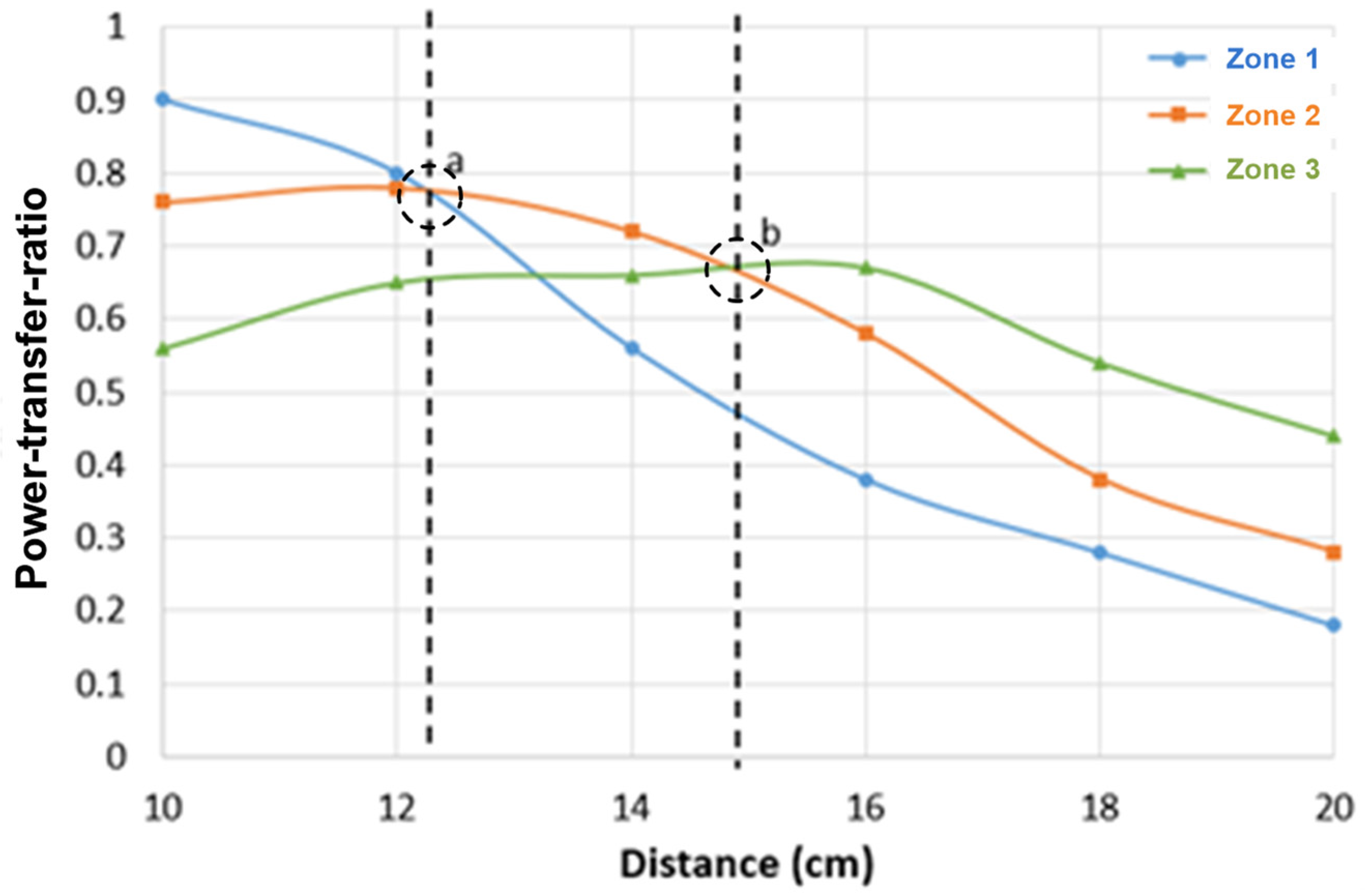
5.3. Results—Distance Variation

The magnitude and frequency of the AC power source were 12 V and 584.7 kHz, respectively. In the first experiment, the power-transfer-ratio over the distance was measured from 10 to 20 cm without lateral misalignment. Figure 12 shows the power-transfer-ratio from the transmitter coil to the receiver coil when the system was operated in three different operating zones. It can be observed that the PTR-to-distance curve of Zone 3 is flatter than Zone 1. This is because the Q-factor of the transmitter coil in Zone 1 was approximately three times higher than in Zone 3. The system changed the operating zones at the two intersection points, a and b, which were around distances of 12.5 cm and 15 cm, respectively. At point a, the transmitter coil changed from four turns to three turns to reduce k12 and M12 to adapt the transmission distance. It is clearly shown that the power-transfer-ratio of Zone 2 is higher than Zone 1 after point a. At point b, the transmitter coil further changed from three turns to two turns to maintain a high power-transfer-ratio. A combined system PTR-to-distance curve with DSP control was measured, and it is compared with the ordinary three-coil IPT system in Figure 13. It can be observed that the power delivery of the proposed system was significantly improved over a long distance. At distances of 14 cm and 18 cm, the power delivery was improved by 16 % and 26 %, respectively.

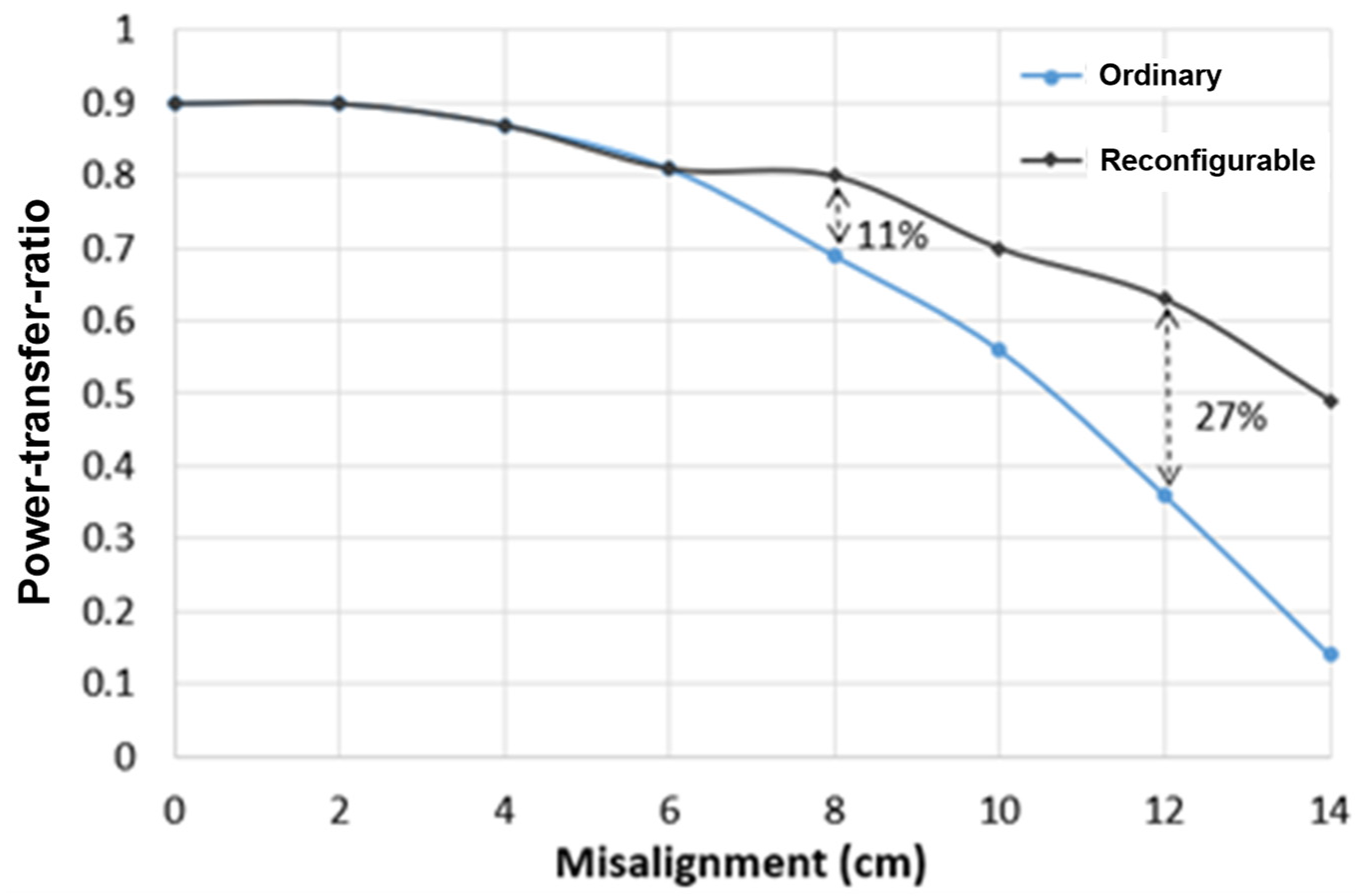
5.4. Results—Lateral Misalignment

In the second experiment, the power-transfer-ratio was measured when the distance was fixed at 10 cm, and the misalignment changed from 0 to 14 cm. The power-transfer-ratio from the transmitter coil to the receiver coil of the three operating zones is shown in Figure 14. The shapes of the three curves are similar to the PTR-to-distance curves in the first experiment. A combined system PTR-to-misalignment curve with DSP control was measured, and it is compared with the ordinary three-coil IPT system in Figure 15. The operating zone needed to be switched at misalignments of 6.5 cm and 10 cm. At misalignments of 8 cm and 12 cm, the power-transfer ratio of the proposed system was improved by 11 % and 27 %. Figure 16 shows a 3D plot of the measured power-transfer ratio versus both dimension changes.

6. Conclusions

With the use of a multi-tap transmitter coil and a zone impedance matching technique, the power transfer capability of an inductive charging system is improved over a long distance. The proposed system adaptively performs impedance matching to cope with the change of transmission distance and misalignment. The input impedance of the transmitter coil is selected by switching different taps of the transmitter coil. The transmission power is significantly increased compared with the ordinary structure. The control strategy uses the information from the transmitter to estimate the load position and select the proper turns of the transmitter coil. A proof-of-concept prototype was built to verify the proposed system and to evaluate the effectiveness of the control strategy. Experimental results confirmed that the proposed system performs well in the case of transmission distance variation and misalignment tolerance. Increasing the number of taps in the transmitter coil will bring more significant improvement. However, designers should pay attention to the Q-factor of the coils, which significantly influences the system performance. A further increase in the operating frequency reduces the physical size of the transmitter/receiver coils, which makes the proposal suitable for many medium-power and mid-range wireless charging applications, such as microrobots, implantable medical devices and drones.

Author Contributions

Conceptualization, J.H. and C.-K.L.; methodology, J.H., H.L. and R.W.M.N.; software, J.H.; validation, J.H., L.H. and C.-K.L.; formal analysis, J.H. and C.-K.L.; investigation, J.H.; resources, J.H.; data curation, J.H. and L.H.; writing—original draft preparation, J.H.; writing—review and editing, J.H. and C.-K.L.; visualization, J.H., L.H. and C.-K.L.; supervision, C.-K.L.; project administration, C.-K.L.; funding acquisition, C.-K.L. All authors have read and agreed to the published version of the manuscript.

Funding

This research was funded by University Grants Committee: Theme-based Research Scheme (T23-701/20-R).

Conflicts of Interest

The authors declare no conflict of interest.

Nomenclature

L n Self-inductance of nth coil
R n Parasitic resistance of nth coil
C n External capacitor of nth coil
k i j Coupling coefficient between ith coil and jth coil
M i j Mutual inductance between ith coil and jth coil
V s AC input voltage
R s Power source impedance
R L Load resistance
ω 0 Resonant angular frequency
f 0 Resonant angular frequency
V L Output voltage
Z i Total impedance of ith coil
Q i Quality factor of ith coil at the resonant frequency
L 1 i Inductance of different turns of transmitter coil
R 1 i Parasitic resistance of different turns of transmitter coil
C 1 i External capacitors for different turns of transmitter coil
Z 12 i Total impedance of different turns of transmitter coil
k 12 i Coupling coefficient between different turns of transmitter coil and repeater coil
M 12 i Mutual inductance between different turns of transmitter coil and repeater coil
Q 1 i Quality factor of different turns of transmitter coil
I i Current in ith coil

References

  1. Hui, S.Y.R. Planar wireless charging technology for portable electronic products and qi. Proc. IEEE 2013, 101, 1290–1301. [Google Scholar] [CrossRef] [Green Version]
  2. Wu, R.; Li, W.; Luo, H.; Sin, J.K.O.; Yue, C.C. Design and characterization of wireless power links for brain-machine interface applications. IEEE Trans. Power Electron. 2014, 29, 5462–5471. [Google Scholar] [CrossRef]
  3. Li, S.; Mi, C. Wireless power transfer for electric vehicle applications. IEEE J. Emerg. Sel. Top. Power Electron. 2015, 3, 4–17. [Google Scholar]
  4. Zhou, J.; Zhang, B.; Xiao, W.; Qiu, D.; Chen, Y. Nonlinear parity-time-symmetric model for constant efficiency wireless power transfer application to a drone-in-flight wireless charging platform. IEEE Trans. Ind. Electron. 2019, 66, 4097–4107. [Google Scholar] [CrossRef]
  5. Lee, C.K.; Zhong, W.X.; Hui, S.Y.R. Effects of magnetic coupling of non-adjacent resonators on wireless power domino-resonator systems. IEEE Trans. Power Electron. 2012, 27, 1905–1916. [Google Scholar] [CrossRef] [Green Version]
  6. Zhang, W.; Wong, S.C.; Tse, C.K.; Chen, Q. Design for efficiency optimization and voltage controllability of series-series compensated inductive power transfer systems. IEEE Trans. Power Electron. 2014, 29, 191–200. [Google Scholar] [CrossRef]
  7. Kissin, M.L.G.; Boys, J.T.; Covic, G.A. Interphase mutual inductance in polyphase inductive power transfer systems. IEEE Trans. Ind. Electron. 2009, 56, 2393–2400. [Google Scholar] [CrossRef]
  8. Covic, G.A.; Boys, J.T.; Kissin, M.L.G.; Lu, H.G. A three-phase inductive power transfer system for roadway-powered vehicles. IEEE Trans. Ind. Electron. 2007, 54, 3370–3378. [Google Scholar] [CrossRef]
  9. Miller, J.M.; Onar, O.C.; Chinthavali, M. Primary-side power flow control of wireless power transfer for electric vehicle charging. IEEE J. Emerg. Sel. Top. Power Electron. 2015, 3, 147–162. [Google Scholar] [CrossRef]
  10. Jang, Y.; Jovanovic, M. A contactless electrical energy transmission system for portable-telephone battery chargers. IEEE Trans. Ind. Electron. 2003, 50, 520–527. [Google Scholar] [CrossRef] [Green Version]
  11. Covic, G.A.; Boys, J.T. Modern trends in inductive power transfer for transportation applications. IEEE J. Emerg. Sel. Top. Power Electron. 2013, 1, 28–41. [Google Scholar] [CrossRef]
  12. Lee, J.; Han, B. A bidirectional wireless power transfer EV charger using self-resonant PWM. IEEE Trans. Power Electron. 2015, 30, 1784–1787. [Google Scholar] [CrossRef]
  13. Hui, S.; Zhong, W.; Lee, C. A critical review of recent progress in mid-range wireless power transfer. IEEE Trans. Power Electron. 2014, 29, 4500–4511. [Google Scholar] [CrossRef] [Green Version]
  14. Kurs, A.; Karalis, A.; Moffatt, R.; Joannopoulos, J.D.; Fisher, P.; Soljacic, M. Wireless power transfer via strongly coupled magnetic resonances. Science 2007, 317, 83–86. [Google Scholar] [CrossRef] [PubMed] [Green Version]
  15. Cheon, S.; Kim, Y.H.; Kang, S.Y.; Lee, M.L.; Lee, J.M.; Zyung, T. Circuit-model-based analysis of a wireless energy-transfer system via coupled magnetic resonances. IEEE Trans. Ind. Electron. 2011, 58, 2906–2914. [Google Scholar] [CrossRef]
  16. Sample, A.P.; Meyer, D.A.; Smith, J.R. Analysis, experimental results, and range adaptation of magnetically coupled resonators for wireless power transfer. IEEE Trans. Ind. Electron. 2011, 58, 544–554. [Google Scholar] [CrossRef]
  17. Park, J.; Tak, Y.; Kim, Y.; Kim, Y.; Nam, S. Investigation of adaptive matching methods for near-field wireless power transfer. IEEE Trans. Antennas Propoagation 2011, 59, 1769–1773. [Google Scholar] [CrossRef]
  18. Dang, Z.; Qahouq, J.A.A. Modeling and investigation of magnetic resonance coupled wireless power transfer system with lateral misalignment. In Proceedings of the 2014 IEEE Applied Power Electronics Conference and Exposition—APEC 2014, Fort Worth, TX, USA, 16–20 March 2014; pp. 1317–1322. [Google Scholar]
  19. Yongseok, L.; Hoyoung, T.; Seungok, L.; Jongsun, P. An Adaptive Impedance-Matching Network Based on a Novel Capacitor Matrix for Wireless Power Transfer. IEEE Trans. Power Electron. 2014, 29, 4403–4413. [Google Scholar]
  20. Zhang, Y.; Zhao, Z. Frequency-splitting analysis of four-coil resonant wireless power transfer. IEEE. Trans. Ind. Appl. 2014, 50, 2436–2445. [Google Scholar] [CrossRef]
  21. Kim, J.; Choi, W.-S.; Jeong, J. Loop switching technique for wireless power transfer using magnetic resonance coupling. Progr. Electromagn. Res. 2013, 138, 197–209. [Google Scholar] [CrossRef] [Green Version]
  22. Park, B.-C.; Lee, J.-H. Adaptive impedance matching of wireless power transmission using multi-loop feed with single operating frequency. IEEE Trans. Antennas Propag. 2014, 62, 2851–2856. [Google Scholar]
  23. Dang, Z.; Cao, Y.; Qahouq, J.A.A. Reconfigurable Magnetic Resonance-Coupled Wireless Power Transfer System. IEEE Trans. Power Electron. 2015, 30, 6057–6069. [Google Scholar] [CrossRef]
  24. Abdelatty, O.; Wang, X.; Mortazawi, A. Position-Insensitive Wireless Power Transfer Based on Nonlinear Resonant Circuits. IEEE Trans. Micro. Theory Tech. 2019, 67, 3844–3855. [Google Scholar] [CrossRef]
  25. Kim, K.; Choi, H. High-efficiency high-voltage class F amplifier for high-frequency wireless ultrasound systems. PLoS ONE 2021, 16, e0249034. [Google Scholar] [CrossRef]
Figure 1. Basic structure of a three-coil IPT system.
Electronics 11 01982 g001
Figure 2. Circuit model of a three-coil IPT system.
Electronics 11 01982 g002
Figure 3. Simplified schematic diagram of the proposed reconfigurable three-coil IPT system.
Electronics 11 01982 g003
Figure 4. Circuit model of the proposed three-coil IPT system.
Electronics 11 01982 g004
Figure 5. Illustration of selection criterion of operating zones.
Electronics 11 01982 g005
Figure 6. Flow chart of the control method.
Electronics 11 01982 g006
Figure 7. (a) Experimental setup and (b) prototype.
Electronics 11 01982 g007
Figure 8. (a) k 23 versus transmission distance; (b) k 23 versus misalignment when distance is 10 cm.
Electronics 11 01982 g008
Figure 9. k 23 versus transmission distance and misalignment.
Electronics 11 01982 g009
Figure 10. Frequency response of the system with k13 = 0 and k13 = 0.059.
Electronics 11 01982 g010
Figure 11. The peak detection circuit.
Electronics 11 01982 g011
Figure 12. The power-transfer ratio from the transmitter coil to the receiver coil versus transmission distance in three operating zones.
Electronics 11 01982 g012
Figure 13. Measured power-transfer ratio from the transmitter coil to the receiver coil versus transmission distance.
Electronics 11 01982 g013
Figure 14. Measured power-transfer-ratio from the transmitter coil to the receiver coil versus misalignment in three operating zones.
Electronics 11 01982 g014
Figure 15. Measured power-transfer ratio from the transmitter coil to the receiver coil versus misalignment.
Electronics 11 01982 g015
Figure 16. A 3D plot of measured power-transfer ratio from the transmitter coil to the receiver coil versus transmission distance and misalignment.
Electronics 11 01982 g016
Table 1. Parameters of the repeater coil and the receiver coil.
ParametersValues
Radius of repeater coil10 cm
Turns of repeater coil9
L233 μH
R20.23 Ω
C22.25 nF
Radius of receiver coil10 cm
Turns of receiver coil9
L333 μH
R30.23 Ω
C32.25 nF
Table 2. k12, M12 and k23 in three operating zones.
ZonesNo. of Turnsk12M12k23
Zone 140.284.0 μHk23 ≥ 0.09
Zone 130.2743.1 μH0.06 < k23 < 0.09
Zone 120.2682.1 μHk23 ≤ 0.06
Table 3. Parameters of transmitter coil.
ParametersValues
Inner radius of transmitter coil5 cm
Outer radius of transmitter coil6 cm
Total turns of transmitter coil4
L1–16.2 μH
L1–23.8 μH
L1–31.9 μH
R1–11 Ω
R1–20.6 Ω
R1–30.3 Ω
C1–112 nF
C1–220 nF
C1–340 nF
R s 50 Ω
RL50 Ω
Publisher’s Note: MDPI stays neutral with regard to jurisdictional claims in published maps and institutional affiliations.

