
A Modified Marx Generator Circuit with Enhanced Tradeoff between Voltage and Pulse Width for Electroporation Applications

 , , ,
, , ,  ,
,
Abstract
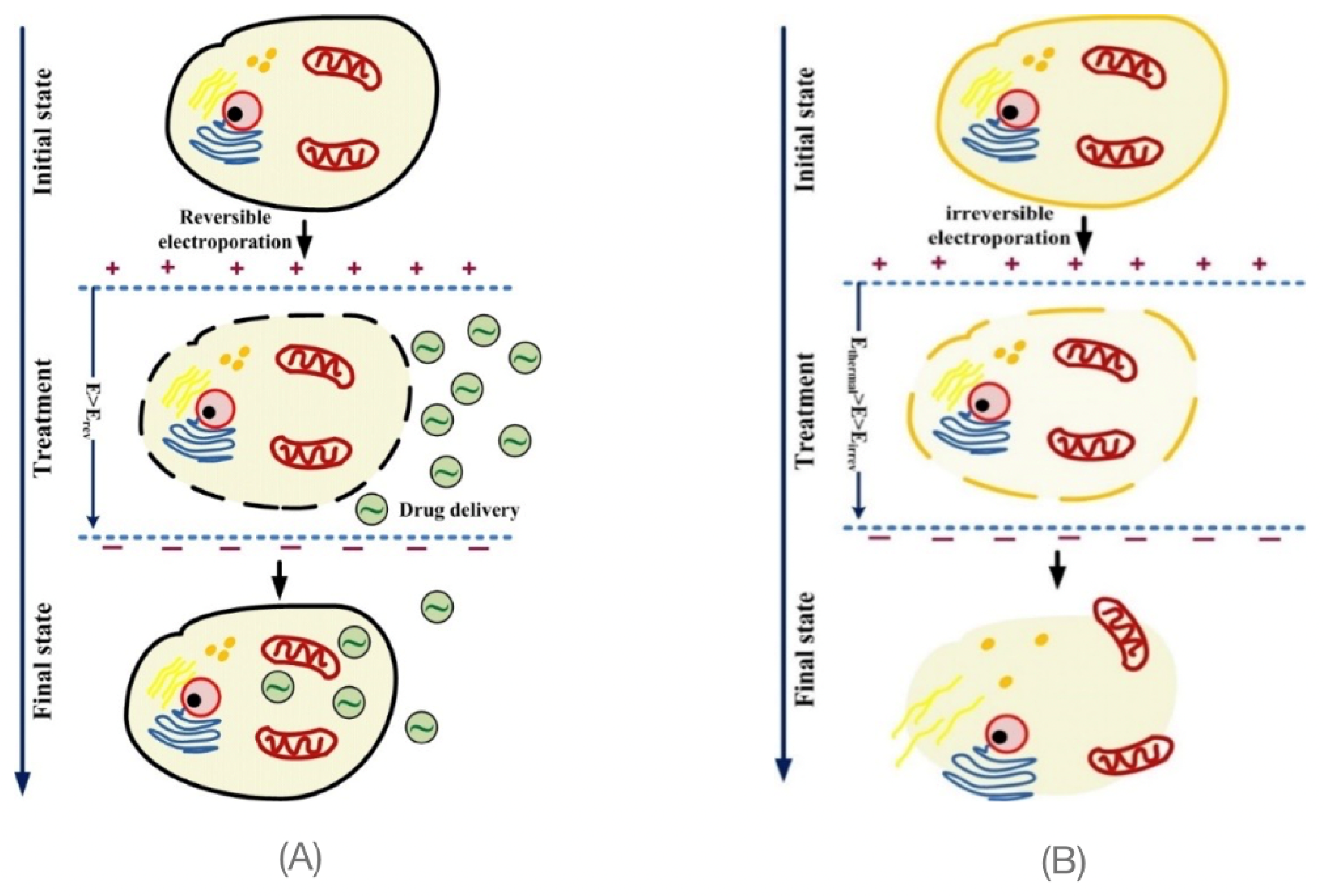
:1. Introduction
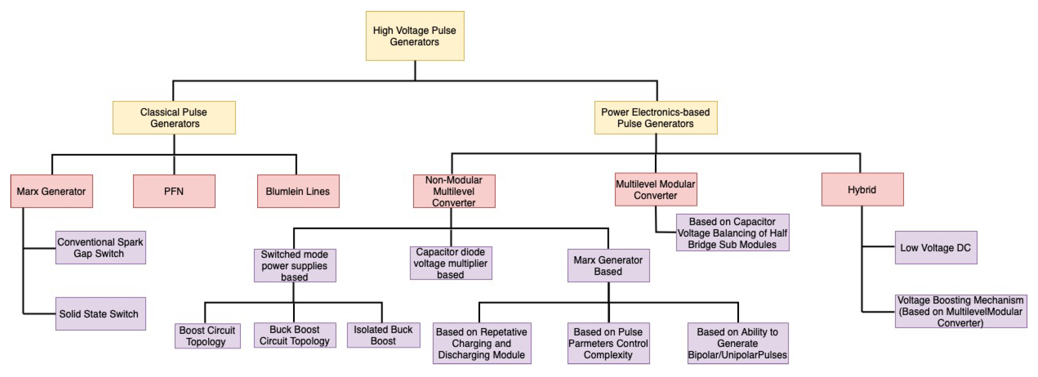
- Two Switch Pulse Generator [24]: It is based on two switches whose turn on time is controlled accurately. The duration of the pulse is determined by the delay between the switches.
- Linear Transformer Driver [29]: Here, magnetic fluxes generated from the discharge circuit are fed to a coaxial cable, so that the voltage is stacked up. By the changing the flux duration, we can vary the pulse properties.
- Marx Generator [30]: It is a widely used high voltage multiplier for fixed duration pulses. Recently, the spark gaps have been replaced by solid state switches, so that the pulse duration can be adjusted flexibly. In the lower voltage range (<10 kV), solid state switches are the top choice for hard switching, as they can be turned on and switched off, allowing for precise control of the pulse duration.
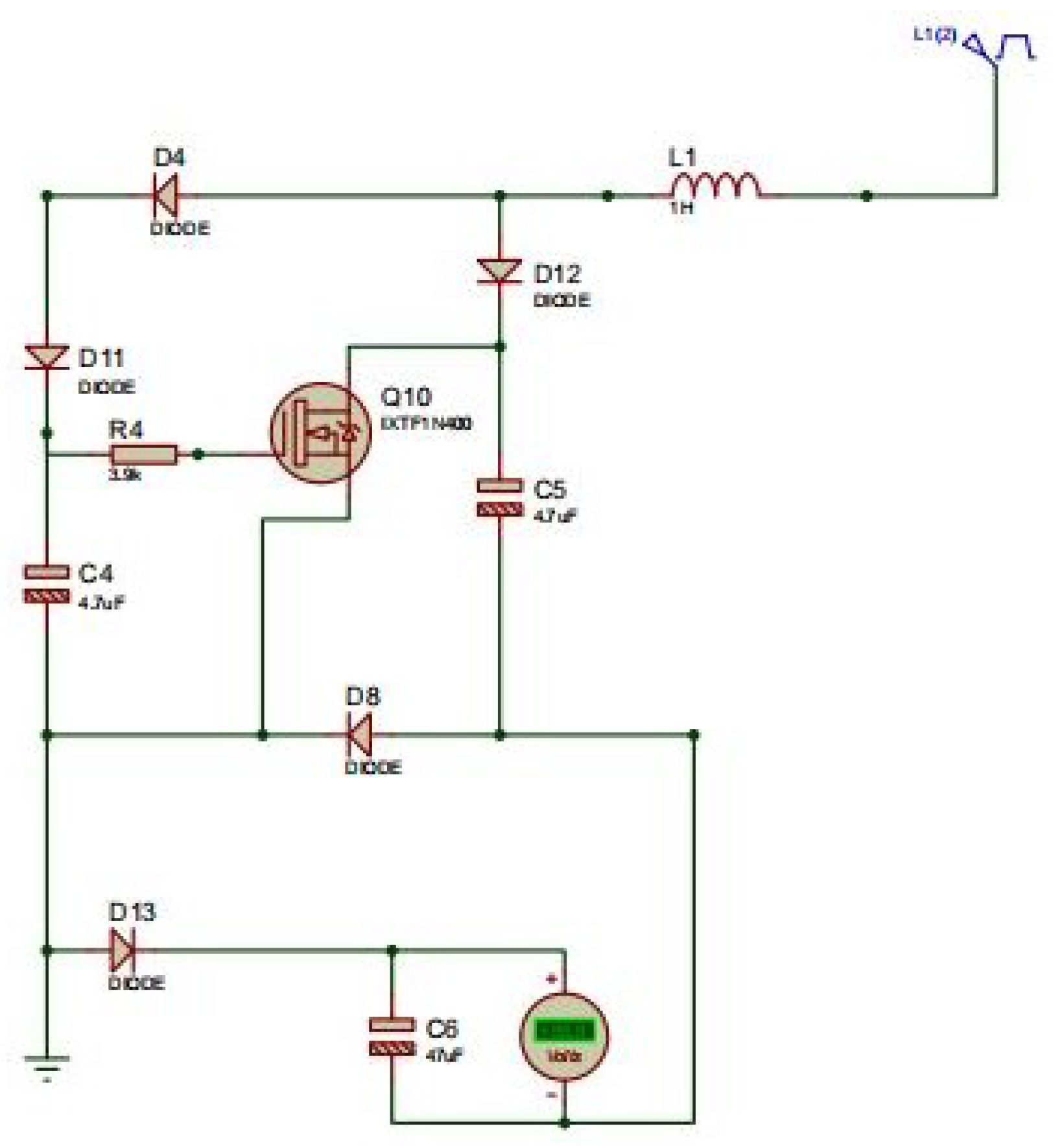
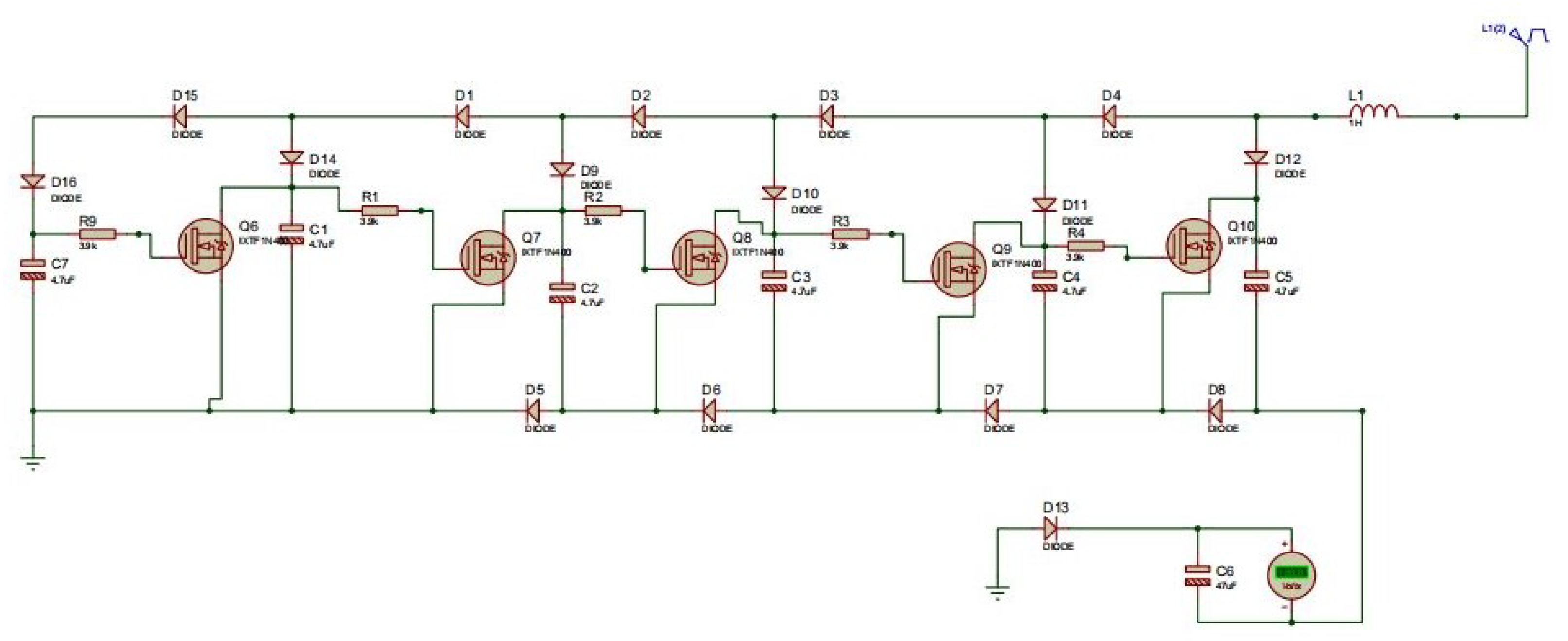
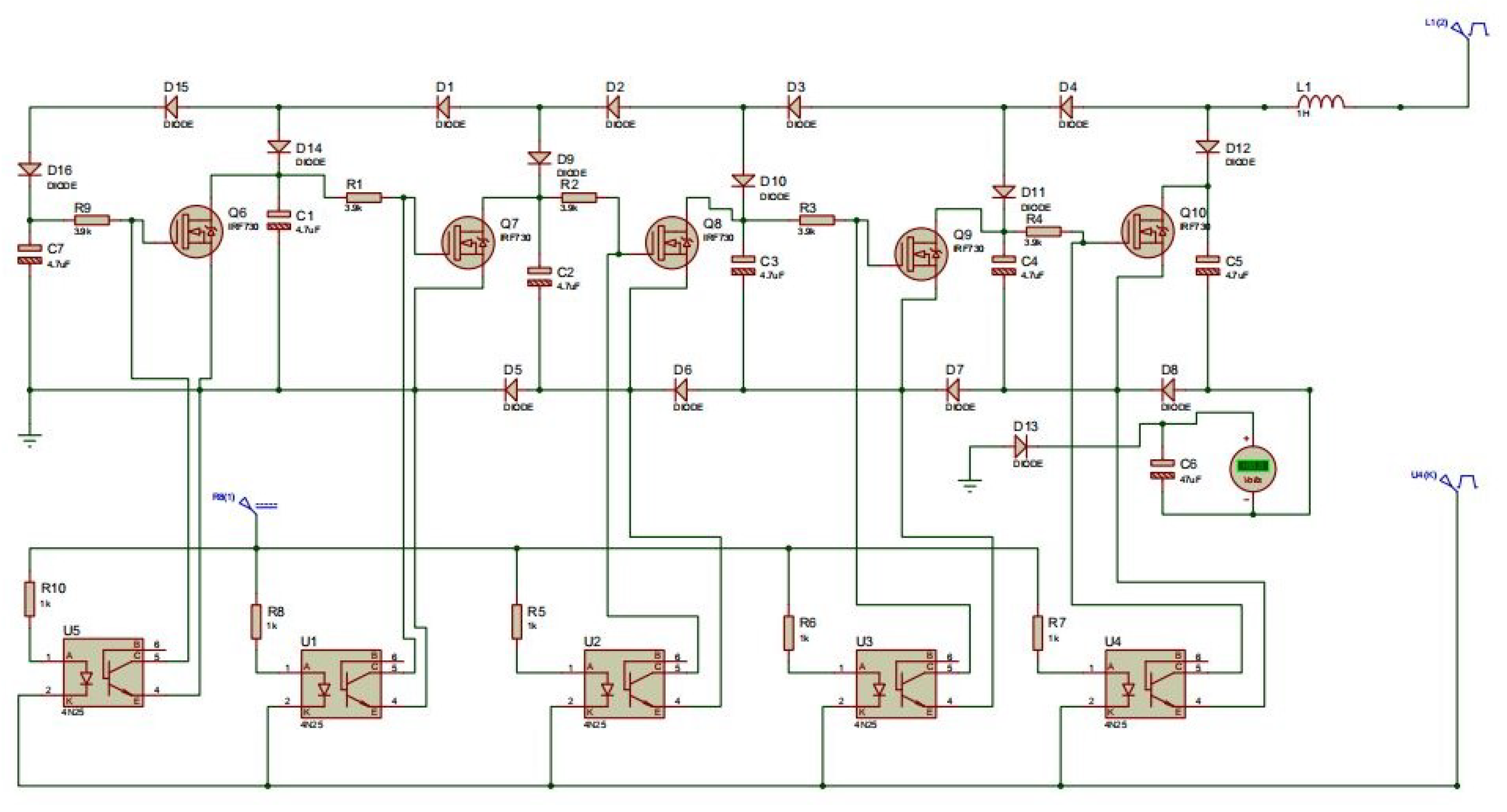
2. Materials and Methods
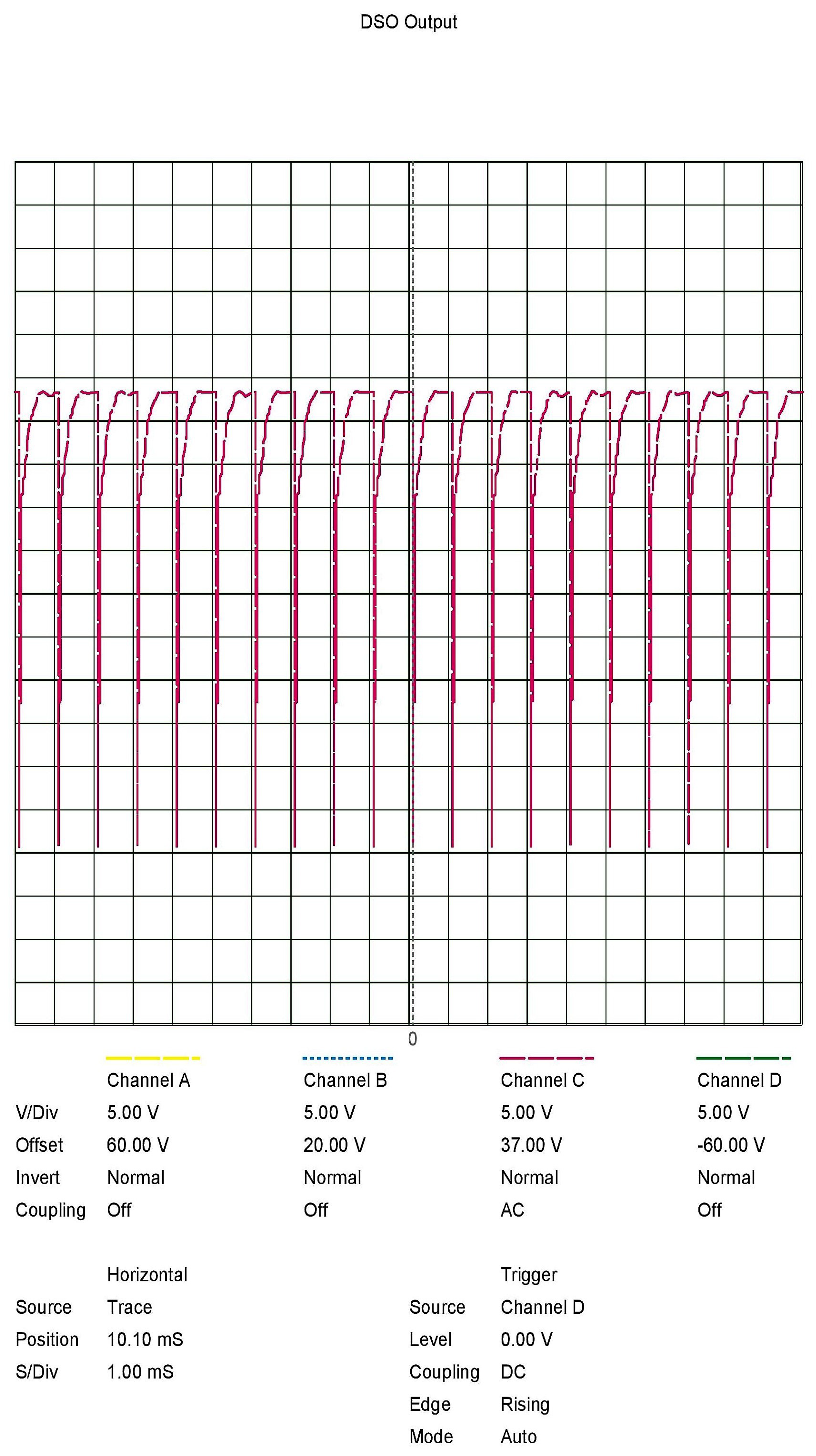
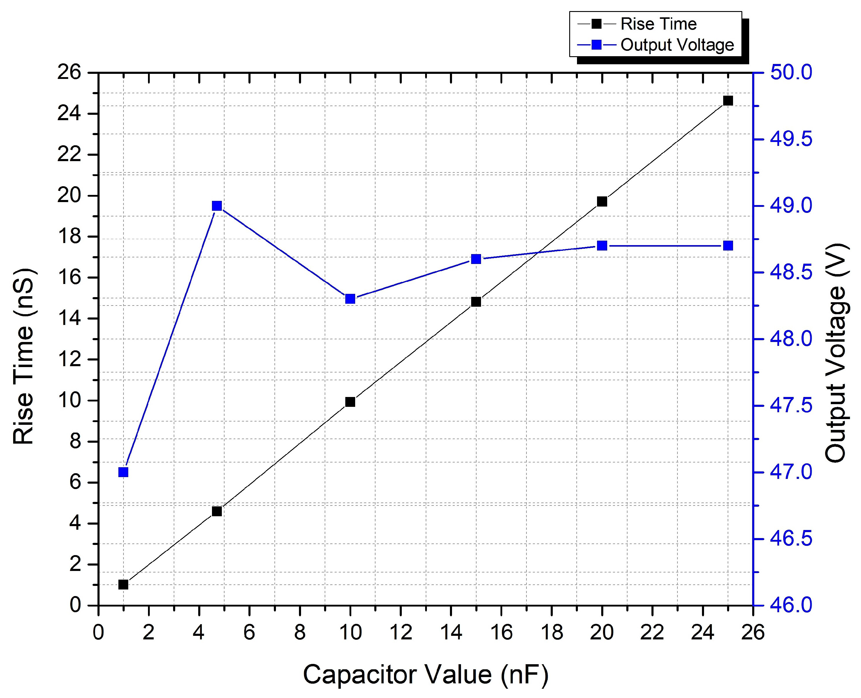
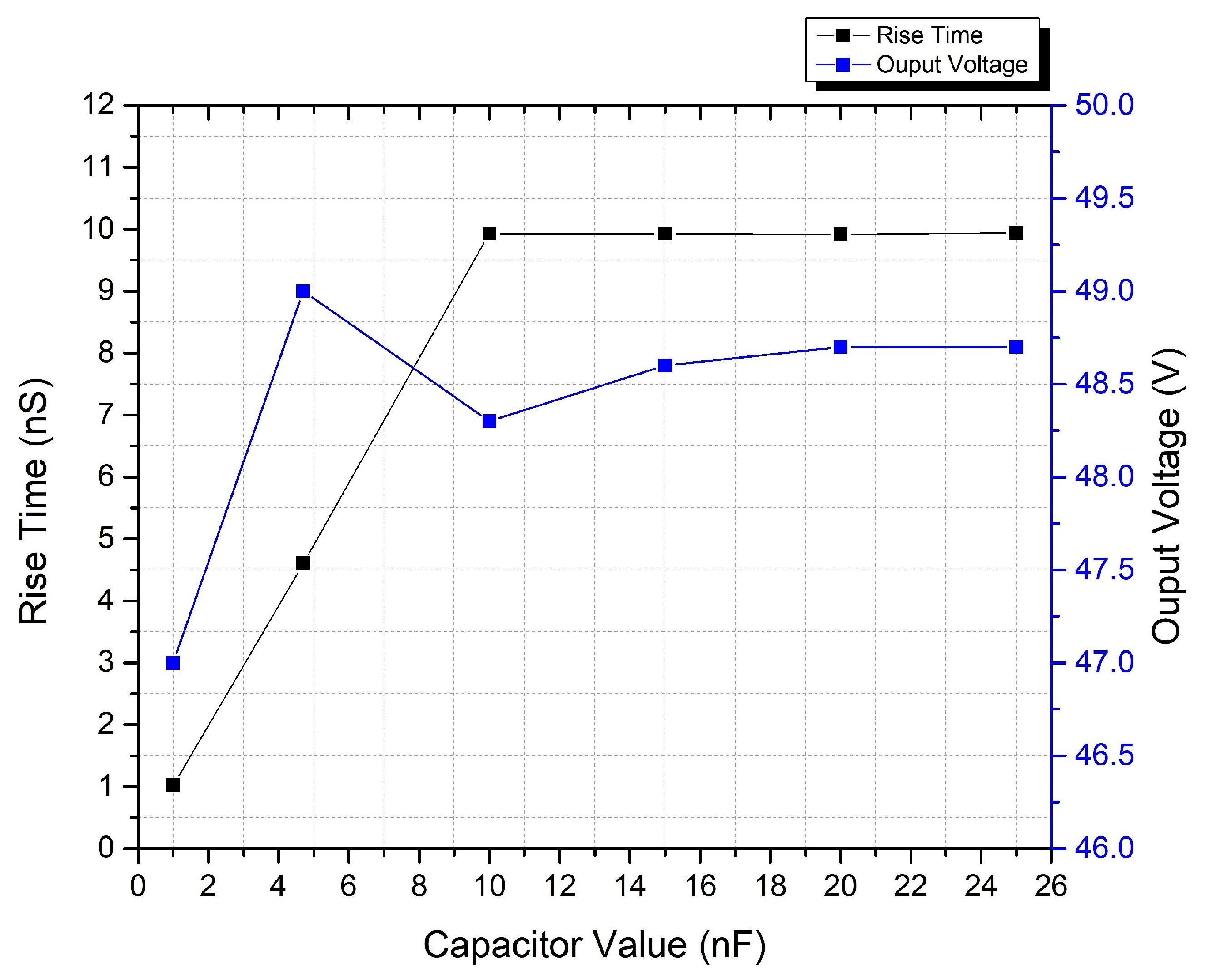
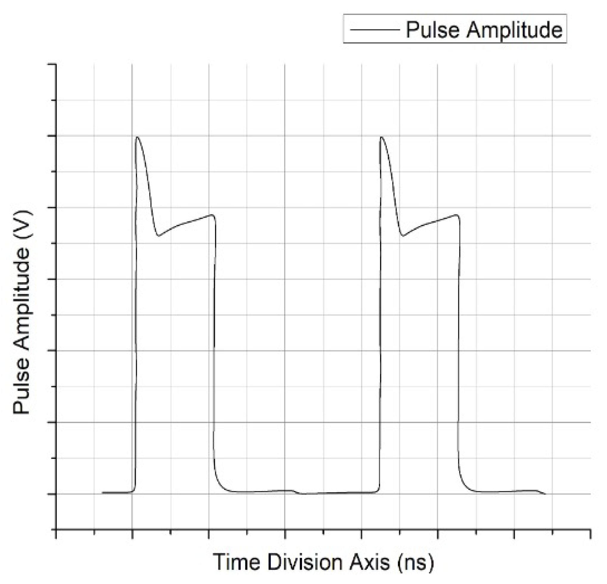
3. Results and Discussion
4. Conclusions
- One challenge was to achieve bipolar pulses with a minimum number of circuit components.
- Another challenge was the minimization of the pulse shape without minimizing the value of the capacitance, which further decreases the output voltage.
Author Contributions
Funding
Data Availability Statement
Acknowledgments
Conflicts of Interest
References
- Kotnik, T.; Rems, L.; Tarek, M.; Miklavčič, D. Membrane electroporation and electropermeabilization: Mechanisms and models. Annu. Rev. Biophys. 2019, 48, 63–91. [Google Scholar] [CrossRef] [PubMed]
- DeBruin, K.A.; Krassowska, W. Modeling electroporation in a single cell. I. Effects of field strength and rest potential. Biophys. J. 1999, 77, 1213–1224. [Google Scholar] [CrossRef] [Green Version]
- Yarmush, M.L.; Golberg, A.; Serša, G.; Kotnik, T.; Miklavčič, D. Electroporation-based technologies for medicine: Principles, applications, and challenges. Annu. Rev. Biomed. Eng. 2014, 16, 295–320. [Google Scholar] [CrossRef] [PubMed] [Green Version]
- Rubinsky, L.; Guenther, E.; Mikus, P.; Stehling, M.; Rubinsky, B. Electrolytic effects during tissue ablation by electroporation. Technol. Cancer Res. Treat. 2016, 15, NP95–NP103. [Google Scholar] [CrossRef] [PubMed] [Green Version]
- Kotnik, T.; Frey, W.; Sack, M.; Meglič, S.H.; Peterka, M.; Miklavčič, D. Electroporation-based applications in biotechnology. Trends Biotechnol. 2015, 33, 480–488. [Google Scholar] [CrossRef] [PubMed]
- Zhu, Z.; Zhang, R.; Grimi, N.; Vorobiev, E. Effects of pulsed electric field treatment on compression properties and solutes diffusion behaviors of Jerusalem artichoke. Molecules 2019, 24, 559. [Google Scholar] [CrossRef] [Green Version]
- Kranjc Brezar, S.; Kranjc, M.; Čemažar, M.; Buček, S.; Serša, G.; Miklavčič, D. Electrotransfer of siRNA to silence enhanced green fluorescent protein in tumor mediated by a high intensity pulsed electromagnetic field. Vaccines 2020, 8, 49. [Google Scholar] [CrossRef] [Green Version]
- Frandsen, S.K.; Vissing, M.; Gehl, J. A comprehensive review of calcium electroporation—A novel cancer treatment modality. Cancers 2020, 12, 290. [Google Scholar] [CrossRef] [Green Version]
- Raso, V.H.J.; Heinz, V. Pulsed Electric Fields Technology for the Food Industry; Springer: Berlin/Heidelberg, Germany, 2010. [Google Scholar]
- Chen, N.; Garner, A.L.; Chen, G.; Jing, Y.; Deng, Y.; Swanson, R.J.; Kolb, J.F.; Beebe, S.J.; Joshi, R.P.; Schoenbach, K.H. Nanosecond electric pulses penetrate the nucleus and enhance speckle formation. Biochem. Biophys. Res. Commun. 2007, 364, 220–225. [Google Scholar] [CrossRef] [Green Version]
- Kee, S.T.; Gehl, J.; Lee, E.W. Clinical Aspects of Electroporation; Springer: New York, NY, USA, 2011. [Google Scholar]
- Sharma, A.K.; Debarshi Ghosh, D.; Saluja, N.K.; Singh, T.G. A mathematical model to expedite electroporation based vaccine development for COVID-19. Bioint. Res. App. Chem. 2021, 12, 1951–1961. [Google Scholar]
- Jaeger, H.; Fauster, T.; Schottroff, F. Pulsed Electric Field Process Performance Analysis. In Pulsed Electric Fields Technology for the Food Industry; Springer: Berlin/Heidelberg, Germany, 2022; pp. 469–487. [Google Scholar]
- Furukawa, T.; Ueno, T.; Matsumura, M.; Amarasiri, M.; Sei, K. Inactivation of antibiotic resistant bacteria and their resistance genes in sewage by applying pulsed electric fields. J. Hazard. Mater. 2022, 424, 127382. [Google Scholar] [CrossRef]
- Orlacchio, R.; Carr, L.; Palego, C.; Arnaud-Cormos, D.; Leveque, P. High-voltage 10 ns delayed paired or bipolar pulses for in vitro bioelectric experiments. Bioelectrochemistry 2021, 137, 107648. [Google Scholar] [CrossRef]
- Haldiyan, A.; Ghosh, D.; Saluja, N.; Ganeshan, S.; Singh, T.G. Comparison of Nano-second and Millisecond Pulse Generators for Biological applications of Electroporation. Res. J. Pharm. Technol. 2021, 14, 2843–2851. [Google Scholar] [CrossRef]
- Elgenedy, M.A.; Darwish, A.; Ahmed, S.; Williams, B.W. A transition arm modular multilevel universal pulse-waveform generator for electroporation applications. IEEE Trans. Power Electron. 2017, 32, 8979–8991. [Google Scholar] [CrossRef] [Green Version]
- Dwarakanath, S.; Raj, P.; Praveen, K.; Saurabh, S. Generation of HVDC from Voltage Multiplier Using Marx Generator. Int. J. Adv. Res. Electr. Electron. Instrum. Eng. 2016, 5, 432–4330. [Google Scholar]
- Hosseini, S.H.; Saadatizadeh, Z.; Herís, P.C. A new multiport non-isolated bidirectional dc/dc converter with zero voltage switching and free ripple input currents. In Proceedings of the 2017 10th International Conference on Electrical and Electronics Engineering (ELECO), Bursa, Turkiye, 30 November–2 December 2017; pp. 279–284. [Google Scholar]
- Liu, S.; Zhang, J.; Zhang, Z. Review of high power compact pulse forming network-Marx generators. High Power Laser Part. Beams 2022, 34, 075001. [Google Scholar]
- Sanders, J.M.; Kuthi, A.; Wu, Y.H.; Vernier, P.T.; Gundersen, M.A. A linear, single-stage, nanosecond pulse generator for delivering intense electric fields to biological loads. IEEE Trans. Dielectr. Electr. Insul. 2009, 16, 1048–1054. [Google Scholar] [CrossRef]
- Merla, C.; El Amari, S.; Kenaan, M.; Liberti, M.; Apollonio, F.; Arnaud-Cormos, D.; Couderc, V.; Leveque, P. High-Voltage Nanosecond Pulse Generator. IEEE Trans. Microw. Theory Tech. 2010, 58, 4079–4085. [Google Scholar]
- Arnaud-Cormos, D.; Leveque, P.; Wu, Y.H.; Sanders, J.M.; Gundersen, M.A.; Vernier, T. Microchamber setup characterization for nanosecond pulsed electric field exposure. IEEE Trans. Biomed. Eng. 2011, 58, 1656–1662. [Google Scholar] [CrossRef]
- de Angelis, A.; Kolb, J.F.; Zeni, L.; Schoenbach, K.H. Kilovolt Blumlein pulse generator with variable pulse duration and polarity. Rev. Sci. Instrum. 2008, 79, 044301. [Google Scholar] [CrossRef]
- Romeo, S.; D’Avino, C.; Zeni, O.; Zeni, L. A Blumlein-type, nanosecond pulse generator with interchangeable transmission lines for bioelectrical applications. IEEE Trans. Dielectr. Electr. Insul. 2013, 20, 1224–1230. [Google Scholar] [CrossRef]
- Mehta, S.; Puri, V. 7 Level New Modified Cascade H Bridge Multilevel inverter with Modified PWM controlled technique. In Proceedings of the 2021 11th IEEE International Conference on Intelligent Data Acquisition and Advanced Computing Systems: Technology and Applications (IDAACS), Cracow, Poland, 22–25 September 2021; Volume 1, pp. 560–565. [Google Scholar]
- Reberšek, M.; Miklavčič, D. Advantages and disadvantages of different concepts of electroporation pulse generation. Automatika 2011, 52, 12–19. [Google Scholar] [CrossRef] [Green Version]
- Elgenedy, M.A.; Massoud, A.M.; Ahmed, S.; Williams, B.W.; McDonald, J.R. A modular multilevel voltage-boosting Marx pulse-waveform generator for electroporation applications. IEEE Trans. Power Electron. 2019, 34, 10575–10589. [Google Scholar] [CrossRef] [Green Version]
- Kovalchuk, B.; Kharlov, A.; Kumpyak, E.; Zherlitsyn, A. Pulse generators based on air-insulated linear-transformer-driver stages. Phys. Rev. Spec.-Top.-Accel. Beams 2013, 16, 050401. [Google Scholar] [CrossRef] [Green Version]
- Jiang, W.; Diao, W.; Wang, X. Marx generator using power mosfets. In Proceedings of the 2009 IEEE Pulsed Power Conference, Washington, DC, USA, 28 June–2 July 2009; pp. 408–410. [Google Scholar]
- MacGregor, S.; Tuema, F.; Turnbull, S.; Farish, O. The operation of repetitive high-pressure spark gap switches. J. Phys. Appl. Phys. 1993, 26, 954. [Google Scholar] [CrossRef]
- Baek, J.W.; Yoo, D.W.; Rim, G.H.; Lai, J.S. Solid state Marx generator using series-connected IGBTs. IEEE Trans. Plasma Sci. 2005, 33, 1198–1204. [Google Scholar] [CrossRef]
- Sakamoto, T.; Nami, A.; Akiyama, M.; Akiyama, H. A repetitive solid state Marx-type pulsed power generator using multistage switch-capacitor cells. IEEE Trans. Plasma Sci. 2012, 40, 2316–2321. [Google Scholar] [CrossRef]
- Redondo, L.; Silva, J.F.; Tavares, P.; Margato, E. High-voltage high-frequency Marx-bank type pulse generator using integrated power semiconductor half-bridges. In Proceedings of the 2005 European Conference on Power Electronics and Applications, Dresden, Germany, 11–14 September 2005; p. 8. [Google Scholar]
- Sarnago, H.; Burdio, J.M.; Garcia-Sanchez, T.; Mir, L.M.; Alvarez-Gariburo, I.; Lucia, O. GaN-Based Versatile Waveform Generator for Biomedical Applications of Electroporation. IEEE Access 2020, 8, 97196–97203. [Google Scholar] [CrossRef]
- Darwish, A.; Elgenedy, M.A.; Finney, S.J.; Williams, B.W.; McDonald, J.R. A step-up modular high-voltage pulse generator based on isolated input-parallel/output-series voltage-boosting modules and modular multilevel submodules. IEEE Trans. Ind. Electron. 2017, 66, 2207–2216. [Google Scholar] [CrossRef] [Green Version]
- Banaei, M.R.; Khiz, A.K. New modular high-voltage pulse generator based on SEPIC converter for electroporation applications. IET Power Electron. 2020, 13, 3072–3080. [Google Scholar] [CrossRef]
- Davies, I.; Merla, C.; Casciati, A.; Tanori, M.; Zambotti, A.; Mancuso, M.; Bishop, J.; White, M.; Palego, C.; Hancock, C. Push–pull configuration of high-power MOSFETs for generation of nanosecond pulses for electropermeabilization of cells. Int. J. Microw. Wirel. Technol. 2019, 11, 645–657. [Google Scholar] [CrossRef] [Green Version]
- Achour, Y.; Starzyński, J.; Rąbkowski, J. Modular Marx Generator Based on SiC-MOSFET Generating Adjustable Rectangular Pulses. Energies 2021, 14, 3492. [Google Scholar] [CrossRef]
- Butkus, P.; Tolvaišienė, S.; Kurčevskis, S. Validation of a SPICE model for high frequency electroporation systems. Electronics 2019, 8, 710. [Google Scholar] [CrossRef] [Green Version]
- Rodamporn, S.; Beeby, S.; Harris, N.; Brown, A.; Chad, J. Design and construction of a programmable electroporation system for biological applications. In Proceedings of the 1st Symposium Thai Biomedical Engineering, Pathumtani, Thailand, 18–19 December 2007. [Google Scholar]
- Redondo, L.; Zahyka, M.; Kandratsyeu, A. Solid-state generation of high-frequency burst of bipolar pulses for medical applications. IEEE Trans. Plasma Sci. 2019, 47, 4091–4095. [Google Scholar] [CrossRef]
- Tarigan, K.; Perangin-Angin, B.; Brahmana, K.; Manalu, A.; Sinambela, M. Simple Designed of High Voltage Pulsed Electric Field Generator Based on Fly-back Transformer. Physics 2019, 1230, 012027. [Google Scholar] [CrossRef]
- Malviya, D.; Veerachary, M. A Boost Converter-Based High-Voltage Pulsed-Power Supply. IEEE Trans. Ind. Appl. 2020, 56, 5222–5233. [Google Scholar] [CrossRef]
- Gupta, A.; Mittal, N.; Gurjar, S.; Jalan, S.K.; Talwani, S.; Mehta, S.S. Marx Generator Based High Voltage Using MOSFETs: A Review. Imp. J. Interdiscip. Res. 2017, 3, 90–94. [Google Scholar]
- Chaugule, R.V.; Ruchiharchandani; Bindu, S. Design and hardware implementation of two stage solid state bipolar Marx generator. In Proceedings of the 2016 IEEE International Conference on Recent Trends in Electronics, Information & Communication Technology (RTEICT), Bangalore, India, 17–18 May 2016; pp. 683–687. [Google Scholar]
- Saraf, G.; Bansode, A.; Khule, A.; Rangari, S.; Shinde, S. High Voltage Dc Generation using Marx Generator. IJARCEE 2017, 6, 611–645. [Google Scholar] [CrossRef]


| Ref No. | Technology Used | Quantitative Analysis | Advantage | Limitation |
|---|---|---|---|---|
| [35] | GaN | Frequency: 1 MHz Output Voltage: 2000 V | Advanced use for cancer treatments | Circuit is limited to sinusoidal waveforms, adaptation of resonant tank including frequency resolution is required |
| [36] | Multilevel Converter | Frequency: 10 KHz Output Voltage: 500 V | Step-up power electronic converter topology for generating the required HV pulses from a relatively low input voltage | This topology can only generate pulses in the KHz range. |
| [37] | SEPIC | Frequency: 50 KHz Output Voltage: 10 kV | Discontinuous conduction mode operation with continuous input current. Its fewer components is an added advantage | It can only generate pulses in the KHz range |
| [38] | MOSFET | Frequency: 50 Hz Output Voltage: 1 kV | MOSFETs are advantageous for the usage of a well-controlled electromanipulation technique, cost effective | Not suitable for high frequency range |
| [39] | SiC-MOSFET | Frequency: 10 Hz Output Voltage: 2 KV | Rectangular output pulse with a controllable amplitude, pulse width and repetition rate, a high voltage gain | Higher parasitic capacitance reduces the speed |
| [40] | MOSFET | Frequency: 10 Hz Output Voltage: 3 kV | This circuit is designed to be independent of the buffer bioimpedance | Wider range of frequencies is limited |
| [41] | MOSFET | Frequency: 4 MHz Output Voltage: 1 kV | Control module, a pulse generation circuit, and a high voltage switch using a power MOSFET | Peak transfection rate is only |
| [42] | MOSFET | Frequency: 500 KHz Output Voltage: 1 kV | It produces high-frequency bipolar high voltage pulse bursts on resistive-type loads, intended for medical applications. Used for tumor treatment | Not wuitable for high frequency range |
| [43] | Flyback Converter | Frequency: 100 KHz Output Voltage: 50 kV | Smaller space, low cost | The oscillator reaches 100 kHz, and the maximum voltage V_max pulse is approximately 52.5 kV |
| [44] | MOSFET | Frequency: 20 KHz Output Voltage: 1 kV | Cascaded Boost Converter topology | Well-synchronized driver circuit needed to trigger individual MOSFETs |
| Ref No. | Number of Stages | Switching Element | Input Voltage | Output Voltage |
|---|---|---|---|---|
| [45] | 12 | IGBT | 10 kV | 120 kV |
| [46] | 2 | Spark Gap Switches | 50 V | 92 V |
| [18] | 4 | MOSFET | 12 V | 30 V |
| [47] | 4 | IGBT | 12 V | 41.2 V |
| Proposed | 5 | MOSFET | 12 V | 49 V |
Publisher’s Note: MDPI stays neutral with regard to jurisdictional claims in published maps and institutional affiliations. |
© 2022 by the authors. Licensee MDPI, Basel, Switzerland. This article is an open access article distributed under the terms and conditions of the Creative Commons Attribution (CC BY) license (https://creativecommons.org/licenses/by/4.0/).
Share and Cite
Ganesan, S.; Ghosh, D.; Taneja, A.; Saluja, N.; Rani, S.; Singh, A.; Elkamchouchi, D.H.; Noya, I.D. A Modified Marx Generator Circuit with Enhanced Tradeoff between Voltage and Pulse Width for Electroporation Applications. Electronics 2022, 11, 2013. https://doi.org/10.3390/electronics11132013
Ganesan S, Ghosh D, Taneja A, Saluja N, Rani S, Singh A, Elkamchouchi DH, Noya ID. A Modified Marx Generator Circuit with Enhanced Tradeoff between Voltage and Pulse Width for Electroporation Applications. Electronics. 2022; 11(13):2013. https://doi.org/10.3390/electronics11132013
Chicago/Turabian StyleGanesan, Selvakumar, Debarshi Ghosh, Ashu Taneja, Nitin Saluja, Shalli Rani, Aman Singh, Dalia H. Elkamchouchi, and Irene Delgado Noya. 2022. "A Modified Marx Generator Circuit with Enhanced Tradeoff between Voltage and Pulse Width for Electroporation Applications" Electronics 11, no. 13: 2013. https://doi.org/10.3390/electronics11132013
APA StyleGanesan, S., Ghosh, D., Taneja, A., Saluja, N., Rani, S., Singh, A., Elkamchouchi, D. H., & Noya, I. D. (2022). A Modified Marx Generator Circuit with Enhanced Tradeoff between Voltage and Pulse Width for Electroporation Applications. Electronics, 11(13), 2013. https://doi.org/10.3390/electronics11132013