Review

Understanding and Controlling Band Alignment at the Metal/Germanium Interface for Future Electric Devices

by
Tomonori Nishimura
Department of Materials Engineering, School of Engineering, The University of Tokyo, Tokyo 113-8656, Japan
Electronics 2022, 11(15), 2419; https://doi.org/10.3390/electronics11152419
Submission received: 22 June 2022 / Revised: 1 August 2022 / Accepted: 1 August 2022 / Published: 3 August 2022
(This article belongs to the Special Issue Advanced CMOS Devices and Applications)

Abstract

:
Germanium (Ge) is a promising semiconductor as an alternative channel material to enhance performance in scaled silicon (Si) field-effect transistor (FET) devices. The gate stack of Ge FETs has been much improved based on extensive research thus far, demonstrating that the performance of Ge FETs is much superior to that of Si FETs in terms of the on-state current. However, to suppress the performance degradation due to parasitic contact resistance at the metal/Ge interface in advanced nodes, the reduction of the Schottky barrier height (SBH) at the metal/Ge interface is indispensable, yet the SBH at the common metal/Ge interface is difficult to control by the work function of metal due to strong Fermi level pinning (FLP) close to the valence band edge of Ge. However, the strong FLP could be alleviated by an ultrathin interface layer or a low free-electron-density metal, which makes it possible to lower the SBH for the conduction band edge of Ge to less than 0.3 eV. The FLP alleviation is reasonably understandable by weakening the intrinsic metal-induced gap states at the metal/Ge interface and might be a key solution for designing scaled Ge n-FETs.

1. Introduction

Silicon (Si) complementary metal-oxide-semiconductor (CMOS) technologies have been continuously advancing with new materials and technologies, such as high-k gate dielectrics, metal gates and strain, to overcome the physical scaling limit. Furthermore, the channel material has been replaced recently in a p-channel field effect transistor (p-FET) by silicon–germanium (SiGe), which has a smaller effective hole mass [1]. From the viewpoint of channel materials in Si CMOS technologies, since germanium (Ge) has smaller effective masses for both the electrons and hole than Si and SiGe [2] and belongs to the group XIV elements, which has a high process compatibility with Si, meaning it is an attractive candidate for an alternative channel material for further advanced nodes. Although Ge oxide has some disadvantages, such as thermodynamic instability and water solubility [3,4,5,6,7], many studies have been performed to realize high-performance Ge FETs expected from the potential of bulk Ge properties. At first, Chui [8] and Shang [9] demonstrated a high-performance Ge p-FET, which is much superior to that of Si, with the nitride passivation of the gate stack in 2002. Thereafter, by advancing the understanding of the Ge gate stack design, both the Ge n- and p-FET performance have been greatly improved [10,11,12,13,14,15,16,17,18,19,20,21,22,23]. The progress of the effective mobility improvement in inverted FET channels over the last 20 years is summarized in Figure 1. With regard to the equivalent oxide thickness (EOT) scaling in the Ge gate stack, feasibility down to approximately 0.5 nm has been demonstrated [24,25]. Additionally, Ge FETs with nanowire or gate-all-around channel structures that assume further scaling have been reported [26,27]. In the future, for designing practical Ge FETs, it is also important to consider the disadvantage of a higher dielectric constant of Ge in terms of drain-induced barrier lowering and the advantage of easy planarization by thermal annealing in various atmospheres [28,29,30] in terms of structural dispersion.
On the other hand, a typical factor that degrades performance in practically scaled FET devices is an increase in parasitic resistance. The parasitic resistance is composed of interconnecting and contact metal resistance, semiconductor resistance around the source/drain and contact resistance just at the metal/semiconductor interface; the contact resistance becomes more dominant by scaling down [31]. It is preferable to reduce the contact resistance as little as possible and below 10−9 Ωcm2 is required for advanced nodes [32].
The contact resistivity at the metal/semiconductor interface is described as [33]:
ρ exp C Φ b N ,
where Φ b and N are the Schottky barrier height at the interface and the density of the electrically activated impurities in the semiconductor, respectively. Therefore, to reduce the contact resistivity, a decrease in the Schottky barrier height and an increase in the activated impurity density are required based on the precise control of the Schottky barrier height and impurity activation and diffusion. Both are tough challenges for Ge CMOS, but this paper addresses the former.

2. Fermi Level Pinning at the Metal/Ge Interface

The Schottky barrier height is one of the band alignment parameters at the metal/semiconductor interface and the barrier for the conduction band ( Φ b n ) at the ideal interface with no charge transfer is described as:
Φ b n = Φ m χ ,
where Φ m and χ are vacuum work functions of the metal and electron affinity of the semiconductor, respectively. This case is also called the Schottky limit and Φ b n decreases (increased) as much as the decrease (increase) of Φ m (Figure 2a).
However, in most cases of actual metal/semiconductor interfaces, Φ b n is not as sensitive to Φ m . It is known as Fermi level pinning (FLP) and is generally described as a charge transfer between the metal and semiconductor through the interface states ( D i t ) in the band gap of the semiconductor [34] (Figure 2b). Assuming a constant D i t in the energy gap of the semiconductor, the band alignment is described as:
Φ b n = S Φ m χ + 1 S Φ C N L ,   S = 1 1 + q δ D i t ε ,
where q , δ and ε are the elementary charge, dipole length and dielectric constant at the interface, respectively. Φ C N L is the charge neutrality level of the semiconductor at the interface from the conduction band edge of the semiconductor. According to the equation, S is a parameter of sensitivity to Φ m and takes a value between 0 and 1. S and Φ C N L can be regarded as the FLP strength and FLP energy level. When S is 0, the Schottky barrier height becomes completely constant irrespective of Φ m . This case corresponds to the Bardeen limit.
Next, we discuss the relationship between the vacuum work function of the metal and Schottky barrier height at the metal/Ge interface. The systematic trend was first reported by Thanailakis in 1973 [35]. After that, analyses focusing on FLP were reported by Marshall [36], Dimoulas [37] and Nishimura [38,39]. The relationships between the Schottky barrier height at metal/n-Ge(100) and the vacuum work function of metal are summarized in Figure 3a. The vacuum work function of metals is found in references [40,41]. In three recent reports, the Fermi level at the metal/Ge(100) interface is close to the valence band edge of Ge and is little dependent on the vacuum work function of the metal and a large Schottky barrier comparable to the band gap of Ge is formed on n-Ge. The FLP strength of the S parameter at the metal/Ge(100) interface is evaluated from the slope in Figure 2a to be 0.02–0.05, which is much less than that at the typical metal/Si interface (~0.3) [34]. The FLP energy level of Φ C N L at the interface is estimated from the intersection of the fitted data line with the Schottky limit line in Figure 2a to be 0.49–0.58 eV. Both the S parameter and Φ C N L are almost the same among the results in recent studies [36,37,38,39].
From the correlation between the S parameter and D i t shown in Equation (3), the FLP strength can be quantitatively considered as the interface state density for the sake of convenience, irrespective of the mechanism of FLP. For example, assuming a δ of 0.5 nm and ε of 10 ε 0 , the S parameter of 0.02 at the metal/Ge(100) interface is equivalent to a D i t of 5 × 10¹⁴ states/cm3/eV. It implies that the interface might be electrically very poor, considering that the atomic density on the Ge(100) surface is almost 6 × 10¹⁴/cm2.
The band alignment shown in Figure 2a was determined from the electric characteristics (such as I-V or C-V characteristics) of metal/n-Ge(100) junctions (typical I-V characteristics are shown in Figure 3b). On the other hand, it is difficult to determine from metal/p-Ge(100) junctions. The Schottky barrier height for the valence band edge of Ge at metal/p-Ge(100) is very low and ohmic contact is easily formed on the junction at room temperature. This is a large advantage for p-type Ge devices in terms of choice for the contact metal, but a critical disadvantage for n-type Ge devices. To reduce the contact resistance at the metal/n-Ge interface towards the realization of practical n-type Ge devices, the strong FLP close to the valence band edge must be overcome based on an understanding of its FLP mechanism.

3. Dominant FLP Mechanism at the Metal/Ge Interface

First, typical FLP mechanisms discussed for various metal/semiconductor interfaces are reviewed, before a discussion of the dominant FLP mechanism at the metal/Ge interface. FLP mechanisms can be categorized into intrinsic or extrinsic mechanisms. Here, “intrinsic FLP” means that the FLP is caused by an intrinsic charge transfer due to the metal/semiconductor interface formation itself, while “extrinsic FLP” means that the FLP is caused by a charge transfer through the actual interface states, such as defects introduced by the interface formation process. Metal-induced gap states (MIGS) [42,43,44,45,46] and chemical bond models [47,48] are typical intrinsic FLP mechanisms. In the MIGS model, a charge transfer is caused by a wave function tailing from the metal into the finite semiconductor band gap. In the chemical bond model, it is through local chemical bonding between metal and semiconductor atoms, considering an energy gain in the charge transfer against the band gap of the semiconductor. On the other hand, the unified defect model (UDM) [49,50] and disorder-induced gap states (DIGS) [51,52] are typical extrinsic FLP mechanisms. The UDM has been discussed regarding the metal/III-V semiconductor interfaces and is based on the formation of a universal defect energy level irrespective of the adsorbed element on the semiconductor. In the DIGS model, the interface state density related to the FLP strength is characterized by the strain and distortion of bonds, defects and dangling bond densities. The FLP energy level is determined by the sp3 hybrid orbital energy, which is universally located at approximately 5 eV from the vacuum level in diamond- and zinc-blend-type semiconductors.
However, it is difficult to identify a dominant FLP mechanism at the metal/Ge interface from the FLP strength, as follows. Since 1970, it has been implied that pure covalent bonding semiconductors such as Ge and Si exhibit strong FLP [53]. The FLP strength of various semiconductors has been systematically investigated and the correlation of FLP strength with the ionic bond character in semiconductors has been discussed from the viewpoint of surface states, which is based on the relationship between the ionic bonding character and electronic structure modulation. In the previously mentioned intrinsic MIGS and chemical bond model, FLP strength is primarily characterized by the electronic gap of the semiconductor because the charge transfers in MIGS and the chemical bond model are dependent on the decay of wave function tailing in the semiconductor and the energy gain of the charge transfer to the valence band or conduction band of the semiconductor. Considering the narrow band gap of Ge (0.66 eV at room temperature), it seems reasonable that strong FLP occurs at the metal/Ge interface. In the UDM and DIGS, simply saying, the FLP strength is determined by the actual interface states density. For example, the surface cleaning method before metal deposition and the reduction of metal diffusion into the semiconductor inside by cooling during metal deposition may be effective in reducing the interface state density and weakening the FLP at the metal/6H-SiC [54] and metal/GaAs [55] interfaces, while the alleviation of FLP at the metal/Ge interface by appropriate surface treatment has not been reported. However, the narrow band gap of Ge indirectly implies that the bond structure in the Ge crystals is easily broken and so a high density of interface states may possibly be formed, which implies that the extrinsic FLP mechanism causes the strong FLP of Ge.
It is also difficult to identify the dominant FLP mechanism from the viewpoint of the FLP energy level. The experimentally determined effective charge neutrality level is close to the valence band edge of Ge. In intrinsic mechanisms, the MIGS describes the FLP energy level as an energy level that corresponds to the charge neutrality level of the bulk semiconductor, where the dominance of the conduction band character and valence band character is changed in the band gap. (It is a branch point in a one-dimensional system.) The charge neutrality level Φ C N L of Ge is calculated to be 0.48 [44] and 0.63 [56]. On the other hand, in extrinsic mechanisms, the DIGS model describes the FLP energy of Ge. The energy in the DIGS model is the sp3 hybrid orbital energy, which is the same as the charge neutrality level of the bulk semiconductor [51]. This result is also consistent with the fact that vacancies in Ge work as acceptors [57] and that defective Ge exhibits p-type characteristics [58,59].
Therefore, another approach is needed to understand the dominant FLP mechanism. Here, we present an interesting result of comparing Ge and Si with SiGe [60]. A key property of SiGe is the complete solid solution of Si and Ge. Therefore, SiGe includes natural bond distortion and disordering even in perfect crystals. Moreover, SiGe used in the experiment is not a single crystal substrate, but epitaxially grown on a Si substrate, which suggests that SiGe includes extrinsic defects, dislocations and strain. These structural disorders are detected, for example, as the broadening of the diffraction peak in the XRD measurement. On the other hand, the band gap of SiGe monotonically increases with the decreasing Ge ratio. Therefore, the band gap becomes simply wider in the order of Ge, SiGe and Si. Therefore, the FLP mechanism, which dominantly characterizes the metal/Ge interface, could be speculated by which metal/Ge and metal/SiGe interfaces exhibit a stronger FLP. To analyze the band alignment at the metal/SiGe interface, the Schottky barrier height is estimated from the rectified I-V characteristics of metal/n-SiGe(100) diodes, as shown in Figure 4a. The saturation current density at the metal/SiGe junction is obviously metal dependent compared with that at the metal/Ge junction shown in Figure 2b. Figure 4b shows the relationship between the band gap, crystallinity and FLP strength of Ge, SiGe and Si. The S parameter for the metal/SiGe(100) interface is estimated to be 0.07. This value is less than that for the metal/Si (100) of 0.16, which is consistent with reports from Archer [61], but obviously more than that for the metal/Ge(100) of 0.02. The D i t of 1.4 × 10¹³/cm2/eV, which corresponds to the S parameter for SiGe, is much lower than that for Ge, even though SiGe has various structural disorders. These experimental facts imply that the FLP of Ge may be dominantly characterized by an intrinsic mechanism. Furthermore, the band alignment at the metal/Ge interface does not seem sensitive to the surface orientation of Ge [39], which suggests that local structural characteristics such as bonding at the interface do not strongly characterize the band alignment. In other words, the FLP seems to be characterized by bulk Ge characteristics. This means that MIGS seems to be the most reasonable FLP mechanism to describe the FLP at the metal/Ge interface. If the strong FLP was extrinsic, the passivation and/or generation of extrinsic interface states should be carefully considered. However, it appears to be intrinsic so that some sort of breakthrough is needed.

4. FLP Alleviation by Ultrathin Interface Layer

In this chapter, focusing on the fact that such a strong FLP does not occur at a typical metal/insulator/Ge interface, an approach to alleviate the strong FLP at the metal/Ge interface is discussed. As mentioned in the introduction, various Ge gate stacks have been analyzed by C-V characteristics to improve the performance of Ge FETs [8,9,10,11,12,13,14,15,16,17,18,19,20,21,22,23]. In these C-V characteristics, the accumulation, depletion and inversion of the Ge layer are distinctly observed, which indicates that the surface potential of Ge is modulatable; in other words, the insulator/Ge interface is not strongly pinned as with the metal/Ge interface. On the other hand, the flat band voltage of the Ge Metal/Insulator/Semiconductor (MIS) capacitor obviously depends on the vacuum work function of the metal [62], which also suggests that a strong FLP does not occur at the metal/insulator interface. Therefore, our interest arising from the band alignment of the Ge MIS interfaces was how the FLP-free Ge MIS interfaces behave after extremely thinning the insulator. In the best case, we hoped that enough current could flow in the on state at the FLP-free MIS junction.
We selected GeO2, which is an oxide of the substrate, as an ultrathin interface insulator to simplify the system. Additionally, GeO2 could form an electrically better interface with Ge by the suppression of GeO desorption compared with other insulators [63,64]. Al was chosen as an electrode metal with a low vacuum work function to form low and high Schottky barrier heights for n- and p-Ge at the FLP weakened interface, respectively. Figure 5a shows typical I-V characteristics of Al/Ge(100) diodes with and without an ultrathin GeO2 layer. Surprisingly, the Al/n-Ge diode characteristics change from Schottky to ohmic by inserting a GeO2 layer, whereas the Al/p-Ge diode characteristics change from ohmic to Schottky [65]. This is definitely understandable by a shift of the Fermi level at the interface from the valence band edge of Ge to the near conduction band edge. The ultrathin GeO2 interface layer between the Al and Ge substrates is also confirmed by the cross-sectional TEM image shown in Figure 5b.
Furthermore, the correlation between the Schottky barrier height at metal/ultrathin GeO2/Ge exhibits an obvious vacuum work function dependence, as shown in Figure 6. The vacuum work function dependence of the Schottky barrier height indicates that the ultrathin insulator surely has a role in alleviating the FLP and that the Schottky–ohmic reversal of Al/ultrathin GeO2/Ge diodes shown in Figure 4a is not caused only by the pinning level shift. As summarized in Figure 7a,b, Schottky barrier height modulation and FLP alleviation have been observed by Al2O3 [66,67], TiO2 [68,69,70], MgO [71,72], GeON [73], TiON [74], GeN [75] and SiN [76], in addition to GeO2 [65,68]. These experimental results imply that the FLP alleviation by inserting an ultrathin insulator into the metal/Ge interface is attributed to the insulating property of the interface layer or interface passivation by the oxygen or nitrogen included in the interface layer.
Next, from the viewpoint of the role of insulator in FLP alleviation, the dominant FLP mechanism at metal/Ge is considered again. The FLP alleviation by ultrathin insulators is explainable in various models, as follows. In the intrinsic MIGS, the wave function tailing to the semiconductor decays due to the wide energy gap and physical distance of the interfacial layer. In the intrinsic chemical bond model, the energy gain in the charge transfer with metal will be reduced by replacing the semiconductor with a wide gap insulator. In extrinsic models, nonideal semiconductor structures, such as defects or dangling bonds, resulting in interface states are passivated by oxygen or nitrogen. However, it is noted that the role of the interface layer in each model is different. It is expected that intrinsic MIGS is gradually weakened with an increasing insulator thickness as a result of the thickness effect, whereas the extrinsic FLP mechanisms are immediately suppressed by forming an insulator/Ge interface by the interface passivation effect. Hence, from an impact of interlayer thickness on the FLP strength, the appropriate mechanism to describe the FLP at the metal/Ge interface could be speculated from another aspect.
Figure 8a shows the Schottky barrier height at the metal (Al, Cu and Au)/GeO2/Ge interface as a function of GeO2 thickness. The Schottky barrier heights in the figure are evaluated from the saturation current density in I-V characteristics measured at room temperature and the Richardson constant, without any correction for the tunnel resistance [68]. However, it is obvious that the Schottky barrier height for the conduction band edge of Ge at the Al (low work function metal) and Au (high work function metal) contact interfaces gradually decreased and increased, respectively, with increasing GeO2 thickness. Although it is difficult to exactly discuss the FLP strength from the few kinds of metals with different vacuum work functions, the S parameter evaluated from the three kinds of metal gradually increases with GeO2 thickness, as shown in Figure 8b. Gradual FLP weakening with an increasing interface layer thickness is also observed at the metal/Si interface [68]. Although, Schottky barrier height modulation at the metal/Si interface by an ultrathin insulator as a concept of MIGS suppression had been proposed by Connelly [77] before the reports of these studies, which are focused on Ge, and these results suggest that the thickness effect of the insulator results in FLP alleviation and qualitatively support that MIGS is the dominant FLP mechanism both at the metal/Ge and /Si interfaces. On the other hand, here, it is assumed that MIGS and other FLP mechanisms work independently. It is, however, reported that intrinsic MIGS reduces defect formation energy based on first-principles calculations [78] and that Si bond breaking by contact with metal has been observed [79]. Therefore, to further understand FLP alleviation, more quantitative analysis, including the secondary effect of MIGS, might be necessary.

5. FLP Alleviation by Low Free-Electron-Density Metal

From the viewpoint of reducing contact resistance, direct metal/Ge contact is preferable to metal/ultrathin insulator/Ge contact if FLP alleviation is possible at the direct interface. In this section, how to alleviate the FLP at a direct metal/Ge interface is discussed, assuming the MIGS dominant interface. The presumption is that the FLP strength caused by MIGS is characterized by the electronic structure of the semiconductor, such as the band gap [45,46], since it is related to the coefficient of wave function decay in the semiconductor. However, considering that the wave function which decays in the semiconductor is correlated with that in the metal, it is expected that the strength of MIGS could also be modulated from the metal side as follows.
In the MIGS model, the interface dipole, which causes FLP, is described as a result of the wave function tailing from the metal. Therefore, the assumption is that such a dipole is also formed at other interfaces. For example, even at the metal/vacuum interface, as the simplest case, the wave function tailing from the metal also occurs through a finite energy barrier between the Fermi level in the metal and the vacuum level, which would result in interface dipole formation. Interestingly, the dipole formed at the metal/vacuum interface corresponds to a part of the vacuum work function of the metal. Lang calculated the vacuum work function of metal with a simple Jellium model [80,81]. In that model, the vacuum work function is composed of a bulk term and surface term; the former term includes the interaction energy and kinetic energy in the bulk and the latter corresponds to the surface dipole due to wave function tailing from the metal to the vacuum. The model is significantly simple, but the result well describes the vacuum work function of simple metals such as alkaline and alkali-earth metals. Here, it is a notable point that the surface term is reduced with a decreasing free-electron density in the metal, which indicates that the metal/vacuum interface dipole caused by wave function tailing is reduced. Therefore, MIGS at the metal/semiconductor, which is described as a dipole caused by wave function tailing, could be weakened by the decreasing free-electron density in the metal based on the similarity of the physical description of the “surface term of the vacuum work function” and “MIGS”.
The free-electron density in single-element metals commonly used to analyze FLP at the metal/semiconductor interface is approximately 1022–1023/cm3 [82], whereas, for example, in compound metals such as silicide, it is one digit less, approximately 1021/cm3 [83]. The free-electron density in germanide, which is a compound of metal and Ge, is expected to be almost the same as that in silicide and the free carrier densities in Y-germanide and Gd-germanide were evaluated to be 7 × 10¹⁹ and 9 × 10¹⁹/cm3, respectively, by Hall effect measurements. Considering the previously mentioned analogy between MIGS and the surface term of the vacuum work function, the FLP at the germanide/Ge interface is expected to be weaker than that at the single-element metal/Ge interface.
Germanide/n-Ge(100) diodes show rectified I-V characteristics (Figure 9a), but the saturation current densities seem to have a strong metal dependence compared with those of single-element metals/n-Ge diodes (shown in Figure 2b), although the swept range of the vacuum work function of germanide might be much narrower than that of single-element metals due to compound formation with Ge. The relationship between the vacuum work function of the metal and the Schottky barrier height at the metal/Ge interface is shown in Figure 9b. Here, the work function of crystallized germanide is assumed from the metal–Ge composition ratio in its crystal structure, the group electronegativity [84] and the relationship between the electronegativity and vacuum work function [85]. The FLP at the germanide/Ge interface is weaker, as expected, and the S parameter for the germanide/Ge(100) interface is estimated to be 0.17, which is much larger than that for the single-element metal/Ge(100) interface. Additionally, deviation from the strong FLP trend at the single-element metal/Ge interface has also been reported at the YbGex/Ge [86], epitaxial Mn5Ge3/Ge(111) [87], epitaxial HfGe2/Ge(100) [88] and epitaxial Fe3Si/Ge(111) [89] interfaces. These results seem reasonably understandable by the weakening of MIGS, even though interface epitaxiality may sufficiently affect the band alignment in detail. Furthermore, in the case of the metal/Si interface, FLP at the silicide/Si interface is also much weaker than that at the single-element metal/Si interface [90,91]. In addition to interfacial layer insertion, a low free-electron-density metal is also effective in alleviating the FLP at the metal/Si interface, which suggests that MIGS might also describe the FLP at the metal/Si interface well.
At the metal/semiconductor interface with strong MIGS, the band alignment is dominantly determined by the charge neutrality level, which is characterized by the bulk properties of the semiconductor. However, by weakening MIGS at the interface, the assumption is that other FLP mechanisms or interface structures possibly affect band alignment. Actually, the Schottky barrier height at the germanide/Ge interface has a noticeable surface orientation dependence [92], as shown in Figure 10a. It was also demonstrated that ohmic contact can be formed for n-Ge at room temperature without the heavy doping of impurities by employing an appropriate metal and surface orientation of Ge, although a direct metal/Ge interface is formed (Figure 10b). However, here, care is taken that not only Ge surface orientation, but also other properties, such as germanide orientation, might be different for each Ge orientation because the germanide/Ge interface was formed by thermal reaction of the elemental metal/Ge interface.
The difference between single-element metals and compound metals such as silicide and germanide on FLP at epitaxial metal/Ge and /Si interfaces has been discussed based on first principle calculations [93]. According to the calculations, the Fermi level at the single-element metal/semiconductor interface is determined by MIGS around the dangling bond states of the semiconductor, while that at silicide/Si or germanide/Ge is determined by that of the metal, which provides the difference in FLP strength. The calculated Si and Ge surface orientation dependence on the band alignment is not completely consistent with the experimental results [92], but the difference in the Schottky barrier height at the A- and B-type epitaxial NiSi2/Si interfaces [94] is successfully reproduced. This suggests a key to further understanding the impact of the microscopic interface structure on band alignment from the viewpoint of local atomic configuration.
On the other hand, as previously implied, the interface fabrication process is different between the germanide/Ge and single-element metal/Ge interfaces. The germanide/Ge interface is generally formed by a thermal reaction, while the single-element metal/Ge interface is by deposition. To purely focus on the impact of the low-electron-density metal on the FLP, an example of band alignment at a low free carrier density metal/Ge interface formed by deposition is discussed. Bismuth (Bi) is a famous semimetal and its carrier density is approximately 1017/cm3, which is much less than that of common single-element metals [95]. Bi can be thermally evaporated in a vacuum chamber in the same manner as other single-element metals. There is no choice to pick up various semimetals with different vacuum work functions, such as single-element metals, but the vacuum work function of Bi is fortunately 4.22 eV [40]. It is energetically far from the FLP energy level of Ge of approximately 4.6 eV from the vacuum level, so the alleviation of the strong FLP is detectable as an obvious modulation of the Schottky barrier height. Additionally, Bi cannot form a compound (germanide) with Ge [96], which means that the possibility of band alignment modulation by Bi-germanide formation can be ruled out. As shown in Figure 11, Bi/n-Ge diodes still show rectified I-V characteristics, but the off-state current density is very high compared with the single-element metal cases. Moreover, the I-V characteristics of Bi/p-Ge(100) diodes are definitely rectified. In the relationship between the vacuum work function of metal and the Schottky barrier height at the metal/Ge interface, Bi obviously deviates from the trend of strong FLP observed at the single-element metal/Ge interface and is close to the Schottky limit [97], which suggests that MIGS at the Bi/Ge interface is efficiently suppressed. The FLP-free interface is also obtained at the Bi/Si interface [97] and the FLP-free Bi/2D semiconductor interface has also been reported [98]. Furthermore, the Schottky barrier height at the Bi/Ge interface is obviously changed within 0.05 eV, depending on the surface orientation of Ge. Although the details of the surface orientation dependence have yet to be clarified, considering the polycrystallinity of Bi on the Ge substrate, the impact of Ge surface orientation on the band alignment might directly appear in this system.
As denoted above, the low-electron-density metal effect on the FLP supports that MIGS is the most reasonable mechanism to describe the strong FLP. Certain metals (e.g., WSix [99], a-TiNGe [100], TaN [101,102], Sn [103], graphene [104] and CNT [105]) show deviation from the strong FLP trend at the single-element metal/Ge interface, as summarized in Figure 12, but these results also seem understandable as MIGS reduction from the metal side, similar to germanide and Bi. Further clarification about the correlation between the interface structure and band alignment at low-electron-density metal/Ge and /Si are current big challenges to build a guideline to precisely control the band alignment at direct metal/Ge and /Si interfaces.

6. Reduction of Contact Resistivity

Finally, the reduction of contact resistivity at the metal/Ge interface is discussed. The contact resistivity at the MIGS-effective metal/Si interface is fully described based on the field emission and thermionic-field emission current [106]. Therefore, here, the contact resistivity at the metal/Ge interface is discussed based on the band alignment (Schottky barrier height), although it has been reported that MIGS might affect the electronic structure of the semiconductors at the metal/2D semiconductor interface [107]. As mentioned in the previous sections, the ultrathin insulator layer at the metal/Ge interface enhances the controllability of the Schottky barrier height, but adds series resistance due to the tunnel barrier. Hence, for the ohmic contact formation to lightly doped semiconductors with a lower contact resistance, the best thickness can be determined based on the balance between FLP alleviation and insulator resistance. Since the tunnel resistance is decreased by reducing the potential barrier of the insulator, it is better for the reduction of contact resistivity to select an insulator with a small band offset between the insulator and semiconductor. For contact with the conduction band of Ge, TiO2 [69], ZnO [108] and WSix [99] have been proposed with the demonstration of FLP alleviation.
For contact in aggressively scaled n-type Ge devices, tunnel resistance caused by both the interface insulator layer and semiconductor depletion layer must be considered because of heavily doping of impurities in Ge. In the case of contact for the conduction band of Si with doping over 1020/cm3, it is expected that even TiO2 might lose the advantage of a small band offset due to an increasing tunnel distance in TiO2 [109]. As a solution, a more conductive interface layer with a low band offset and heavy doping has been proposed. For example, Al-doped ZnO and indium tin oxide (ITO) might be possible candidates for contact with the conduction band of Ge. Low contact resistivity for lightly doped n-Ge has been obtained experimentally [110], calculating that the resistivity would be reduced to approximately 10−9 Ωcm2 [111].
Furthermore, a low-electron-density metal does not have tunnel resistance due to its metallic property. The contact resistivity at the NiGe/n-Ge interface [112,113] still exhibits high resistivity. However, the speculation is that other metals, such as rare-earth germanide, which forms a low Schottky barrier height, could significantly reduce the resistivity. Although the bulk resistivity of rare-earth germanide is slightly high (~10−4 Ωcm), rare-earth germanide can be thinned down to 5 nm while maintaining a low Schottky barrier height of 0.3 eV [114]. This result suggests that the total contact resistivity, which includes the bulk resistivity of germanide, is possibly reduced below 10−9 Ωcm2 when the tunneling effective mass of an electron of 0.12 m0 [115] and the high doping density up to ~1020/cm3 are assumed. The contact resistivities at various metal/n-Ge interfaces, including other interface layers [116,117], are summarized in Figure 13.

7. Conclusions

To realize scaled Ge FET devices, the reduction of contact resistivity is indispensable. However, it was found that the band alignment at common metal/Ge interfaces is far from the Schottky limit and a high Schottky barrier height for the conduction band edge of Ge is formed irrespective of the metal work function. This is described as a strong FLP close to the valence band edge of Ge. Therefore, this is a major hurdle to achieve high-performance Ge n-channel devices, including FETs.
The origin of strong FLP is expected to be so-called MIGS, based on the comparison of FLP strength between the metal/Ge interface and metal/SiGe interface focusing on intrinsic and extrinsic structural disorder in SiGe. This MIGS dominant FLP at the metal/Ge interface is also reasonably supported by the ultrathin insulator effect and low free-electron-density metal effect, as later denoted.
To alleviate the strong FLP at the metal/Ge interface, two kinds of approaches are demonstrated. One is the insertion of an ultrathin interface layer at the metal/Ge interface. This approach is motivated by research on the FLP free-metal/insulator/Ge gate stacks. The inserted interface layer has a role in reducing the tailing of the wave function into the band gap of the semiconductor by decaying in the layer. As experimental facts, various interlayers exhibit FLP alleviation and the FLP alleviation is enhanced with an increasing interface layer thickness. The other approach is applying a low free-electron metal as a contact metal. The analogy between the surface term of the vacuum work function of metal in a simple Jellium model and MIGS at the metal/semiconductor interface implies that the strength of MIGS is also characterized by the metal and MIGS can be reduced by decreasing the free-electron density in metal, which is a viewpoint different from before. Both the FLP alleviation at the germanides/Ge interfaces and the deviation from the strong FLP trend at some special metal/Ge interfaces are reasonably understandable based on the character of MIGS.
By further understanding the metal/Ge interface, the band alignment at the metal/Ge interface becomes more controllable. For this situation, assuming the well-controlled activation and diffusion of impurities in Ge, contact resistivity of less than 10−9 Ωcm2 seems achievable. Therefore, to realize practical Ge n-channel devices in future nodes, further refined guidelines for interface design to reduce contact resistivity based on a further understanding of band alignment at the MIGS-weakened metal/Ge interface are desired.

Funding

This work was partially supported by JST CREST (JPMJCR0843), Harmonic Ito Foundation and JSPS KAKENHI Grant Numbers 22760244, 25420320, 17K06374 and 22K04212.

Acknowledgments

The author is grateful to Akira Toriumi and Kosuke Nagashio for fruitful discussions.

Conflicts of Interest

The author declares no conflict of interest.

References

  1. Yeap, G.; Lin, S.S.; Chen, Y.M.; Shang, H.L.; Wang, P.W.; Lin, H.C.; Peng, Y.C.; Sheu, J.Y.; Wang, M.; Chen, X.; et al. 5nm CMOS Production Technology Platform Featuring Full-Fledged EUV, and High Mobility Channel FinFETs with Densest 0.021µm2 SRAM Cells for Mobile SoC and High Performance Computing Applications. In Proceedings of the 2019 IEEE International Electron Devices Meeting (IEDM), San Francisco, CA, USA, 7–11 December 2019; pp. 36.7.1–36.7.4. [Google Scholar]
  2. Fischetti, M.V.; Laux, S.E. Band Structure, Deformation Potentials, and Carrier Mobility in Strained Si, Ge, and SiGe Alloys. J. Appl. Phys. 1996, 80, 2234–2252. [Google Scholar] [CrossRef]
  3. Nagashio, K.; Lee, C.H.; Nishimura, T.; Toriumi, A. Thermodynamics and Kinetics for Suppression of GeO Desorption by High Pressure Oxidation of Ge. MRS Proc. 2009, 1155, C06-02. [Google Scholar] [CrossRef]
  4. Kita, K.; Suzuki, S.; Nomura, H.; Takahashi, T.; Nishimura, T.; Toriumi, A. Direct Evidence of GeO Volatilization from GeO2/Ge and Impact of Its Suppression on GeO2/Ge Metal–Insulator–Semiconductor Characteristics. Jpn. J. Appl. Phys. 2008, 47, 2349–2353. [Google Scholar] [CrossRef]
  5. Wang, S.K.; Kita, K.; Lee, C.H.; Tabata, T.; Nishimura, T.; Nagashio, K.; Toriumi, A. Desorption Kinetics of GeO from GeO2/Ge Structure. J. Appl. Phys. 2010, 108, 054104. [Google Scholar] [CrossRef]
  6. Wang, S.K.; Kita, K.; Nishimura, T.; Nagashio, K.; Toriumi, A. Kinetic Effects of O-Vacancy Generated by GeO2/Ge Interfacial Reaction. Jpn. J. Appl. Phys. 2011, 50, 10PE04. [Google Scholar] [CrossRef]
  7. Murthy, M.K.; Hill, H. Studies in Germanium Oxide Systems: III, Solubility of Germania in Water. J. App. Ceram. Soc. 1965, 48, 109–110. [Google Scholar] [CrossRef]
  8. Chui, C.O.; Kim, H.; Chi, D.; Triplett, B.B.; McIntyre, P.C.; Saraswat, K.C. A Sub-400C Germanium MOSFET Technology with High-k Dielectric and Metal Gate. In Proceedings of the Digest. International Electron Devices Meeting, San Francisco, CA, USA, 8–11 December 2002; pp. 437–440. [Google Scholar]
  9. Shang, H.; Okorn-Schmidt, H.; Chan, K.K.; Copel, M.; Ott, J.A.; Kozlowski, P.M.; Steen, S.E.; Cordes, S.A.; Wong, H.-S.P.; Jones, E.C.; et al. High Mobility P-Channel Germanium MOSFETs with a Thin Ge Oxynitride Gate Dielectric. In Proceedings of the Digest. International Electron Devices Meeting, San Francisco, CA, USA, 8–11 December 2002; pp. 441–444. [Google Scholar]
  10. Whang, S.J.; Lee, S.J.; Gao, F.; Wu, N.; Zhu, C.X.; Pan, J.S.; Tang, L.J.; Kwong, D.L. Germanium p- & n-MOSFETs Fabricated with Novel Surface Passivation (Plasma-PH3/ and Thin AlN) and TaN/HfO2/ Gate Stack. In Proceedings of the IEDM Technical Digest. IEEE International Electron Devices Meeting, San Francisco, CA, USA, 13–15 December 2004; pp. 307–310. [Google Scholar]
  11. Kamata, Y.; Kamimuta, Y.; Ino, T.; Iijima, R.; Koyama, M.; Nishiyama, A. Dramatic Improvement of Ge P-MOSFET Characteristics Realized by Amorphous Zr-Silicate/Ge Gate Stack with Excellent Structural Stability through Process Temperatures. In Proceedings of the IEEE International Electron Devices Meeting, IEDM Technical Digest, Washington, DC, USA, 5–7 December 2005; pp. 429–432. [Google Scholar]
  12. Zimmerman, P.; Nicholas, G.; De Jaeger, B.; Kaczer, B.; Stesmans, A.; Ragnarsson, L.-A.; Brunco, D.P.; Leys, F.E.; Caymax, M.; Winderickx, G.; et al. High Performance Ge PMOS Devices Using a Si-Compatible Process Flow. In Proceedings of the 2006 International Electron Devices Meeting, San Francisco, CA, USA, 11–13 December 2006; pp. 26.1.1–26.1.4. [Google Scholar]
  13. Ritenour, A.; Hennessy, J.; Antoniadis, D.A. Investigation of Carrier Transport in Germanium MOSFETs with WN/Al2O3/AlN Gate Stacks. IEEE Electron Device Lett. 2007, 28, 746–749. [Google Scholar] [CrossRef]
  14. Yamamoto, T.; Yamashita, Y.; Harada, M.; Taoka, N.; Ikeda, K.; Suzuki, K.; Kiso, O.; Sugiyama, N.; Takagi, S. High Performance 60 Nm Gate Length Germanium P-MOSFETs with Ni Germanide Metal Source/Drain. In Proceedings of the 2007 IEEE International Electron Devices Meeting, Washington, DC, USA, 10–12 December 2007; pp. 1041–1043. [Google Scholar]
  15. Xu, J.P.; Zhang, X.F.; Li, C.X.; Lai, P.T.; Chan, C.L. Improved Electrical Properties of Ge P-MOSFET with HfO2 Gate Dielectric by Using TaOxNy Interlayer. IEEE Electron Device Lett. 2008, 29, 1155–1158. [Google Scholar] [CrossRef]
  16. Xie, R.; Phung, T.H.; He, W.; Sun, Z.; Yu, M.; Cheng, Z.; Zhu, C. High Mobility High-k/Ge PMOSFETs with 1 Nm EOT—New Concept on Interface Engineering and Interface Characterization. In Proceedings of the 2008 IEEE International Electron Devices Meeting, San Francisco, CA, USA, 15–17 December 2008; pp. 16.2.1–16.2.4. [Google Scholar]
  17. Hashemi, P.; Chern, W.; Lee, H.-S.; Teherani, J.T.; Zhu, Y.; Gonsalvez, J.; Shahidi, G.G.; Hoyt, J.L. Ultrathin Strained-Ge Channel P-MOSFETs with High-K /Metal Gate and Sub-1-Nm Equivalent Oxide Thickness. IEEE Electron Device Lett. 2012, 33, 943–945. [Google Scholar] [CrossRef]
  18. Zhang, R.; Chern, W.; Yu, X.; Takenaka, M.; Hoyt, J.L.; Takagi, S. High Mobility Strained-Ge PMOSFETs with 0.7-Nm Ultrathin EOT Using Plasma Post Oxidation HfO2/Al2O3/GeOx Gate Stacks and Strain Modulation. In Proceedings of the 2013 IEEE International Electron Devices Meeting, Washington, DC, USA, 9–11 December 2013; pp. 26.1.1–26.1.4. [Google Scholar]
  19. Witters, L.; Arimura, H.; Sebaai, F.; Hikavyy, A.; Milenin, A.P.; Loo, R.; De Keersgieter, A.; Eneman, G.; Schram, T.; Wostyn, K.; et al. Strained Germanium Gate-All-Around PMOS Device Demonstration Using Selective Wire Release Etch Prior to Replacement Metal Gate Deposition. IEEE Trans. Electron Devices 2017, 64, 4587–4593. [Google Scholar] [CrossRef]
  20. Kuzum, D.; Pethe, A.J.; Krishnamohan, T.; Saraswat, K.C. Ge (100) and (111) N- and P-FETs with High Mobility and Low-T Mobility Characterization. IEEE Trans. Electron Devices 2009, 56, 648–655. [Google Scholar] [CrossRef]
  21. Zhang, R.; Huang, P.-C.; Lin, J.-C.; Taoka, N.; Takenaka, M.; Takagi, S. High-Mobility Ge p- and n-MOSFETs with 0.7-Nm EOT Using HfO2/Al2O3/GeOx/Ge Gate Stacks Fabricated by Plasma Postoxidation. IEEE Trans. Electron Devices 2013, 60, 927–934. [Google Scholar] [CrossRef]
  22. Lee, C.H.; Nishimura, T.; Tabata, T.; Lu, C.; Zhang, W.F.; Nagashio, K.; Toriumi, A. Reconsideration of Electron Mobility in Ge N-MOSFETs from Ge Substrate Side—Atomically Flat Surface Formation, Layer-by-Layer Oxidation, and Dissolved Oxygen Extraction. In Proceedings of the 2013 IEEE International Electron Devices Meeting, Washington, DC, USA, 9–11 December 2013; pp. 2.3.1–2.3.4. [Google Scholar]
  23. van Dal, M.J.H.; Duriez, B.; Vellianitis, G.; Doornbos, G.; Oxland, R.; Holland, M.; Afzalian, A.; See, Y.C.; Passlack, M.; Diaz, C.H. Ge N-Channel FinFET with Optimized Gate Stack and Contacts. In Proceedings of the 2014 IEEE International Electron Devices Meeting, San Francisco, CA, USA, 15–17 December 2014; pp. 9.5.1–9.5.4. [Google Scholar]
  24. Lu, C.; Lee, C.H.; Nishimura, T.; Toriumi, A. Yttrium Scandate Thin Film as Alternative High-Permittivity Dielectric for Germanium Gate Stack Formation. Appl. Phys. Lett. 2015, 107, 072904. [Google Scholar] [CrossRef]
  25. Lin, C.-M.; Chang, H.-C.; Wong, I.-H.; Luo, S.-J.; Liu, C.W.; Hu, C. Interfacial Layer Reduction and High Permittivity Tetragonal ZrO2 on Germanium Reaching Ultrathin 0.39 Nm Equivalent Oxide Thickness. Appl. Phys. Lett. 2013, 102, 232906. [Google Scholar] [CrossRef]
  26. Rachmady, W.; Agrawal, A.; Sung, S.H.; Dewey, G.; Chouksey, S.; Chu-Kung, B.; Elbaz, G.; Fischer, P.; Huang, C.Y.; Jun, K.; et al. 300 mm Heterogeneous 3D Integration of Record Performance Layer Transfer Germanium PMOS with Silicon NMOS for Low Power High Performance Logic Applications. In Proceedings of the 2019 IEEE International Electron Devices Meeting (IEDM), San Francisco, CA, USA, 7–11 December 2019; pp. 29.7.1–29.7.4. [Google Scholar]
  27. Lin, Y.-W.; Chang, H.-H.; Huang, Y.-H.; Sun, C.-J.; Yan, S.-C.; Lin, S.-W.; Luo, G.-L.; Wu, C.-T.; Wu, Y.-C.; Hou, F.-J. Tightly Stacked 3D Diamond-Shaped Ge Nanowire Gate-All-Around FETs with Superior NFET and PFET Performance. IEEE Electron Device Lett. 2021, 42, 1727–1730. [Google Scholar] [CrossRef]
  28. Nishimura, T.; Kabuyanagi, S.; Zhang, W.; Lee, C.H.; Yajima, T.; Nagashio, K.; Toriumi, A. Atomically Flat Planarization of Ge(100), (110), and (111) Surfaces in H2 Annealing. Appl. Phys. Express 2014, 7, 051301. [Google Scholar] [CrossRef]
  29. Morita, Y.; Ota, H.; Masahara, M.; Maeda, T. Impact of H2, O2, and N2 Anneals on Atomic-Scale Surface Flattening for 3-D Ge Channel Architecture. In Proceedings of the 2015 Silicon Nanoelectronics Workshop (SNW), Kyoto, Japan, 14–15 June 2015; pp. 1–2. [Google Scholar]
  30. Nishimura, T.; Takemura, S.; Wang, X.; Shibayama, S.; Yajima, T.; Toriumi, A. Atomically Flat Interface Formation on Ge (111) in Oxidation Process. In Proceedings of the 2018 International Conference on Solid State Devices and Materials, Kyoto, Japan, 9–13 September 2018; pp. 349–350. [Google Scholar]
  31. Datta, S.; Pandey, R.; Agrawal, A.; Gupta, S.K.; Arghavani, R. Impact of Contact and Local Interconnect Scaling on Logic Performance. In Proceedings of the 2014 Symposium on VLSI Technology (VLSI-Technology): Digest of Technical Papers, Honolulu, HI, USA, 9–12 June 2014; p. 16.1. [Google Scholar]
  32. Arghavani, R.; Yang, P.; Ashtiani, K.; Singh, H.; Hemker, D. Low Resistance Contacts to Enable 5 Nm Node Technology: Patterning, Etch, Clean, Metallization and Device Performance. In Proceedings of the 2016 IEEE International Electron Devices Meeting Short Course, San Francisco, CA, USA, 3–7 December 2016. [Google Scholar]
  33. Schroder, D.K. Semiconductor Material and Device Characterization, 3rd ed.; Wiley-IEEE Press: Hoboken, NJ, USA, 2015; ISBN 978-0-471-73906-7. [Google Scholar]
  34. Cowley, A.M.; Sze, S.M. Surface States and Barrier Height of Metal-Semiconductor Systems. J. Appl. Phys. 1965, 36, 3212–3220. [Google Scholar] [CrossRef]
  35. Thanailakis, A.; Northrop, D.C. Metal-Germanium Schottky Barriers. Solid-State Electron. 1973, 16, 1383–1389. [Google Scholar] [CrossRef]
  36. Marshall, E.D.; Wu, C.S.; Pai, C.S.; Scott, D.M.; Lau, S.S. Metal-Germanium Contacts and Germanide Formation. MRS Proc. 1985, 47, 161–166. [Google Scholar] [CrossRef]
  37. Dimoulas, A.; Tsipas, P.; Sotiropoulos, A.; Evangelou, E.K. Fermi-Level Pinning and Charge Neutrality Level in Germanium. Appl. Phys. Lett. 2006, 89, 252110. [Google Scholar] [CrossRef]
  38. Nishimura, T.; Kita, K.; Toriumi, A. Strong Fermi-Level Pinning of Wide Range of Work-Function Metals at Valence Band Edge of Germanium. In Proceedings of the International Conference on Solid State Devices and Materials, Yokohama, Japan, 12–15 September 2006; p. J-6-3. [Google Scholar]
  39. Nishimura, T.; Kita, K.; Toriumi, A. Evidence for Strong Fermi-Level Pinning Due to Metal-Induced Gap States at Metal/Germanium Interface. Appl. Phys. Lett. 2007, 91, 123123. [Google Scholar] [CrossRef]
  40. Michaelson, H.B. The Work Function of the Elements and Its Periodicity. J. Appl. Phys. 1977, 48, 4729–4733. [Google Scholar] [CrossRef] [Green Version]
  41. Malov, Y.I.; Onichchenko, A.V.; Mironkova, L.I. Work Function of Rare-Earth Metals. Phys. Met. Metall. 1980, 47, 195–197. [Google Scholar]
  42. Heine, V. Theory of Surface States. Phys. Rev. 1965, 138, A1689–A1696. [Google Scholar] [CrossRef]
  43. Louie, S.G.; Cohen, M.L. Electronic Structure of a Metal-Semiconductor Interface. Phys. Rev. B 1976, 13, 2461–2469. [Google Scholar] [CrossRef]
  44. Tersoff, J. Schottky Barrier Heights and the Continuum of Gap States. Phys. Rev. Lett. 1984, 52, 465–468. [Google Scholar] [CrossRef]
  45. Mönch, W. Role of Virtual Gap States and Defects in Metal-Semiconductor Contacts. Phys. Rev. Lett. 1987, 58, 1260–1263. [Google Scholar] [CrossRef]
  46. Mönch, W. Barrier Heights of Real Schottky Contacts Explained by Metal-Induced Gap States and Lateral Inhomogeneities. J. Vac. Sci. Technol. B 1999, 17, 1867–1876. [Google Scholar] [CrossRef]
  47. Tung, R.T. Chemical Bonding and Fermi Level Pinning at Metal-Semiconductor Interfaces. Phys. Rev. Lett. 2000, 84, 6078–6081. [Google Scholar] [CrossRef]
  48. Tung, R.T. Formation of an Electric Dipole at Metal-Semiconductor Interfaces. Phys. Rev. B 2001, 64, 205310. [Google Scholar] [CrossRef]
  49. Spicer, W.E.; Lindau, I.; Skeath, P.; Su, C.Y.; Chye, P. Unified Mechanism for Schottky-Barrier Formation and III-V Oxide Interface States. Phys. Rev. Lett. 1980, 44, 420–423. [Google Scholar] [CrossRef]
  50. Spicer, W.E.; Liliental-Weber, Z.; Weber, E.; Newman, N.; Kendelewicz, T.; Cao, R.; McCants, C.; Mahowald, P.; Miyano, K.; Lindau, I. The Advanced Unified Defect Model for Schottky Barrier Formation. J. Vac. Sci. Technol. B 1988, 6, 1245–1251. [Google Scholar] [CrossRef]
  51. Hasegawa, H.; Ohno, H. Unified Disorder Induced Gap State Model for Insulator–Semiconductor and Metal–Semiconductor Interfaces. J. Vac. Sci. Technol. B 1986, 4, 1130–1138. [Google Scholar] [CrossRef]
  52. Hasegawa, H.; Ishii, H.; Koyanagi, K. Formation Mechanism of Schottky Barriers on MBE-Grown GaAs Surfaces Subjected to Various Treatments. Appl. Surf. Sci. 1992, 56–58, 317–324. [Google Scholar] [CrossRef]
  53. Kurtin, S.; McGill, T.C.; Mead, C.A. Fundamental Transition in the Electronic Nature of Solids. Phys. Rev. Lett. 1969, 22, 1433–1436. [Google Scholar] [CrossRef] [Green Version]
  54. Hara, S. The Schottky Limit and a Charge Neutrality Level Found on Metal/6H-SiC Interfaces. Surf. Sci. 2001, 494, L805–L810. [Google Scholar] [CrossRef]
  55. Wang, H.-T.; Jang, S.; Anderson, T.; Chen, J.J.; Kang, B.S.; Ren, F.; Herrero, A.; Gerger, A.M.; Gila, B.P.; Pearton, S.J.; et al. Improved Au Schottky Contacts on GaAs Using Cryogenic Metal Deposition. J. Vac. Sci. Technol. B 2006, 24, 1799–1802. [Google Scholar] [CrossRef]
  56. Cardona, M.; Christensen, N.E. Acoustic Deformation Potentials and Heterostructure Band Offsets in Semiconductors. Phys. Rev. B 1987, 35, 6182–6194. [Google Scholar] [CrossRef]
  57. Haesslein, H.; Sielemann, R.; Zistl, C. Vacancies and Self-Interstitials in Germanium Observed by Perturbed Angular Correlation Spectroscopy. Phys. Rev. Lett. 1998, 80, 2626–2629. [Google Scholar] [CrossRef]
  58. Satoh, M.; Arimoto, K.; Nakagawa, K.; Koh, S.; Sawano, K.; Shiraki, Y.; Usami, N.; Nakajima, K. Acceptorlike Behavior of Defects in SiGe Alloys Grown by Molecular Beam Epitaxy. Jpn. J. Appl. Phys. 2008, 47, 4630–4633. [Google Scholar] [CrossRef]
  59. Sawano, K.; Hoshi, Y.; Kubo, S.; Arimoto, K.; Yamanaka, J.; Nakagawa, K.; Hamaya, K.; Miyao, M.; Shiraki, Y. Structural and Electrical Properties of Ge(111) Films Grown on Si(111) Substrates and Application to Ge(111)-on-Insulator. Thin Solid Films 2016, 613, 24–28. [Google Scholar] [CrossRef]
  60. Luo, X.; Nishimura, T.; Yajima, T.; Toriumi, A. Understanding of Fermi Level Pinning at Metal/Germanium Interface Based on Semiconductor Structure. Appl. Phys. Express 2020, 13, 031003. [Google Scholar] [CrossRef]
  61. Archer, R.J.; Atalla, M.M. Metals Contacts on Cleaved Silicon Surfaces. Anu. NY Acad. Sci. 1963, 101, 697–708. [Google Scholar] [CrossRef]
  62. Nishimura, T.; Kita, K.; Toriumi, A. Effect of Ultra-Thin Al2O3 Insertion on Fermi-Level Pinning at Metal/Ge Interface. In Proceedings of the International Conference on Solid State Devices and Materials, Tsukuba, Japan, 18–21 September 2007; p. A-7-3. [Google Scholar]
  63. Lee, C.H.; Nishimura, T.; Nagashio, K.; Kita, K.; Toriumi, A. High-Electron-Mobility Ge/GeO2 n-MOSFETs with Two-Step Oxidation. IEEE Trans. Electron Devices 2011, 58, 1295–1301. [Google Scholar] [CrossRef]
  64. Toriumi, A.; Nishimura, T. Germanium CMOS Potential from Material and Process Perspectives: Be More Positive about Germanium. Jpn. J. Appl. Phys. 2017, 57, 010101. [Google Scholar] [CrossRef] [Green Version]
  65. Nishimura, T.; Kita, K.; Toriumi, A. A Significant Shift of Schottky Barrier Heights at Strongly Pinned Metal/Germanium Interface by Inserting an Ultra-Thin Insulating Film. Appl. Phys. Express 2008, 1, 051406. [Google Scholar] [CrossRef]
  66. Zhou, Y.; Ogawa, M.; Han, X.; Wang, K.L. Alleviation of Fermi-Level Pinning Effect on Metal/Germanium Interface by Insertion of an Ultrathin Aluminum Oxide. Appl. Phys. Lett. 2008, 93, 202105. [Google Scholar] [CrossRef]
  67. Gajula, D.R.; Baine, P.; Modreanu, M.; Hurley, P.K.; Armstrong, B.M.; McNeill, D.W. Fermi Level De-Pinning of Aluminium Contacts to n-Type Germanium Using Thin Atomic Layer Deposited Layers. Appl. Phys. Lett. 2014, 104, 012102. [Google Scholar] [CrossRef] [Green Version]
  68. Nishimura, T.; Kita, K.; Nagashio, K.; Toriumi, A. Long Range Pinning Interaction in Ultra-Thin Insulator-Inserted Metal/Germanium Junctions. In Proceedings of the 2010 Silicon Nanoelectronics Workshop, Honolulu, HI, USA, 13–14 June 2010; p. 2.3. [Google Scholar]
  69. Lin, J.-Y.J.; Roy, A.M.; Nainani, A.; Sun, Y.; Saraswat, K.C. Increase in Current Density for Metal Contacts to N-Germanium by Inserting TiO2 Interfacial Layer to Reduce Schottky Barrier Height. Appl. Phys. Lett. 2011, 98, 092113. [Google Scholar] [CrossRef]
  70. Tsui, B.-Y.; Kao, M.-H. Mechanism of Schottky Barrier Height Modulation by Thin Dielectric Insertion on N-Type Germanium. Appl. Phys. Lett. 2013, 103, 032104. [Google Scholar] [CrossRef] [Green Version]
  71. Lee, D.; Raghunathan, S.; Wilson, R.J.; Nikonov, D.E.; Saraswat, K.; Wang, S.X. The Influence of Fermi Level Pinning/Depinning on the Schottky Barrier Height and Contact Resistance in Ge/CoFeB and Ge/MgO/CoFeB Structures. Appl. Phys. Lett. 2010, 96, 052514. [Google Scholar] [CrossRef]
  72. Zhou, Y.; Han, W.; Wang, Y.; Xiu, F.; Zou, J.; Kawakami, R.K.; Wang, K.L. Investigating the Origin of Fermi Level Pinning in Ge Schottky Junctions Using Epitaxially Grown Ultrathin MgO Films. Appl. Phys. Lett. 2010, 96, 102103. [Google Scholar] [CrossRef] [Green Version]
  73. Jung, H.-W.; Jung, W.-S.; Park, J.-H. Hydrazine-Based Fermi-Level Depinning Process on Metal/Germanium Schottky Junction. IEEE Electron Device Lett. 2013, 34, 599–601. [Google Scholar] [CrossRef]
  74. Biswas, D.; Biswas, J.; Ghosh, S.; Wood, B.; Lodha, S. Enhanced Thermal Stability of Ti/TiO2/n-Ge Contacts through Plasma Nitridation of TiO2 Interfacial Layer. Appl. Phys. Lett. 2017, 110, 052104. [Google Scholar] [CrossRef]
  75. Lieten, R.R.; Degroote, S.; Kuijk, M.; Borghs, G. Ohmic Contact Formation on N-Type Ge. Appl. Phys. Lett. 2008, 92, 022106. [Google Scholar] [CrossRef] [Green Version]
  76. Kobayashi, M.; Kinoshita, A.; Saraswat, K.; Wong, H.-S.P.; Nishi, Y. Fermi Level Depinning in Metal/Ge Schottky Junction for Metal Source/Drain Ge Metal-Oxide-Semiconductor Field-Effect-Transistor Application. J. Appl. Phys. 2009, 105, 023702. [Google Scholar] [CrossRef]
  77. Connelly, D.; Faulkner, C.; Clifton, P.A.; Grupp, D.E. Fermi-Level Depinning for Low-Barrier Schottky Source/Drain Transistors. Appl. Phys. Lett. 2006, 88, 012105. [Google Scholar] [CrossRef]
  78. Sasaki, S.; Nakayama, T. Defect Distribution and Schottky Barrier at Metal/Ge Interfaces: Role of Metal-Induced Gap States. Jpn. J. Appl. Phys. 2016, 55, 111302. [Google Scholar] [CrossRef]
  79. Hiraki, A.; Lugujjo, E.; Mayer, J.W. Formation of Silicon Oxide over Gold Layers on Silicon Substrates. J. Appl. Phys. 1972, 43, 3643–3649. [Google Scholar] [CrossRef]
  80. Lang, N.D.; Kohn, W. Theory of Metal Surfaces: Charge Density and Surface Energy. Phys. Rev. B 1970, 1, 4555–4568. [Google Scholar] [CrossRef]
  81. Lang, N.D.; Kohn, W. Theory of Metal Surfaces: Work Function. Phys. Rev. B 1971, 3, 1215–1223. [Google Scholar] [CrossRef]
  82. Kittel, C. Introduction to Solid State Physics, 6th ed.; John Wiley & Sons: New York, NY, USA, 1986; ISBN 978-0-471-87474-4. [Google Scholar]
  83. Nava, F.; Tu, K.N.; Thomas, O.; Senateur, J.P.; Madar, R.; Borghesi, A.; Guizzetti, G.; Gottlieb, U.; Laborde, O.; Bisi, O. Electrical and Optical Properties of Silicide Single Crystals and Thin Films. Mater. Sci. Rep. 1993, 9, 141–200. [Google Scholar] [CrossRef]
  84. Sanderson, R.T. Electronegativity and Bond Energy. J. Am. Chem. Soc. 1983, 105, 2259–2261. [Google Scholar] [CrossRef]
  85. Gordy, W.; Thomas, W.J.O. Electronegativities of the Elements. J. Chem. Phys. 1956, 24, 439–444. [Google Scholar] [CrossRef]
  86. Zheng, Z.-W.; Ku, T.-C.; Liu, M.; Chin, A. Ohmic Contact on N-Type Ge Using Yb-Germanide. Appl. Phys. Lett. 2012, 101, 223501. [Google Scholar] [CrossRef] [Green Version]
  87. Nishimura, T.; Nakatsuka, O.; Akimoto, S.; Takeuchi, W.; Zaima, S. Crystalline Orientation Dependence of Electrical Properties of Mn Germanide/Ge(111) and (001) Schottky Contacts. Microelectron. Eng. 2011, 88, 605–609. [Google Scholar] [CrossRef]
  88. Senga, K.; Shibayama, S.; Sakashita, M.; Zaima, S.; Nakatsuka, O. Further Reduction of Schottky Barrier Height of Hf-Germanide/n-Ge(001) Contacts by Forming Epitaxial HfGe2. In Proceedings of the 2019 19th International Workshop on Junction Technology (IWJT), Kyoto, Japan, 6–7 June 2019; pp. 1–2. [Google Scholar]
  89. Yamane, K.; Hamaya, K.; Ando, Y.; Enomoto, Y.; Yamamoto, K.; Sadoh, T.; Miyao, M. Effect of Atomically Controlled Interfaces on Fermi-Level Pinning at Metal/Ge Interfaces. Appl. Phys. Lett. 2010, 96, 162104. [Google Scholar] [CrossRef]
  90. Tu, K.N.; Thompson, R.D.; Tsaur, B.Y. Low Schottky Barrier of Rare-earth Silicide on N-Si. Appl. Phys. Lett. 1981, 38, 626–628. [Google Scholar] [CrossRef]
  91. Freeouf, J.L.; Woodall, J.M. Schottky Barriers: An Effective Work Function Model. Appl. Phys. Lett. 1981, 39, 727–729. [Google Scholar] [CrossRef]
  92. Nishimura, T.; Yajima, T.; Toriumi, A. Reexamination of Fermi Level Pinning for Controlling Schottky Barrier Height at Metal/Ge Interface. Appl. Phys. Express 2016, 9, 081201. [Google Scholar] [CrossRef] [Green Version]
  93. Lin, L.; Guo, Y.; Robertson, J. Metal Silicide Schottky Barriers on Si and Ge Show Weaker Fermi Level Pinning. Appl. Phys. Lett. 2012, 101, 052110. [Google Scholar] [CrossRef]
  94. Tung, R.T. Schottky-Barrier Formation at Single-Crystal Metal-Semiconductor Interfaces. Phys. Rev. Lett. 1984, 52, 461–464. [Google Scholar] [CrossRef]
  95. Williams, G.A. Alfven-Wave Propagation in Solid-State Plasmas. I. Bismuth. Phys. Rev. 1965, 139, A771–A778. [Google Scholar] [CrossRef]
  96. Massalski, T.B.; Murray, J.L.; Bennett, L.H.; Baker, H. Binary Alloy Phase Diagrams, 1st ed.; American Society for Metals: Novelty, OH, USA, 1986; ISBN 978-0-87170-261-6. [Google Scholar]
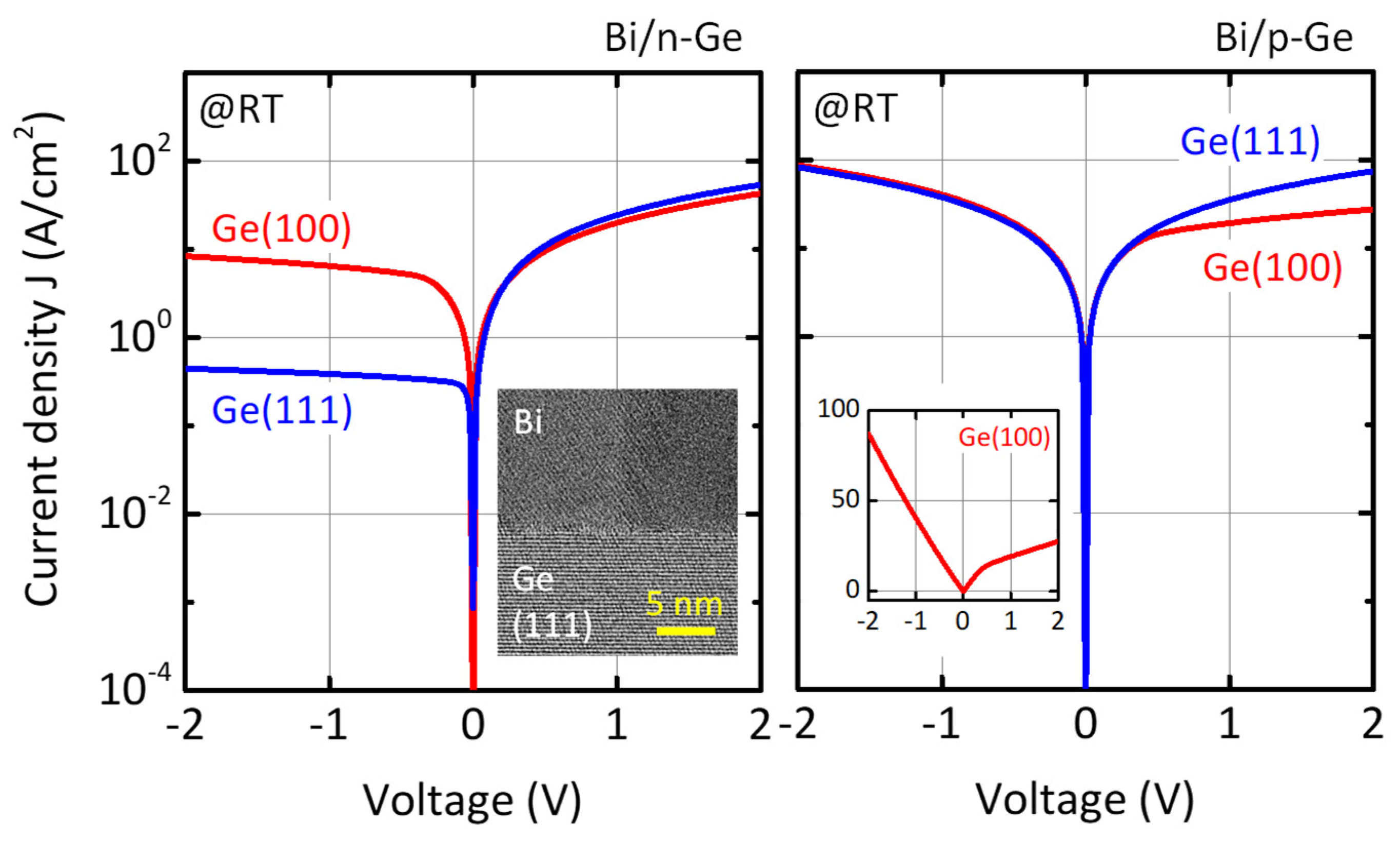
  97. Nishimura, T.; Luo, X.; Matsumoto, S.; Yajima, T.; Toriumi, A. Almost Pinning-Free Bismuth/Ge and /Si Interfaces. AIP Adv. 2019, 9, 095013. [Google Scholar] [CrossRef]
  98. Shen, P.-C.; Su, C.; Lin, Y.; Chou, A.-S.; Cheng, C.-C.; Park, J.-H.; Chiu, M.-H.; Lu, A.-Y.; Tang, H.-L.; Tavakoli, M.M.; et al. Ultralow Contact Resistance between Semimetal and Monolayer Semiconductors. Nature 2021, 593, 211–217. [Google Scholar] [CrossRef]
  99. Okada, N.; Uchida, N.; Kanayama, T. Fermi-Level Depinning and Contact Resistance Reduction in Metal/n-Ge Junctions by Insertion of W-Encapsulating Si Cluster Films. Appl. Phys. Lett. 2014, 104, 062105. [Google Scholar] [CrossRef]
  100. Iyota, M.; Yamamoto, K.; Wang, D.; Yang, H.; Nakashima, H. Ohmic Contact Formation on N-Type Ge by Direct Deposition of TiN. Appl. Phys. Lett. 2011, 98, 192108. [Google Scholar] [CrossRef]
  101. Wu, Z.; Wang, C.; Huang, W.; Li, C.; Lai, H.; Chen, S. Ohmic Contact Formation of Sputtered TaN on N-Type Ge with Lower Specific Contact Resistivity. ECS J. Solid State Sci. Technol. 2012, 1, P30–P33. [Google Scholar] [CrossRef]
  102. Seo, Y.; Lee, S.; Baek, S.C.; Hwang, W.S.; Yu, H.-Y.; Lee, S.-H.; Cho, B.J. The Mechanism of Schottky Barrier Modulation of Tantalum Nitride/Ge Contacts. IEEE Electron Device Lett. 2015, 36, 997–1000. [Google Scholar] [CrossRef]
  103. Suzuki, A.; Asaba, S.; Yokoi, J.; Kato, K.; Kurosawa, M.; Sakashita, M.; Taoka, N.; Nakatsuka, O.; Zaima, S. Reduction of Schottky Barrier Height for N-Type Ge Contact by Using Sn Electrode. Jpn. J. Appl. Phys. 2014, 53, 04EA06. [Google Scholar] [CrossRef]
  104. Baek, S.C.; Seo, Y.-J.; Oh, J.G.; Albert Park, M.G.; Bong, J.H.; Yoon, S.J.; Seo, M.; Park, S.; Park, B.-G.; Lee, S.-H. Alleviation of Fermi-Level Pinning Effect at Metal/Germanium Interface by the Insertion of Graphene Layers. Appl. Phys. Lett. 2014, 105, 073508. [Google Scholar] [CrossRef]
  105. Wei, Y.-N.; Hu, X.-G.; Zhang, J.-W.; Tong, B.; Du, J.-H.; Liu, C.; Sun, D.-M.; Liu, C. Fermi-Level Depinning in Metal/Ge Junctions by Inserting a Carbon Nanotube Layer. Small 2022, 18, 2201840. [Google Scholar] [CrossRef]
  106. Schroder, D.K.; Meier, D.L. Solar Cell Contact Resistance—A Review. IEEE Trans. Electron Devices 1984, 31, 637–647. [Google Scholar] [CrossRef]
  107. Peng, S.; Jin, Z.; Yao, Y.; Li, L.; Zhang, D.; Shi, J.; Huang, X.; Niu, J.; Zhang, Y.; Yu, G. Metal-Contact-Induced Transition of Electrical Transport in Monolayer MoS2: From Thermally Activated to Variable-Range Hopping. Adv. Electron. Mater. 2019, 5, 1900042. [Google Scholar] [CrossRef]
  108. Paramahans Manik, P.; Kesh Mishra, R.; Pavan Kishore, V.; Ray, P.; Nainani, A.; Huang, Y.-C.; Abraham, M.C.; Ganguly, U.; Lodha, S. Fermi-Level Unpinning and Low Resistivity in Contacts to n-Type Ge with a Thin ZnO Interfacial Layer. Appl. Phys. Lett. 2012, 101, 182105. [Google Scholar] [CrossRef]
  109. Yu, H.; Schaekers, M.; Demuynck, S.; Barla, K.; Mocuta, A.; Horiguchi, N.; Collaert, N.; Thean, A.V.-Y.; De Meyer, K. MIS or MS? Source/Drain Contact Scheme Evaluation for 7nm Si CMOS Technology and Beyond. In Proceedings of the 2016 16th International Workshop on Junction Technology (IWJT), Shanghai, China, 9–10 May 2016; pp. 19–24. [Google Scholar]
  110. Manik, P.P.; Lodha, S. Contacts on N-Type Germanium Using Variably Doped Zinc Oxide and Highly Doped Indium Tin Oxide Interfacial Layers. Appl. Phys. Express 2015, 8, 051302. [Google Scholar] [CrossRef]
  111. Kim, J.-K.; Kim, G.-S.; Nam, H.; Shin, C.; Park, J.-H.; Kim, J.-K.; Cho, B.J.; Saraswat, K.C.; Yu, H.-Y. The Efficacy of Metal-Interfacial Layer-Semiconductor Source/Drain Structure on Sub-10-Nm n-Type Ge FinFET Performances. IEEE Electron Device Lett. 2014, 35, 1185–1187. [Google Scholar] [CrossRef]
  112. Shayesteh, M.; Huet, K.; Toqué-Tresonne, I.; Negru, R.; Daunt, C.L.M.; Kelly, N.; O’Connell, D.; Yu, R.; Djara, V.; Carolan, P.B.; et al. Atomically Flat Low-Resistive Germanide Contacts Formed by Laser Thermal Anneal. IEEE Trans. Electron Devices 2013, 60, 2178–2185. [Google Scholar] [CrossRef]
  113. Miyoshi, H.; Ueno, T.; Hirota, Y.; Yamanaka, J.; Arimoto, K.; Nakagawa, K.; Kaitsuka, T. Low Nickel Germanide Contact Resistances by Carrier Activation Enhancement Techniques for Germanium CMOS Application. Jpn. J. Appl. Phys. 2014, 53, 04EA05. [Google Scholar] [CrossRef]
  114. Nishimura, T.; Toriumi, A. Nishimura, T. (The Univ. of Tokyo, Tokyo, Japan); Toriumi, A. (The Univ. of Tokyo, Tokyo, Japan) Unpublished work, 2016.
  115. Hutin, L.; Royer, C.L.; Tabone, C.; Delaye, V.; Nemouchi, F.; Aussenac, F.; Clavelier, L.; Vinet, M. Schottky Barrier Height Extraction in Ohmic Regime: Contacts on Fully Processed GeOI Substrates. J. Electrochem. Soc. 2009, 156, H522. [Google Scholar] [CrossRef]
  116. Martens, K.; Rooyackers, R.; Firrincieli, A.; Vincent, B.; Loo, R.; De Jaeger, B.; Meuris, M.; Favia, P.; Bender, H.; Douhard, B.; et al. Contact Resistivity and Fermi-Level Pinning in n-Type Ge Contacts with Epitaxial Si-Passivation. Appl. Phys. Lett. 2011, 98, 013504. [Google Scholar] [CrossRef]
  117. Kim, G.-S.; Kim, J.-K.; Kim, S.-H.; Jo, J.; Shin, C.; Park, J.-H.; Saraswat, K.C.; Yu, H.-Y. Specific Contact Resistivity Reduction Through Ar Plasma-Treated TiO2-x Interfacial Layer to Metal/Ge Contact. IEEE Electron Device Lett. 2014, 35, 1076–1078. [Google Scholar] [CrossRef]
Figure 1. Progress of effective carrier mobility in inversion channels [at inversion carrier density Ns = 5 × 10¹²/cm2 or effective electric field E = 0.5 MV/cm] of (a) p-FET and (b) n-FET. The line of “Si” corresponds to the universal mobility of Si FETs fabricated on (100) surface. In contrast to Ge p-FET, the performance of Ge n-FET was worse than Si n-FET at initial stage, but has been improved to be 2 times higher than Si universality. On the other hand, InGaAs (In0.53Ga0.47As) exhibits much higher electron mobility than Ge. However, there are other challenges such as small capacitance of inversion channel due to lower DOS, process compatibility with Si, control of stoichiometry, etc.
Electronics 11 02419 g001
Figure 2. (a) Schematic band alignment at metal/semiconductor interface with no charge transfer (no Fermi level pinning (FLP)). This is called Schottky limit and Schottky barrier height for conduction band of semiconductor Φ b n is equal to subtraction of electron affinity of semiconductor χ from vacuum work function of metal Φ m . Therefore, Schottky barrier height at the interface is controllable by vacuum work function of metal. (b) Schematic band alignment at metal/semiconductor interface with FLP. Due to charge transfer at the interface, Fermi level at the interface relative to band edge of semiconductor is shifted from Schottky limit in direction to charge neutrality level, where the charge neutral level is defined as Φ C N L from conduction band edge of semiconductor. In the case that S parameter is 0, Φ b n is equal to be Φ C N L irrespective of vacuum work function of metal and is not modulated by vacuum work function of metal. This is called Bardeen limit.
Electronics 11 02419 g002
Figure 3. (a) Schottky barrier height for conduction band of Ge Φ b n at metal/Ge(100) interface as a function of vacuum work function of metal Φ m . The barrier Φ b n values in the graph are estimated from I-V or C-V characteristics of metal/n-Ge diodes. Except for the result reported from Thanailakis, Schottky barrier height for conduction band of Ge at metal/Ge interface is almost constant, insensitive to vacuum work function of metal, and comparable to band gap of Ge (0.66 eV). The S parameter estimated from the slope in the plots is 0.02–0.05, which corresponds to interface states of ~1014 states/cm2/eV. To realize Ge device with electron channel, it is indispensable to overcome the strong FLP. Reproduced with permission from ref. [35], A. Thanailakis and E.C. Northrop; published by Elsevier, 1973, from ref. [36] E.D. Marshall et al.; published by Springer Nature, 2011, from ref. [37], A. Dimoulas et al.; published by AIP publishing, 2006, from ref. [38], T. Nishimura et al., published by Japan Society of Applied Physics, 2006, from ref. [39], T. Nishimura et al.; published by AIP publishing, 2007. (b) Typical I-V characteristics of metal/n-Ge(100) diodes. Schottky barrier height can be evaluated from the relationship of J s = A T 2 exp Φ b / k T , where J s , A and T is saturation current density, Richardson constant and measured temperature, respectively. The saturation current density J s is estimated from linear extrapolation of current density at V = 0 in the graph. Due to the strong FLP, rectified character appears irrespective of metals on n-Ge. On the other hand, typical metal/p-Ge diodes exhibit ohmic characteristics (not shown).
Electronics 11 02419 g003
Figure 4. (a) Typical I-V characteristics of metal/n-Si0.55Ge0.45(100) diodes measured at room temperature. The off-state current density on high work function metal diodes is increased at negative bias region, which might be caused by leakage through extrinsic defects in SiGe. However, saturation current density is obviously more dependent on metals compared with that of Ge diodes depicted in Figure 2b. (b) The correlation among FLP strength ( S parameter), band gap and crystallinity (FWHM of (400) diffraction peak in XRD) of semiconductors. The S parameter is simply increased with band gap of semiconductor independent of its crystallinity, which suggests intrinsic FLP mechanism dominantly characterizes the FLP at metal/Ge interface.
Electronics 11 02419 g004
Figure 5. (a) Characteristics I-V of Al/Ge(100) diodes and those of Al/ultrathin GeO2/Ge(100) ones. Due to the strong FLP close to valence band edge of Ge, as depicted in schematic, Al/Ge diodes exhibit Schottky characteristic and ohmic one for n- and p-Ge, respectively. On the contrary, Al/GeO2/Ge diodes show ohmic characteristic and Schottky one for n- and p-Ge, respectively, which indicates that the Fermi level at the interface is shifted towards to conduction band edge of Ge. (b) Cross sectional TEM image of Al/GeO2/Ge contact. It is observed that 2-nm-thick amorphous GeO2 layer is formed at the interface.
Electronics 11 02419 g005
Figure 6. The correlation between band alignment at metal/1-nm-thick GeO2/Ge(100) and vacuum work function of metal. That at metal/Ge(100) [38,39] are also shown. Schottky barrier height were estimated from saturation current density in I-V characteristics measured at room temperature and Richardson constant of Ge. The S parameter for metal/GeO2/Ge interface is estimated to be 0.14 and it is obviously more than that of direct metal/Ge one, which indicates that the FLP at metal/Ge interface is weakened by ultrathin GeO2 interlayer. Adapted with permission from ref. [38], T. Nishimura et al., published by Japan Society of Applied Physics, 2006, from ref. [39], T. Nishimura et al.; published by AIP publishing, 2007.
Electronics 11 02419 g006
Figure 7. (a) Summary of Schottky barrier height values at direct metal/n-Ge interfaces and metal/ultrathin interface layer/n-Ge ones. Various interface layers such as oxides and nitrides are effective to alleviate the FLP and improve controllability of the band alignment. By use of appropriate interface layer and metal, Schottky barrier height for conduction band edge of Ge can be efficiently reduced. Data from refs. [36,37,38,39,66,67,68,69,70,71,72,73,74,75,76]. (b) Summary of S parameters at direct metal/n-Ge interfaces and metal/ultrathin interface layer/n-Ge ones. There might still be process dependence, but it is sure that the strong FLP at metal/Ge interface is weakened by insertion of interface layer. Data from [36,37,38,39,66,68,70,75,76].
Electronics 11 02419 g007
Figure 8. (a) Schottky barrier height for the conduction band of Ge at metal/GeO2/n-Ge(100) interface as a function of the thickness of GeO2. All metal electrodes were formed on the single Ge wafer with beveled GeO2 layer and Schottky barrier height was estimated approximately from saturation current density and Richardson constant of Ge(100). The thickness of GeO2 layer was determined by spectroscopic ellipsometry. Reproduced with permission from ref. [68], T. Nishimura et al., IEEE Proceedings; published by IEEE, 2010. (b) S parameter as a function of interface layer thickness. In addition to the S parameter for metal/beveled GeO2/Ge estimated from (a), other results are also depicted. The S parameter is not drastically, but rather gradually increased with interface layer thickness at least in case of GeO2, which suggests that the FLP alleviation at metal/ultrathin insulator/Ge interface is caused by thickness effect of interface layer. Data from refs. [68,75,76].
Electronics 11 02419 g008
Figure 9. (a) Typical I-V characteristics of germanide/n-Ge(100) diodes measured at room temperature. All germanides were formed by thermal reaction of deposited single-element metal with Ge at 500 °C. The off-state current density of germanide/n-Ge diode is much dependent on metal compared with that of single-element metal/n-Ge diode shown in Figure 2b. Adapted with permission from ref. [92], T. Nishimura et al., published by IOP publishing, 2008. (b) The relationship between the band alignment at germanide/Ge(100) interface and vacuum work function of metal. The vacuum work function of germanide is estimated from the group electronegativity [ Χ A m B n = Χ A m Χ B n m + n ] [84] and the correlation between electronegativity and vacuum work function [ Φ m = 2.27 Χ P a u l i n g + 0.34 ] [85]. It is obvious that the FLP at germanide/Ge interface is much weaker than that at simple element metal/Ge one.
Electronics 11 02419 g009
Figure 10. (a) I-V characteristics of Gd and Gd-germanide/n-Ge(100) and (111) diodes. The I-V characteristics of Gd/Ge diodes are not dependent on Ge surface orientation, while those of Gd-germanide/Ge ones are strongly dependent. In addition, Gd-germanide/n-Ge(111) diode surprisingly exhibits ohmic character, as also shown in the inset. The interface structure dependence in I-V characteristics of germanide/Ge diodes is possibly understandable by appearance of other mechanisms which are masked by MIGS at typical single-element metal/Ge interface. Adapted with permission from ref. [92], T. Nishimura et al., published by IOP publishing, 2008. (b) Cross sectional TEM image of Gd-germanide/Ge(111) interface formed by thermal reaction of Gd with Ge. It is confirmed that direct germanide/Ge interface is certainly formed and the Schottky barrier height lowering is never caused by unintentional interface layer growth at the interface.
Electronics 11 02419 g010
Figure 11. I-V characteristics of Bi/n-Ge and /p-Ge diodes with various Ge surface orientation. The off-state current density of Bi/n-Ge diodes are much higher than that of single-element metal/Ge ones, shown in Figure 2b, and Bi/p-Ge(100) diode shows rectified I-V characteristics, as also shown in the inset. The Bi/Ge interfaces were fabricated by deposition process, which is same to fabricate the single-element metal/Ge interfaces. As shown in the cross-sectional TEM image in inset, direct Bi/Ge interface formation is confirmed. However, Schottky barrier height for conduction band of Ge at Bi/Ge(100) and /Ge(111) are estimated from saturation current density to be 0.37 and 0.44 eV, respectively. This band alignment is out of trend of strong FLP observed at single-element metal/Ge interface. The Ge surface orientation dependence on the Schottky barrier height at Bi/Ge interfaces might purely be caused by difference of Ge surface orientation.
Electronics 11 02419 g011
Figure 12. Summary of reported Schottky barrier height at low free-electron-density metal/n-Ge interface. Schottky barrier height for Ge is very controllable by appropriate metal and interface structure even at direct metal/Ge interface. In some case of metallic nitrides, Schottky barrier height for conduction band of Ge is much less than half of Ge band gap (0.33 eV). Considering the process compatibility of nitride metal with Si technology, those metals may also be possible candidates for practical application. Data from refs. [36,37,38,39,86,87,88,89,92,97,99,100,101,102,103,104].
Electronics 11 02419 g012
Figure 13. Contact resistivity at various metal/n-Ge interfaces. The calculated contact resistivities with various Schottky barrier heights are denoted in broken lines, where tunneling effective mass of electron of 0.12 m0 and relative dielectric constant of 16 is assumed. The doped ZnO and ITO looks possible to achieve ~10−9 Ωcm2 by increasing doping density. The calculated total resistivity at rare earth metal germanide (REGex)/n-Ge interface is also shown with solid line, assuming that Schottky barrier height is 0.3 eV and bulk resistivity of 5-nm-thick REGex (~5 × 10⁻¹⁰ Ωcm2). Data from refs. [108,110,111,112,113,116,117].
Electronics 11 02419 g013
Publisher’s Note: MDPI stays neutral with regard to jurisdictional claims in published maps and institutional affiliations.

