1. Introduction
With the global construction of 5G and the combination of 5G and the Internet of Things (IoTs), more and more application requirements have emerged, such as virtual reality/augmented reality (VR/AR), holographic communication, large-scale industrial IoTs, smart Internet of Vehicles (IoVs), and unmanned aerial vehicles (UAVs) [
1,
2]. These new applications have higher requirements in terms of the number of connections, delays, throughput, and reliability of communication systems. However, the current mobile communication network cannot meet the communication requirements of future novelty applications and will evolve in a way towards higher frequency bands and larger bandwidths [
3]. To meet the higher demand of future applications, 6G, as the next-generation advanced mobile communication system, has become a research hotspot in the past two years. In order to realize the integration of sensing and communication, computing and control, 6G will be deeply integrated with many advanced technologies, such as smart IoTs, big data, artificial intelligence (AI), blockchain, cloud computing, and edge computing. The 6G network will become the basic guarantee for serving human life, empowering social production, and globalizing green development.
A number of key core technologies and new network technologies are required to make breakthroughs in the 6G era to meet the richer service requirements and the ultimate user experience. The 6G network will further expand to higher frequency bands such as millimeter wave (mmWave) and terahertz (THz) on the basis of deep plowing and replowing existing spectrum resources. Moreover, the different spectrum resources will be used comprehensively and efficiently to meet the service needs of different application scenarios of 6G. Terahertz communication is a fundamental key technology of 6G which can be used as a beneficial supplement and enhancement to the existing air interface transmission technologies. The terahertz frequency band (0.1–10 THz) is between microwave and visible light, with extremely rich spectrum resources, high transmission rate, strong anti-interference ability, etc., which can meet the needs of future communication systems, such as Tbps-level large capacity, ultra-high transmission rate, ultra-dense device connection, etc. The 6G network based on terahertz communication will play an important role in fields such as large-scale industrial IoT applications, holographic communication, high-precision positioning, and high-resolution perception in the future.
However, the penetration and diffraction capabilities of THz signals are very weak, and they are easily blocked by obstacles, resulting in very unstable signal transmission [
4]. It is expected this problem will be alleviated by deploying reconfigurable intelligent surfaces (RISs). RISs have been a research hotspot in wireless communication in recent years, and they are also one of the potential key technologies of 6G. They can greatly enhance the 6G air interface transmission capability, and they are expected to be applied to various scenarios, such as coverage enhancement, transmission rate enhancement, and assisted electromagnetic environment awareness in high-frequency 6G systems [
5,
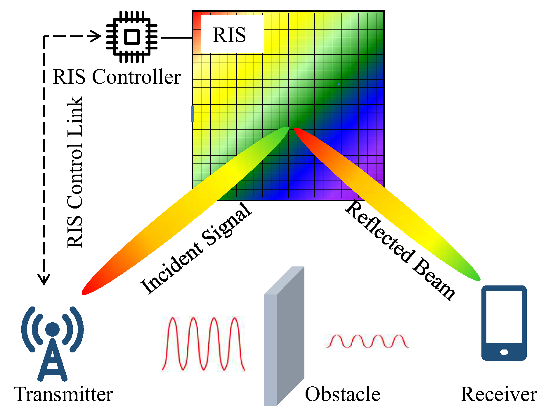
6]. An RIS is a reflective plane composed of a large number of passive reflective units. Each reflective unit is a simple circuit composed of some low-cost passive electronic components (such as resistors, capacitors, diodes, etc.) and can reflect the incident waves independently. The intelligent controller is the control core of an RIS, which adjusts the reflection amplitude and phase of each reflection unit by controlling its output signal, to realize RIS beamforming. An RIS can compensate for power loss by reconfiguring the wireless propagation environment to overcome the non-line-of-sight (NLOS) limitation and build an intelligent and controllable wireless environment.
As a new and promising transmission technology, the main capabilities of RISs include RIS-enhanced signal transmission [
7,
8], RIS-assisted signal neutralization [
9,
10], RIS-assisted Simultaneous Wireless Information and Power Transfer (SWIPT) [
11,
12], RIS-assisted secure communication [
13,
14], and so on. Based on these excellent capabilities of RISs, a large number of applications of RIS in wireless communications has been optimistically predicted. The more attractive application is the large-scale industrial IoT application based on RISs. For example, multiple RISs can be deployed at suitable locations in factories and workshops, and the signal enhancement capabilities of RISs can be used to greatly increase the transmission rate of data acquired by various sensors and cameras to ensure the implementation of smart factory applications. RIS-assisted SWIPT can be used to provide continuous online wireless charging for energy-limited IoT nodes (also known as energy receivers), thereby extending the working time of IoT terminals. This is of great significance to meet the energy needs of small cell networks and future large-scale IoTs [
15,
16]. In wireless network security communication, the signal neutralization capability of RISs helps to reduce the eavesdropper’s receiving power as much as possible, thereby greatly reducing the eavesdropper’s acquisition of legitimate user information and ensuring the security of industrial IoT applications.
Wireless channel modeling is a fundamental issue for studying any wireless communication technology [
17]. In an RIS-assisted terahertz communication system, establishing an accurate channel model is the basis for system design and optimization [
18]. Currently, an important limitation of the research on RIS-enabled wireless communication applications is the lack of easy-to-operate and accurate RIS channel models. Some preliminary research work has been carried out in this area recently. Ref. [
19] studies the path loss model of RIS-assisted wireless communication under different conditions. Ref. [
20] uses the Huygens–Fresnel principle to study the wireless channel of reflective RIS and gives a closed expression for calculating the received power of RISs. Ref. [
21] verifies the proposed RIS free space path loss model experimentally, and the measurement results show that the established model has strong credibility. Considering the influence of RIS panel size and terminal mobility on RIS channel characteristics, an RIS geometric randomness channel model in three-dimensional (3D) space is established in [
22]. An aerial RIS channel model is established in [
23], which is divided into the sub-channel model between the drone and RISs and the sub-channel model between RISs and the receiver. In the current research, most of the RIS-assisted wireless systems are based on a long-distance channel model. In fact, in order to obtain the best system performance, RISs may be deployed near the base station (BS) or users. In this case, it is necessary to introduce a near-field propagation model to make a more realistic path loss measurement for RISs.
The main contribution of this paper is that, on the premise of giving a concise near-field distance model for RIS communication, the channel models of RIS-assisted wireless communication in the far-field and near-field conditions, separately, are studied theoretically. It is proved by simulations that the received signal quality in the target area and system throughput can be greatly improved by deploying large-dimension RIS reflector arrays at appropriate locations under the strong guarantee of THz ultra-large bandwidth. Therefore, RISs are expected to be one of the key technologies to improve the coverage performance of 6G THz communication systems. This conclusion can undoubtedly bring great confidence to the successful application of new 6G applications, such as VR/AR, holographic communication, and large-scale industrial IoT, in the future.
The rest of the sections are organized as follows. In
Section 2, we analyze the near field and far field of antenna arrays in detail, and the RIS-assisted wireless communication system is described.
Section 3 presents RIS-assisted terahertz communication channel modeling for far- and near-field beamforming, respectively. Simulation and result analysis are carried out in
Section 4. Finally,
Section 5 concludes this research.
2. Problem Formulation
2.1. Far Field and Near Field
The receiving antenna may be in the far field or near field of the transmitting antenna, which is closely related to the distance between them. When this distance is far enough, it is generally considered that the receiving antenna is in the far field of the transmitting antenna, and vice versa, it is considered to be in the near field. In the far-field case, the spherical wave generated by the transmitter can be approximated as a plane wave when it reaches the receiving antenna array, that is, the phases of the arriving signals are approximately equal. However, when the transmitter is close to the antenna array, or the surface area of the antenna array is very large, the phase difference of the arriving signals cannot be ignored. The demarcation radius
D is defined as [
24]
where
L represents the maximum size of the receiving antenna array and
represents the wavelength. The RIS surface can be considered as a large-scale antenna array. Therefore, in an RIS-assisted terahertz communication system, we adopt the same definition for the antenna radiation area.
From Equation (
1), it is easy to obtain
where
f represents the operating frequency in THz. It can be seen that for terahertz communication, due to the extremely high frequency and large bandwidth, the range of the near-field region is much larger than that of the low-frequency band. Equation (
2) also shows that when the RIS surface is large enough, the delay between different RIS units can no longer be ignored. Therefore, the spatial broadband effect and the size of an RIS have a non-negligible influence on the channel modeling of an RIS-assisted terahertz communication system, which greatly affects the system performance. The near-field distances of different antenna sizes at different frequency points are shown in
Table 1.
2.2. System Description
In terahertz communication systems, multiple antennas, even ultra-massive multi-input multi-output (UM-MIMO), are needed to solve the problem of ultra-short distance. At the same time, the high-gain narrow beam of the transmitter points to the strongest propagation path to compensate for extremely high path attenuation. We consider a single-cell network scenario covered by a multi-antenna base station in this paper. The number of transmit antennas of the BS (as the source end) is denoted as
M, the number of RIS reflection units is denoted as
N, and the single-antenna user equipment (UE) serves as the receiving end. RIS units are regularly distributed, with
P rows and
Q columns (
), and the size of each unit is within the sub-wavelength size range, as shown in
Figure 1.
The direct link from BS to UE is represented by , and represents the channel response from the jth antenna of BS to UE, . The channel from BS to RIS is represented by , and represents the channel response from the jth antenna of BS to the ith reflection unit of the RIS. The channel from RIS to UE is represented by , and represents the channel response from the ith reflection unit of the RIS to UE, . Note that in this paper, italic letters (such as M) are used to represent scalars, bold lowercase letters (such as ) represent vectors, and bold capital letters (such as ) represent matrices.
In RIS-assisted wireless communication, the reflection characteristics of the RIS itself play a vital role in the transmission of the BS-RIS-UE wireless link (referred to as the auxiliary link in this paper). RIS reflection is characterized by its influence on the amplitude and phase shift of the incident wave. The reflection phase matrix of the RIS is denoted as , and the reflection amplitude is denoted as . Since the RIS reflection units are passive and do not have the function of amplification, . represents the full absorption of the incident wave, and represents full reflection.
The reflection coefficient matrix of the RIS is defined as . Because each reflection unit of the RIS is independent, it only reflects the incident wave on itself according to its reflection characteristics, so is designed as a diagonal matrix. This paper assumes that RISs can reflect the incident wave with approximately constant gain in all target directions, that is, it is assumed that each reflection unit has the same amplitude of , .
The channel of the auxiliary link is expressed in cascaded form, namely . Therefore, the combined channel of the two paths from BS to UE (that is, the direct link and the auxiliary link) is expressed as .
Let be the weight vector of the BS antennas, which satisfies . represents the norm or Euclidean norm of the vector .
3. RIS-Assisted Terahertz Communication Channel Modeling
3.1. Channel Modeling in the Case of Far-Field Beamforming
When the RIS is in the far field of the base station, the reflected signals of all RIS units can be aligned with each other and point to the target area to enhance the received signal power, thereby achieving a high-precision beamforming effect.
Considering the influence of transmit power on signal transmission [
25], the received signal at UE can be expressed as
It can also be expressed as
where
represents the total transmit power and
x is the information data transmitted per unit-power. Gaussian white noise is
. Suppose
x is an independent random variable represented by the power normalization, with zero mean and unit variance.
The SNR at the receiver is
The channel capacity of the wireless link supported by RIS is
According to the properties of complex numbers,
The equality sign of the above equation is true if and only if the phases of the radio waves of all M BS transmitting antennas reaching UE through the direct link are exactly the same as those of N RIS reflecting units reaching UE through the auxiliary path. In this way, it can be ensured that the arrival signals transmitted on the two-path link are coherently added at the UE and the energy of the received signal is maximized, thereby achieving the maximum data transmission rate.
Let , where and represent the corresponding optimal values, respectively.
According to the operation properties of complex number multiplication,
where
l and
k respectively take a certain integer and we ensure that
and
.
3.2. Channel Modeling in the Case of Near-Field Beamforming
According to [
19], under the same antenna panel area, the higher the operating frequency band, the greater the number of antenna elements and the farther the far-field distance. Moreover, in order to increase the RIS gain, the RIS is generally likely to be deployed near base stations. Therefore, it is very necessary to introduce a near-field model into terahertz-enabled communication systems to analyze the propagation characteristics of RISs. We consider the case of near-field RIS-assisted SISO communication, as shown in
Figure 2.
In
Figure 2, it is assumed that the RIS reflection plane is placed on the
plane in the space coordinate system, and its geometric center is at the origin of the coordinates.
P and
Q denote the number of reflection units in the
x-direction and
y-direction, respectively. For the convenience of analysis, it is assumed that both are odd numbers, that is, the origin of the coordinate is located in the central reflecting unit. The lengths of the reflecting units along the x-direction and the y-direction are denoted by
and
, respectively, and the sizes are between
and
.
The center coordinate of any RIS unit is , where and .
Consistent with the analysis in [
21], we use
and
, respectively, to denote the distance, elevation angle, and azimuth angle from the base station to the RIS reflection unit
. Similarly, the corresponding parameters from the UE to the RIS reflection unit
are represented by
and
, respectively.
For simplicity, the path difference information on the RIS reflection unit
is concentrated on the reflection coefficient. By designing a reasonable RIS reflection coefficient, the reflected signal can be focused on the receiver antenna. Assume that the complex reflection coefficient
has an adjustable amplitude
and different phase shifts
.
, where the phase delay is
Note that the symbol represents the rounding function.
The relative path difference of the reflection unit
to the reference unit
is
and represent the normalized power radiation patterns of the transmitting and receiving antennas, respectively, which indicate the relationship between the power density and the azimuth/elevation angle.
The received signal power is
where
.
The signal received by the RIS reflection unit
is
Since RIS is a two-dimensional planar structure, we have
The received signal in the time domain is
where
represents the time delay from the
lth transmitting antenna to the RIS central unit.
The received signal at frequency point
f in the frequency domain is
It can be further obtained that
The received signals in the frequency domain on all RIS units can be expressed in matrix form as follows:
Equation (
20) can be vectorized as
where
.
4. Simulation Results and Analysis
In addition to the usual wireless propagation influencing factors, there are other unique factors that also affect the performance of RIS-assisted wireless communication systems, such as RIS antenna array characteristics (including reflective units’ size and structure, RIS surface size and shape, etc.) and RIS deployment location (including relative location to BS and target area, surrounding environment, etc.). These unique factors are a very big challenge for the theoretical modeling of RIS channels. In addition, the accuracy of RIS hardware design and the phase shift control and beamforming mechanisms can also affect the performance of RIS-assisted communication systems. In order to obtain the influence trends of key metrics using simulation, the channel models are often appropriately simplified. In this paper, we assume that instantaneous channel state information can be obtained deterministically and that RIS phase shift control can perfectly achieve the coherent summation of reflected waves at UE.
This paper simulates the performance of the wireless auxiliary link in an RIS-based mobile communication system. Assume that the direct link between BS and UE is completely blocked. The RIS surface is a square, and each reflection unit is a small square, that is,
and
. The main simulation parameters are shown in
Table 2.
Assuming that the size of each RIS unit is
and the spacing between RIS units is as large as RIS units, according to Equation (
2), given the distance between BS and RIS, the critical value of RIS antenna arrays for near-field communications can be calculated.
Figure 3 gives the critical value of RIS antenna arrays (expressed by the number of RIS cells) for near-field communications under four different operating frequency bands, corresponding to the different distances between BS and RIS. When the actual RIS size is smaller than the critical value, the RIS is in the far-field communication area, and vice versa in the near-field communication area.
Figure 3 illustrates that a larger RIS antenna array is required due to the expected smaller RIS units at higher operating frequency bands. It can be obtained from
Figure 3 that when the distance between BS and RIS is 150 m, corresponding to these four different frequency bands, the critical values of RIS antenna arrays are 30, 158, 352, and 498, respectively.
Figure 4 simulates the performance of the RIS auxiliary link in terms of SNR. In the simulation, we appropriately consider the far-field and near-field channel models which are labeled in
Figure 4. When the RIS surface reflects the incident signal with the optimal phase,
Figure 4 shows that the SNR at UE increases with the increase in the RIS surface as a whole, which shows that increasing the size of the RIS surface is an effective way to increase the SNR. However, with the increase in the RIS surface, the growth of SNR slows down and approaches a corresponding constant. According to the definition of asymptotic channel hardening in an RIS-assisted wireless communication system in [
26], when
, the RIS-assisted wireless link shows channel hardening characteristics. Therefore, the RIS must be properly configured to obtain greater SNR.
Figure 4 also shows that under the same bandwidth conditions, the performance of the THz communication system is far lower than that of 5G (the mainstream frequency band of 5G is
GHz). The higher the operating frequency, the worse the communication performance. Therefore, we expect to improve the performance of the THz communication system through larger RIS panels, greater transmission power, and other more advanced technologies.
Figure 5 compares the system throughput under different operating frequency bands. For the 3.5 GHz system, we allocated 100 MHz bandwidth (BW), which is the maximum bandwidth available for 5G. Moreover, for the three THz systems with more abundant frequency resources, we allocated 1 GHz bandwidth.
Figure 5 shows that when the RIS antenna array is small, although RIS improves the throughputs of the THz systems significantly, the THz system performance is still inferior to that of 3.5 GHz. However, with the increase in the RIS antenna arrays, the RIS-assisted THz system performance is rapidly enhanced, which can be seen from the concave throughput curve.
Figure 6 reflects the influence of different RIS reflection unit sizes on the SNR. The RIS reflector unit is very small, usually in the sub-wavelength range. When
THz,
corresponds to the reflection unit sizes of
mm,
mm, and
mm, respectively.
Figure 6 shows that in the RIS-assisted THz communication system, the smaller the reflection unit, the lower the SNR. This indicates that when RIS reflection units and their spacing are small to a certain extent, the RIS surface is similar to a large reflector, thus losing the reflection gain brought by RIS reflecting units.
Overall, the simulations in this section illustrate that in RIS-assisted 6G THz communication systems, the SNR performance of the received signals can be improved and the system coverage can be extended by increasing the system bandwidth and deploying large-area RIS reflective arrays. This advantage implies RIS could be widely and successfully used in 6G THz communication systems and help the realization of future new 6G applications, such as VR/AR, holographic communication, and large-scale industrial IoTs, which have very high requirements in terms of throughput, coverage depth, and coverage breadth [
16,
27,
28]. The combined use of RISs may break through the transmission and coverage limitations of THz communication in 6G applications.
5. Conclusions
Terahertz communication and RIS are two new technologies that will greatly affect the future 6G communications and will play an important role in future novel applications such as large-scale industrial IoTs. This paper combines these two technologies and theoretically studies the wireless channel model of RIS-based terahertz-enabled communication systems. We study the relationship between SNR and the RIS surface size and operating frequency by simulation in this paper. However, compared to traditional wireless communication systems, RIS channel modeling faces new and severe challenges, such as the size, number, and layout of RIS reflective units. When constructing the RIS channel model, many factors need to be considered, such as the operating frequency band, the deployment method, the characteristics of the RIS itself, and so on [
29]. In addition, there should also be a balance between simplicity and usability as well as accuracy and complexity. Undoubtedly, although theoretical channel modeling and the results obtained by software simulation can reflect certain trends, they cannot accurately reflect actual wireless channel propagation. There are a small number of research institutes and companies, such as in China the State Key Laboratory of Millimeter Waves at Southeast University and the ZTE Corporation, which are working on the RIS hardware design and experimental performance verification of RIS-assisted wireless communication based on different scenarios such as indoors and outdoors with obstruction [
30,
31]. However, limited by the frequency range of current most signal generators, the hardware systems they design generally operate in the frequency band of several GHz such as
GHz. Therefore, it seems that there is still a long way to go for the hardware design and practical verification of RIS-assisted communication systems based on higher frequency bands such as millimeter wave and THz.
With the development of integrated communication and perception technology, it could be a development trend to use the perceived information such as location and image to assist in RIS channel modeling and channel estimation. In order to make full use of the various data acquired, artificial intelligence (AI) technology can also be introduced to cope with the complex scenarios and uncertainties in actual communication systems. In this way, a better performance than that of traditional technologies can be obtained on the premise of greatly reducing computational overhead. Our next research work may also include narrower beamforming RIS, shape-adaptive RIS, etc.


 ,
, 


