Article

New Sliding Mode Control Based on Tracking Differentiator and RBF Neural Network

School of Electric Power, Shenyang Institute of Engineering, Shenyang 110136, China
*
Author to whom correspondence should be addressed.
Electronics 2022, 11(19), 3135; https://doi.org/10.3390/electronics11193135
Submission received: 29 August 2022 / Revised: 26 September 2022 / Accepted: 27 September 2022 / Published: 29 September 2022

Abstract

:
In order to solve the problem that the control system of permanent magnet synchronous motor (PMSM) is difficult to meet the high control accuracy due to the influence of non-repeated disturbances such as external disturbance, system parameter variation, and friction force during operation, a novel sliding mode control (NSMC) method based on tracking differentiator (TD) and radial basis (RBF) neural network was proposed. Firstly, a new sliding mode reaching law is proposed by adding the state variables to the traditional exponential reaching law, which can effectively reduce the chattering of the system. Then, the speediest tracking differentiator is designed to estimate the given speed signal and its differential signal, to realize the novel sliding mode variable structure algorithm. Finally, the RBF neural network is used to compensate for the uncertainty and external interference of the system; the robustness of the system is further improved by adaptive weight updating. The simulation results show that, by comparing with the traditional exponential approach law, the overshoot of 22 r/min is reduced by the control method based on the new hybrid reaching law, the speed decrease amplitude is reduced by 77.1% under load disturbance, and the speed recovery time is shortened by 0.059 s. After the optimization of the new sliding mode control method based on tracking differentiator and RBF neural network, the overshoot of 86 r/min is further reduced, the speed decrease amplitude of load disturbance is reduced again by 48.5%, and the speed recovery time is shortened again by 0.073 s.

1. Introduction

PMSM is a key component in the control system of electric vehicles and robot equipment because of its high-power factor and easy maintenance [1,2,3]. The traditional direct torque control (DTC) system adopts the proportional-integral (PI) speed regulation strategy, which has problems such as large flux and torque pulsation, and it is difficult to control at the low speed [4]. It is not easy to meet the high requirements for motor control performance. Consequently, it is of great significance to study the speed tracking accuracy of direct torque control of PMSM.
To meet the requirements of PMSM for tracking the accuracy of the speed control system, relevant scholars apply sliding mode control, fuzzy control, adaptive control, and other control theories to the PMSM speed control system [5,6]. Among them, sliding mode control (SMC) is a control method with strong robustness and high stability [7]. It has very good control performance in motor speed control systems and has been widely used, but the traditional sliding mode also has some problems, such as obvious chattering. Therefore, domestic and foreign scholars have carried out extensive research. In reference [8], a proposed novel control method combines a novel sliding-mode reaching law-based controller with a proportional-integral observer. It can reduce the influence of external disturbance and system parameter changes on the speed response. After the motor test, the overshoot of the ASMC + MROPIO control is 16% lower than that of the PI control, and the maximum speed error is 155 r/min lower. However, the accuracy of the mathematical model of the control system is required. Literature [9] proposes a novel sliding mode control method. This method can solve the control problems faced by the controller, and the control method has a fast response to the fast dynamic transient of IPMSM. The results show that it can solve the overshoot problem. The proposed control model reaches steady-state speed in a faster time, 4.5 s faster than the PID controller. However, this method does not consider the influence of system disturbance on the control performance. Literature [10] proposed a new approach to law, expressed as a piecewise function, with a good chattering suppression effect. Furthermore, the extended state observer is used to estimate the disturbance and combined with sliding mode control, the robustness and control accuracy of the system are further improved, and the chattering of the system is weakened. In reference [11], a new fractional sliding mode surface is established, and based on this, a fractional sliding mode controller is applied in the permanent magnet DC motor. Through experiments, it is found that the proposed new controller has a good tracking effect and strong anti-interference during operation. However, the sliding mode control alone cannot guarantee the system’s anti-interference. The literature [12] proposed a new approach to law. By analyzing the principle of action, we can find out that the approach to law can change with the change of the system state. As the system gets closer and closer to the sliding surface, the approach speed also becomes smaller and smaller. Through analysis, it is found that chattering of the sliding mode is effectively suppressed. By combining the extended disturbance observer with the sliding mode control, the robustness of the control system is improved, and the precise control of the speed is further ensured. However, this observer requires careful consideration of the actual model of the motor, which greatly affects the effect of the observer. In reference [13], a synovial controller and high-order sliding mode observer were added to the vector control system of the brushless DC motor to improve the dynamic response of the motor and estimate the speed and position. After the hardware test, the error of speed tracking and torque ripple was significantly reduced. The error performance index and torque ripple were reduced by 5.84%. The literature [14] proposed a sensorless direct torque control method based on sliding mode control. The method reduces the influence of external and system parameters on the control effect, and the results show that it has good control performance. Reference [15] combines the non-singular terminal sliding mode controller with the interference estimator to form a new type of mechanical control mechanism. Under the premise of ensuring the control performance of the system, the service life of the components is improved. The test results show that the control structure has excellent performance and robustness. However, the system’s complexity is increased, and the time of adjusting parameters is greatly increased. Sliding mode control of ship paths is studied in Ref. [16]. To improve the control tracking accuracy and stability of the system, sliding mode nonlinear control is adopted, and the RBF neural network is used to approximate the unknown term and the gain of the rudder angle. The results show that the proposed method has better performance in both straight and curved conditions. The literature [17] proposed an RBF neural network sliding mode observer using the minimum parameter self-learning algorithm, which can effectively improve the control effect of the system. However, the network has the problems of fixed structure and slow learning speed. In order to make the performance of the fault-tolerant system better, reference [18] proposed a proportional integral differential non-singular fast terminal sliding mode surface. It used a fuzzy approximator to approximate the uncertainty and an adaptive law to approximate the error. The simulation results show that the response is faster and the robustness is better. Reference [19] proposed an improved exponential approximation law and used a fuzzy neural network to optimize the sliding mode controller dynamically. Compared with the traditional index, the overshoot is reduced by 6.6% after fuzzy neural network optimization. The decrease in rotational speed is reduced by 5.59%; the speed recovery time is reduced by 0.0132 s. However, the selection of relevant rules of fuzzy control needs to rely on a lot of experience, and improper selection may lead to the reduction of control accuracy. In reference [20], an improved Yolo-Tomato model was proposed for Tomato detection under complex conditions, which combined with LWYS technology, Mish, and SPP technology to improve the detection accuracy and intelligence of the detector. The results show that the average accuracy (AP) is as follows: Yolo-tomato-C > Yolo-tomato-B > Yolo-tomato-A; The detection time was compared as follows: Yolo-tomato-C > Yolo-tomato-A > Yolo-tomato-B, and the detection performance was greatly enhanced. In reference [21], the adaptive algorithm of the RBF neural network is added to the sliding mode controller to compensate for the uncertainty and external interference. The experiments show that the tracking performance is stronger, and the steady-state performance is better. However, when noise disturbance occurs, the system cannot meet the requirements of high control accuracy. Reference [22] proposes a novel multiscale feature fusion convolutional neural network, which uses transfer learning to capture EEG signals from different convolutional scales to classify motor imagery. The experimental results show that the average classification accuracy of the model is 94.06% (±0.70%), and the kappa value is 0.88. Reference [23] proposes a novel global differentiator that combines high-order sliding mode and dynamic gain to reduce the effects of uncertain perturbations in nonlinear systems. The control method only uses the dynamic gain of the state norm observer update of the input and output information. The results show that the system can ensure stable operation ability and accurate tracking ability of the system. Reference [24] adopts the adaptive algorithm of monitoring function in the closed-loop output feedback. Based on this, an adaptive high-order sliding-mode accurate differentiator gain algorithm is proposed. Sliding mode surfaces consist of globally accurate finite-time estimates of variables. Experiments show that the control algorithm can ensure accurate tracking ability.
After the above analysis, it is found that there are still some problems in the existing control methods: some control methods have limitations, the control system is too complex and fixed, the adjustment parameter time is long, the system has a large overshoot, the control accuracy is poor, and so on. The biggest problem with sliding mode control is the chattering problem. Improving the chattering problem by improving the reaching law has always been a research hotspot. If the sliding mode control contains a discontinuous switching function, the chattering will be more serious. If only sliding mode control is used, the system’s robustness cannot be guaranteed. To improve the above problems, a novel sliding mode velocity control method based on tracking differentiator and RBF neural network is proposed in this paper. Combined with the literature [12], a new hybrid sliding mode reaching law is designed, which can make the system state converge to the equilibrium point faster and effectively weaken the chattering phenomenon of the system. The fastest tracking differentiator is used to estimate the tracking signal and its differential signal of a given speed signal. In this paper, RBF neural network is used to approximate the total disturbance f , which ensures the anti-disturbance ability and adaptive ability. It does not rely on an accurate mathematical model. The control rules do not require too much experience, and the learning speed is fast. Simulation results show that the control method has better control performance.
The chapters of this paper are introduced as follows: In Section 2, the mathematical model of PMSM and the direct torque control system are derived. In Section 3, the principle and design of the velocity controller, the speedest tracking differentiator, and the RBF neural network based on the new reaching law are introduced in detail, and the stability proof is given. In Section 4, the new control method is verified by simulation under two conditions: constant load and load disturbance. The Section 5 is the conclusion of this paper.

2. System Modelling

The direct torque control strategy is adopted in this paper, and the simplified PMSM model in the D–Q axis is:
{ u d = R i d + L d d d t i d w L q i q u q = R i q + L q d d t i q + w ( L d i d + ψ f ) T e = 3 2 p n i q ψ f
where u d and u q are the dq axis component of the stator voltage; R s is stator resistance; i d and i q are the dq axis component of the stator current; L d and L q are the inductance of the dq axis; w is electric angular velocity; ψ f is permanent magnet flux; T e is electromagnetic torque; p n is the polar logarithm.
The equation of motion of PMSM is:
J p n w · = T e T L B w
where J is the moment of inertia; B is the friction coefficient, which is generally very small; T L is the load torque; w is the mechanical angular velocity.
If the influence of system parameter changes, external disturbance and friction, and other uncertain factors on the PMSM direct torque control system is ignored, Equation (2) can be rewritten as the equation of motion under the ideal state.
w · = p n B J w + p n T e J = p n B J w + p n u J
where u is the control rate of the controller and u = T e .
However, in practical application, the total disturbance of the control system has a great influence on the accuracy and robustness of the control, which cannot be ignored. Equation (2) can be rewritten as
w · = a T e b T L c w = ( a n + Δ a ) T e ( b n + Δ b ) T L ( c n + Δ c ) w = a n T e c n w + f ( t )
a n = p n J
b n = p n J
c n = p n B J
f ( t ) = Δ a T e Δ c w b T L
where Δ a , Δ b , and Δ c are system parameter uncertainties caused by p n , B , and J ; f ( t ) is the total uncertainty of the system, including changes in system parameters, frictional resistance, and external load, assuming bounded.
| f ( t ) | l
where l is the upper bound of the total uncertainty of the system.

3. Design of New Sliding Mode Control Method

3.1. Design of a New Approach to Law

The traditional exponential approaching law is s · = η sgn ( s ) ξ s , where η > 0 , ξ > 0 . The constant velocity approaching term s 1 · = η sgn ( s ) can make the moving point reach the sliding mode surface in finite time. When the sliding mode switching function s is near the sliding mode surface, the approaching speed is η . When the system is far from the sliding mode surface s, the exponential reaching term s 2 · = ξ s can ensure a large approaching speed to approach the sliding mode surface. Improper values will increase the chattering phenomenon of the system. To solve the chattering phenomenon caused by improper values of the above parameters, a new hybrid approach law is proposed based on literature [12]:
s · = k 1 λ + ( 1 + 1 | x | λ ) e δ | s | s a t ( s ) k 2 | x | s
where k 1 > 0 , k 2 > 0 , δ < 0 , 0 < λ < 1 , x is the system state variable.
The saturation function s a t ( s ) is replaced by the sign function sgn ( s ) , and the switch is more continuous.
s a t ( s ) = { sgn ( s ) , | s | ρ s ρ , | s | < ρ
where ρ is the boundary layer thickness. If appropriate, chattering can be effectively reduced.
When the system is far away from the sliding mode surface s, e δ | s | is close to 0, and the constant velocity approaching term is close to k 1 / λ , which is much greater than the gain ξ in the traditional exponential rate of approaching, improving the system’s approaching speed. The control gain of the exponential rate of the approaching term decreases gradually, and the system’s approaching speed is the maximum at this time. When the system is close to the sliding mode surface s, e δ | s | is close to 1, the constant velocity approaching coefficient becomes k 1 | x | / ( | x | + 1 ) less than the gain k 1 of the initial state, and the state variable | x | of the system approaches zero at a relatively low speed. It can be stabilized at the origin finally. In this process, the jitter can be effectively reduced, and the control accuracy and tracking ability of the speed regulating system are improved.
Define the system state variable as speed error:
e = w r w
where e is the motor speed track defined.
Select the integral sliding mode surface to design the speed controller, and the expression is:
s = e + k e d τ
where k > 0 .
Derivative of integral sliding mode switching surface can be obtained.
s · = e · + k e = w r · w · + k e
Substituting Equation (4) into Equation (14), we can obtain:
s · = w r · a n T e + c n w f ( t ) + k e
Substitute the Equation (14) into the Equation (10).
Thus, the system control output can be obtained:
u = a n 1 ( w r · + c n w + k e f ( t ) + k 1 λ + ( 1 + 1 | x | λ ) e δ | s | s a t ( s ) + k 2 | x | s ) = a n 1 ( w r · + c n w + k e + [ l + k 1 λ + ( 1 + 1 | x | λ ) e δ | s | ] s a t ( s ) + k 2 | x | s )
Construct the positive-definite function:
V 1 = s 2 2
By taking the derivative of V 1 and substituting the Equation (15), we can obtain
V 1 · = s s · = s ( w r · a n u + c n w f ( t ) + k e ) = s [ k 1 λ + ( 1 + 1 | x | λ ) e δ | s | s a t ( s ) k 2 | x | s ] = { k 1 | s | λ + ( 1 + 1 | x | - λ ) e δ | s | k 2 | x | s 2             | s | ρ k 1 λ + ( 1 + 1 | x | λ ) e δ | s | s 2 ρ k 2 | x | s 2     | s | < ρ
It can be seen from the above equation that V 1 · 0 . Since the Lyapunov function V 1 is positive definite and its derivative V 1 · is a semi-negative definite function, the analysis leads to lim t s = 0 , lim t e = 0 . The error signal converges to zero asymptotically.

3.2. Design of a New Sliding Mode Speed Controller Based on RBF Neural Network

According to Equation (8), the total disturbance of the system includes external and internal disturbances. The external disturbance is the load change outside the system, and the internal disturbance is the uncertainty disturbance caused by the parameter change inside the system. Aiming at the direct torque control for PMSM, model uncertainty, and external disturbance effect on the control accuracy and tracking ability, this paper proposes the RBF neural network adaptive sliding mode speed controller, the control system structure diagram as shown in Figure 1. The total unknowns use the RBF neural network approximation to reduce the total disturbance effect on the performance of the control system.
According to Equation (8), the total disturbance of the system includes external and internal disturbances. The external disturbance is the load change outside the system, and the internal disturbance is the uncertainty disturbance caused by the parameter change inside the system. For the direct torque control for PMSM, model uncertainty and external disturbance effect on the control accuracy and tracking ability, this paper proposes an RBF neural network adaptive sliding mode speed controller, the control system structure diagram as shown in Figure 1, and the total unknowns will use RBF neural network approximation to reduce the total disturbance effect on the performance of control system.
Because the RBF neural network can approximate and compensate for any nonlinear function, the control performance of the system can be improved by introducing adaptive law into the method and updating weight adaptively.
The RBF network algorithm using the Gaussian function as the activation function is
h j = exp ( x c j 2 2 b j 2 )
f = W * T h ( x ) + ε
where x is the network input, x = [ e   e · ] T in the control scheme of this paper; h ( x ) is the Gaussian function of the RBF neural network; i is the number of network inputs; j is the j -node in the hidden layer of the network; b j is the standardized constant of the hidden node j ; c j is the center vector of the Gaussian function of the j -th hidden node; w * is the ideal weight of the network; ε is the approximation error of network; ε ε N .
The output of the RBF network is
f ^ ( x ) = W T ^ h ( x )
Therefore, the adaptive sliding mode control rate is
u = a n 1 ( w r · + c n w + k e f ^ + k 1 λ + ( 1 + 1 | x | λ ) e δ | s | s a t ( s ) + k 2 | x | s )
Substitute the control law into Equation (15) and obtain
s · = w r · a n u + c n w f ( t ) + k e = w r · w r · c n w k e + f ^ k 1 λ + ( 1 + 1 | x | λ ) e δ | s | s a t ( s ) k 2 | x | s + c n w f ( t ) + k e = f ^ f ( t ) k 1 λ + ( 1 + 1 | x | λ ) e δ | s | s a t ( s ) k 2 | x | s = f ~ k 1 λ + ( 1 + 1 | x | λ ) e δ | s | s a t ( s ) k 2 | x | s
where the interference prediction error is
f ~ = f f ^ = W * T h ( x ) + ε W T ^ h ( x ) = W T ~ h ( x ) + ε
Define the weight estimation error
W ~ = W * W ^
Stability proof:
Construct the positive-definite function:
V 2 = 1 2 s 2 + 1 2 γ W T ~ W ~
where γ > 0 .
Take the derivative of the Lyapuno v function V 2 and substitute Equation (23) into it
V 2 · = s s · + γ W T ~ W ~ · = s [ f ~ k 1 λ + ( 1 + 1 | x | λ ) e δ | s | s a t ( s ) k 2 | x | s ] γ W T ~ W ^ · = s [ W T ~ h ( x ) ε k 1 λ + ( 1 + 1 | x | λ ) e δ | s | s a t ( s ) k 2 | x | s ] γ W T ~ W ^ · = W T ~ [ s h ( x ) + γ W ^ · ] s [ ε + k 2 | x | s + k 1 λ + ( 1 + 1 | x | λ ) e δ | s | s a t ( s ) ]
The adaptive law can be designed as
W ^ · = 1 γ s h ( x )
V · 2 = s [ ε + k 1 λ + ( 1 + 1 | x | λ ) e δ | s | s a t ( s ) + k 2 | x | s ]
Since ε is a very small real number, we can obtain V · 2 0 . Since the Lyapunov function V 2 is positive definite and its derivative V · 2 is a semi-negative definite function, the analysis leads to lim t s = 0 , lim t e = 0 . Therefore, the system is asymptotically stable [25].

3.3. Fastest Tracking Differentiator

In this section, a tracking differentiator is introduced. When the input signal is mixed with noise, the fastest tracking differentiator has a good filtering effect of reducing the impact of noise on the system effectively. The output signal is the tracking signal and the approximate first-order differential signal for the given signal: the input signal v ( t ) , the tracking differentiator will give two signals v 1 ( t ) and v 2 ( t ) , where v 1 ( t ) tracks v ( t ) , v 2 ( t ) is the approximate first derivative of v ( t ) .
In this paper, the maximum speed control synthesis function f h a n is used to construct the differential tracker, i.e.,
{ v 1 · = v 2 v 2 · = f h a n ( )
where v 1 and v 2 are state variables, and v 1 is tracking signals of motor speed; v 2 is the approximate differential signal of motor speed.
f h a n ( v 1 w r , v 2 , r , h ) = { r sgn a     | a | > d r · a / d     | a | d
{ d = r h d 0 = h d y = v 1 w r + h v 2 a = { v 2 + ( d 2 + 8 r | y | d ) / 2 · sgn y                           | y | > d v 2 + y / d                 | y | d
where h is the sampling period of the tracking differentiator, and in numerical simulation, it is the integral step length. When h is enlarged, the corresponding phase loss becomes more serious while the filtering effect is optimized. r is the speed factor of the tracking differentiator. When r is enlarged, the speed of the tracking signal will be accelerated, but the noise will be amplified more seriously. To obtain the best tracing, you need to coordinate the values of r and h .
r determines the bandwidth w l 0 of the tracking differentiator, w l 0 and r the basic relationship is:
w l 0 = 1.14 r
To verify the effectiveness of the tracking differentiator, a model is established in Matlab/Simulink for simulation research. The input signal of the fastest tracking differentiator designed in this paper is the unit sine signal mixed with high-frequency noise. Set the parameter to h = 500 , r = 0.2 .
The comparison effect between the input unit sinusoidal signal of the speediest tracking differentiator and the corresponding tracking signal is shown in Figure 2.
The approximate differential signal of the speediest tracking differentiator to the input signal is shown in Figure 3.
It is found in Figure 2 and Figure 3 that the fastest tracking differentiator has a good weakening effect on the high-frequency noise in the input signal, and the filtering effect is evident. It can also output better differential signals.

4. Algorithm Simulation and Result Analysis

To verify the control accuracy and tracking ability of the new sliding mode speed controller based on the tracking differentiator and RBF neural network in the PMSM control system, the Matlab/Simulink simulation model was established for simulation research. Figure 4 shows the structure diagram of the PMSM control system with the TD and RBF-SMC speed controller in this paper.
The parameters of PMSM are shown in Table 1.
The parameters of the new sliding mode controller proposed in this paper are selected as: k 1 = 300, λ = 0.003, δ = 100, k 2 = 0.02; The speed controller parameter is set to k p = 0.78, k i = 20. The PI torque controller parameters are set as k p = 0.00345, k i = 0.6. The number of hidden layer nodes of the RBF neural network is 5, and the parameter of the Gaussian basis function is c i j = ( 1 0.5   0   0.5   1 1 0.5   0   0.5   1 ) , b j = 5.0 .
Simulation conditions:
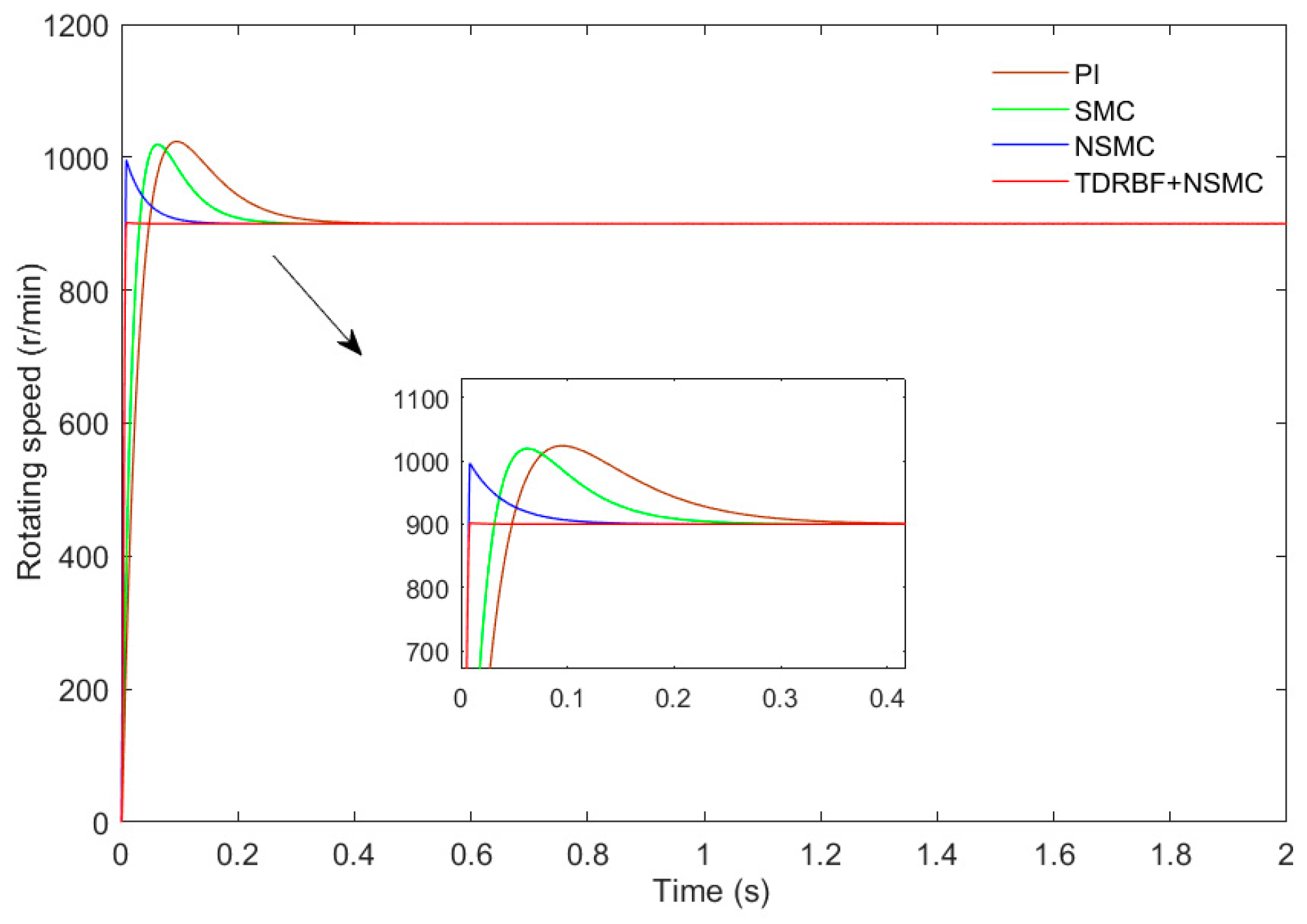
  • The simulation running time is 2 s, the initial motor speed is 900 r/min, and the PMSM is started with a constant load of 10 N∙m. In order to better compare with traditional control, the PI, SMC (based on the traditional exponential approach to law), NSMC, and NSMC methods based on the TD and RBF neural network are used in this paper. The motor speed curve with three control methods is shown in Figure 5.
Figure 5 compares the motor feedback speed curves under the four control methods. It can be seen from the enlarged figure that among the three control methods, the TDRBF-SMC control and SMC control have similar response speeds; through comparison, it can be found that the TDRBF-NSMC control has a faster convergence speed, the PMSM can reach a stable speed state in 0.008 s, the NSMC control takes 0.185 s, the SMC control takes 0.325 s, the PI control takes 0.45 s. At the turning point, the three control methods have overshoot: the overshoot of the PI control is 13.67%, the overshoot of the SMC control is 12.58%, the overshoot of the NSMC control is 10.67%, and the overshoot of the TDRBF-NSMC control is significantly reduced to 0.17%. In general, the speed convergence of the system based on TDRBF-NSMC control is faster, and the overshoot is smaller, which shows that the starting control effect is better.
2.
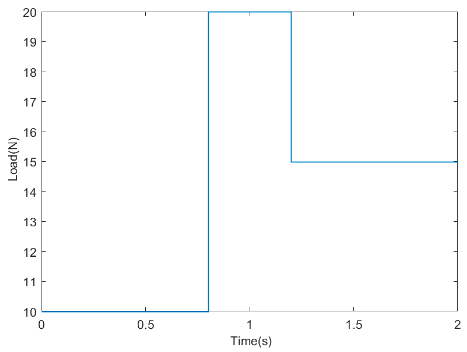
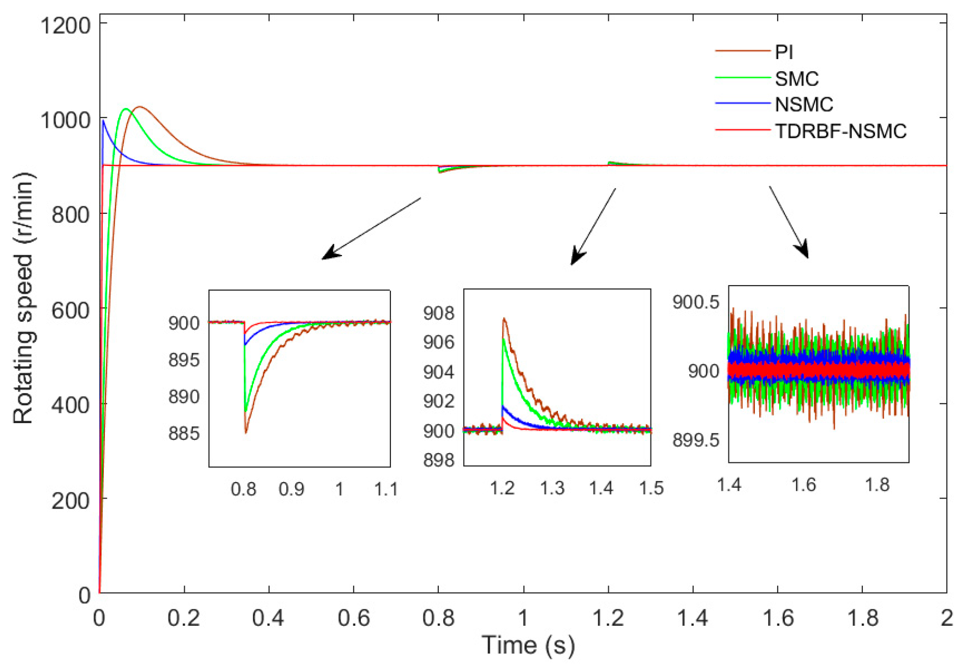
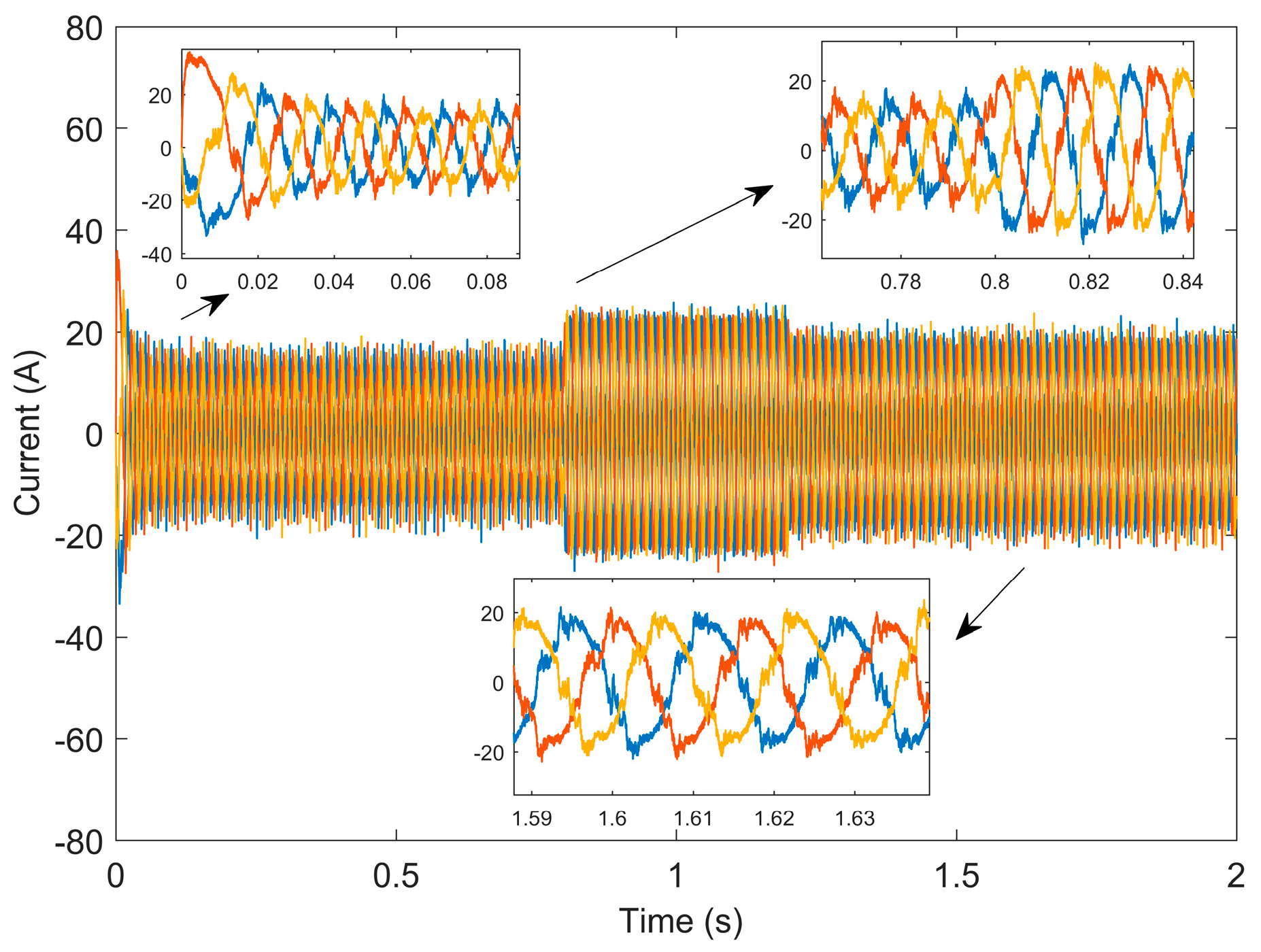
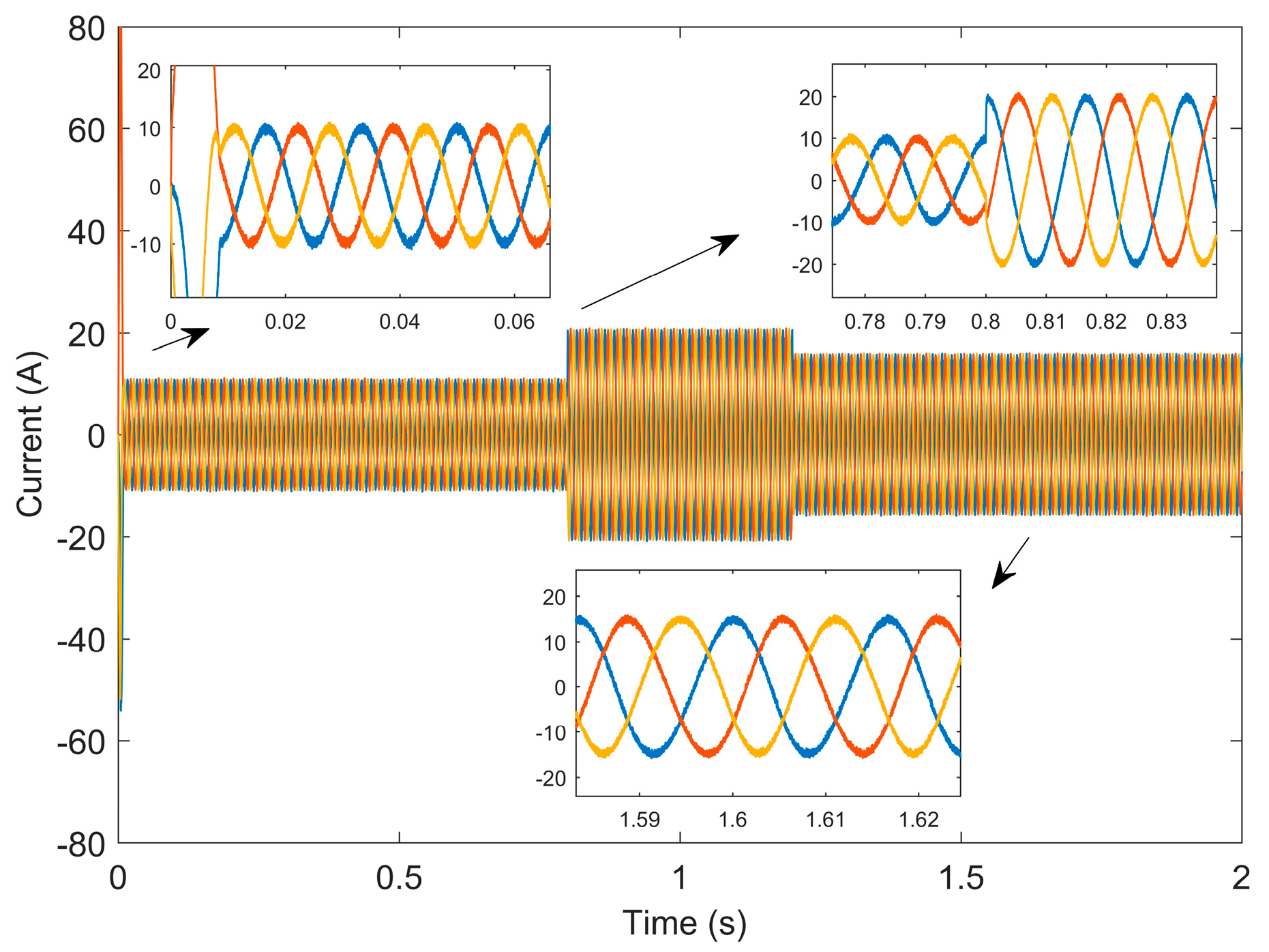
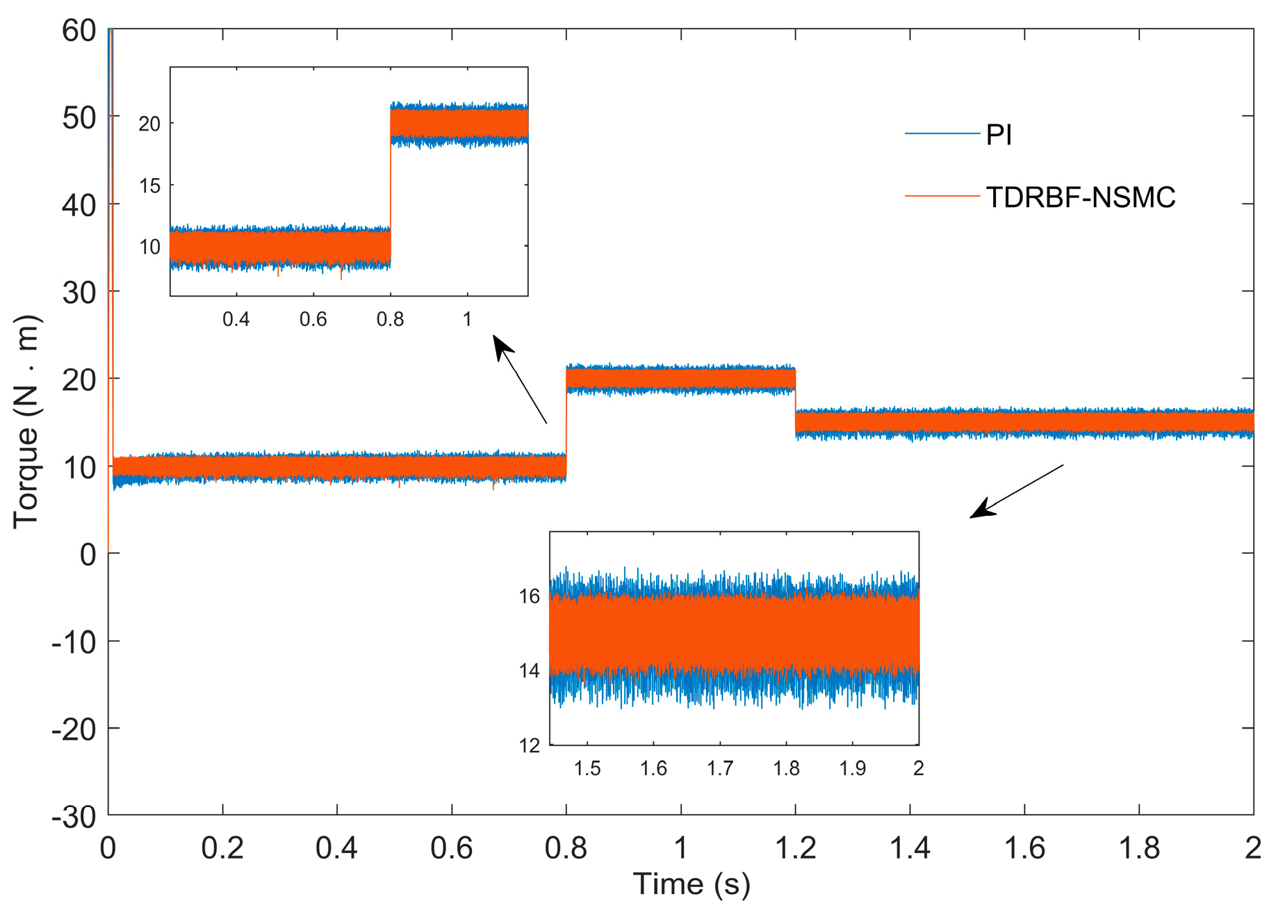
To verify the response speed and tracking ability of the new control method in the presence of load disturbance when the load disturbance exists. The simulation running time is 2 s, the initial speed of the electrode is 900 r/min, the PMSM is started when the load is 10 N∙m, and the load is suddenly increased to 20 N∙m in 0.8 s, runs to 1.2 s, and suddenly reduces the load to 15 N∙m. The load variation curve is shown in Figure 6. The comparison of the motor speed curves using the four control methods is shown in Figure 7.
The response time and overshoot when the load is suddenly increased or decreased are almost the same as the situation with a constant load in the previous simulation condition 1, which is not explained too much here. From the enlarged view, at the sudden load increase of 0.8 s and the sudden load reduction of 1.2 s, the NSMC control, and TDRBF-NSMC control return to the stable state significantly faster than the PI control: the PI control needs 0.26 s to return to the stable state, the SMC control needs 0.22 s to return to the stable state, The NSMC control needs 0.11 s to return to the steady state, and the TDRBF-NSMC control needs 0.043 s to return to the steady state. The TDRBF-NSMC control speed curve has the smallest deviation from the given trend, the NSMC control speed curve has a small deviation from the given trend, and the PI control speed curve has the largest deviation from the given trend. When the motor speed reaches a stable speed, the average speed range undue the PI control is 899.7~900.3 r/min, and the maximum speed fluctuation amplitude is about 0.45 r/min. The average speed range under the SMC control is 899.7~900.23 r/min, and the maximum speed fluctuation amplitude is about 0.28 r/min. The average speed range under the NSMC control is 899.9~900.15 r/min, and the maximum speed fluctuation is about 0.16 r/min. The average speed range under the control of TDRBF-NSMC is 899.95~900.05 r/min, and the maximum speed fluctuation is about 0.07 r/min. Table 2 shows the comparison of the results of two simulation processes: constant load startup and increasing load disturbance. Compared with the traditional exponential reaching law, the control method based on the hybrid reaching law reduces the overshoot by 22 r/min, the velocity decline by 77.1%, and the velocity recovery time by 0.059 s. After the optimization of the new control method proposed in this paper, the overshoot is reduced again by 86 r/min, the speed drop is reduced again by 48.5%, and the speed recovery time is shortened by 0.073 s. It can be seen that the robustness is significantly improved. To sum up, the RBF-NSMC control has stronger accuracy, robustness, and tracking.
Figure 8 and Figure 9 are the waveforms of current changes based on PI control and the TDRBF-NSMC control, respectively. By comparison, it can be seen that the current curve of the TDRBF-NSMC control algorithm is smoother than that of PI control, so the harmonic content of the control algorithm is lower than that of PI control, the operation result is ideal, and the loss of the motor is smaller.
Figure 10 shows the torque response curves of PI control and TDRBF-NSMC control. It is found from the enlarged diagram that the torque ripple of TDRBF-NSMC control is smaller than that of PI control, which reduces the torque ripple by 33%. The control system operates more safely and stably. As a result, the control accuracy and tracking ability of the motor control system are greatly enhanced, and the results are satisfactory.
Figure 11 and Figure 12 show the flux linkage trajectories of PI control and TDRBF-NSMC control. By comparison, it is found that the flux linkage pulsation of TDRBF-NSMC control is significantly smaller than the torque pulsation of PI control, which is closer to a perfect circle.

5. Conclusions

Aiming at the PMSM system, a novel sliding mode control method based on the tracking differentiator and RBF neural network is proposed to improve the control performance of the motor speed control system. Firstly, a new hybrid reaching law is obtained by adding the state variables to the traditional exponential reaching law. Based on this, a new sliding mode velocity controller is designed, which considers the load disturbance and the uncertainty disturbance caused by the change of internal parameters. Secondly, the speediest tracking differentiator is designed to estimate a given speed signal and its derivative to realize the novel sliding mode variable structure algorithm. Finally, RBF neural network is used to approximate the total disturbance of the system in real time to compensate for the influence of uncertain disturbance on the tracking performance of the system. The desired speed signal of the PMSM system under no-load and sudden load increase or decrease conditions is taken as the tracking target of the new sliding mode controller, and the effectiveness and robustness of the proposed sliding mode control method are verified. The results show that the new sliding mode control method presented in this paper has smaller tracking errors and faster convergence speeds, and it can provide reliable support for the stable operation of the control system of the PMSM.

Author Contributions

Investigation, Z.G. and F.H.; methodology, C.Q. and Y.H.; project administration, C.Q. and X.W.; software, Y.H.; writing—original draft, C.Q. and Y.H.; writing—review & editing, Y.H. and X.W. All authors have read and agreed to the published version of the manuscript.

Funding

This work is supported in part by the National Natural Science Foundation of China under Grant 51777127, Liaoning Natural Science Foundation under Grant 2020-MS-240 and 2020-MS-242, Shenyang Young and Middle-aged Scientific and Technological Innovation Talents under Grant RC200192, Liaoning Provincial Department of Education Scientific Research Project under Grant LJKZ1085.

Conflicts of Interest

The authors declare no conflict of interest.

References

  1. Yu, P.; Wang, S.; Yang, J.; Zhang, Y.; Xue, H.; Huang, K. Adaptive reverse thrust robust control strategy for permanent magnet synchronous motor based on gray wolf optimization. Power Syst. Prot. Control 2021, 49, 39–46. [Google Scholar]
  2. Liu, Z.; Miao, S.; Li, W.; Liu, J. Control of Permanent Magnet Synchronous Motor Sensorless Based on Super-twisting Sliding Mode Observer. J. Northeast. Univ. Nat. Sci. 2020, 41, 741–746. [Google Scholar]
  3. Wu, J.; Wu, H. Current Disturbance Compensation Sensorless Control of Permanent Magnet Synchronous Motor. Electr. Mach. Control 2020, 24, 80–86+95. [Google Scholar]
  4. Pan, F.; Yan, G.; Yuan, W.; Qin, G.; Yu, Y. Based on double sliding model of permanent magnet synchronous motor direct torque control. Trans. China Electrotech. Soc. 2018, S2, 427–433. [Google Scholar]
  5. Wang, W.; Wu, J.; Zhang, Y.; Wei, H.; Ge, H. Permanent magnet synchronous motor fuzzy self-tuning adaptive step integral inverse control. Trans. China Electrotech. Soc. 2020, 35, 724–733. [Google Scholar]
  6. Chang, X.; Liu, L.; Cui, R. Non-singular fast terminal variable boundary layer sliding mode control of permanent magnet synchronous motor. J. Xi’an Jiaotong Univ. 2015, 49, 53–59. [Google Scholar]
  7. Gandikot, G.; Dushmanta, K.D. Terminal sliding mode disturbance observer based adaptive super twisting sliding mode controller design for a class of nonlinear systems. Eur. J. Control 2021, 1, 232–241. [Google Scholar]
  8. Nguyen, T.H.; Nguyen, T.T.; Nguyen, V.Q.; Le, K.M.; Tran, H.N.; Jeon, J.W. An Adaptive Sliding-Mode Controller with a Modified Reduced-Order Proportional Integral Observer for Speed Regulation of a Permanent Magnet Synchronous Motor. IEEE Trans. Ind. Electron. 2022, 69, 7181–7191. [Google Scholar] [CrossRef]
  9. Alnami, H.; Pang, C.; Wang, Q. A Novel Sliding Mode Control Method of Interior-Mounted PMSM. In Proceedings of the 2021 IEEE Texas Power and Energy Conference (TPEC), College Station, TX, USA, 2–5 February 2021; pp. 1–6. [Google Scholar]
  10. Zhao, F.; Luo, W.; Gao, F.; Yu, J. Improved sliding mode control of permanent magnet synchronous motor considering sliding mode buffeting and disturbance compensation. J. Xi’an Jiaotong Univ. 2020, 54, 28–35. [Google Scholar]
  11. Heidarpoor, S.; Tabatabaei, M.; Khodadadi, H. Speed control of a DC motor using a fractional order sliding mode controller. In Proceedings of the 2017 IEEE International Conference on Environment and Electrical Engineering and 2017 IEEE Industrial and Commercial Power Systems Europe (EEEIC/I&CPS Europe), Milan, Italy, 6–9 June 2017; pp. 1–4. [Google Scholar]
  12. Zhang, X.; Sun, L.; Zhao, K.; Sun, L. Nonlinear Speed Control for PMSM System Using Sliding-Mode Control and Disturbance Compensation Techniques. IEEE Trans. Power Electron. 2013, 28, 1358–1365. [Google Scholar] [CrossRef]
  13. Shah, P.; Ubare, P.; Ingole, D.; Sonawane, D. Performance Improvement of BLDC Motor Speed Control Using Sliding Mode Control and Observer. In Proceedings of the 2021 International Symposium of Asian Control Association on Intelligent Robotics and Industrial Automation (IRIA), Goa, India, 20–22 September 2021; pp. 247–252. [Google Scholar]
  14. Kashif, M.; Murshid, S.; Singh, B. Adaptive SMC Based DTC of Position Sensorless PMSM Driven Solar PV Water Pumping System. In Proceedings of the 2018 2nd IEEE International Conference on Power Electronics, Intelligent Control and Energy Systems (ICPEICES), Delhi, India, 22–24 October 2018; pp. 765–770. [Google Scholar]
  15. Rascón, R.; Rosas, D.I.; Rodríguez-Quiñonez, J.C. Robust Continuous Control for a Class of Mechanical Systems Based on Nonsingular Terminal Sliding Mode. IEEE Access 2020, 8, 19297–19305. [Google Scholar] [CrossRef]
  16. Zhang, H.; Bu, R.; Yu, G. RBF neural network sliding mode control for ship path tracking. J. Shanghai Marit. Univ. 2021, 42, 7–11. [Google Scholar]
  17. Tang, H.; Zhao, W. Research on parameter self-learning sliding mode control of permanent magnet synchronous motor. Electr. Mach. Control Appl. 2016, 43, 1–7. [Google Scholar]
  18. Van, M. An Enhanced Robust Fault Tolerant Control Based on an Adaptive Fuzzy PID-Nonsingular Fast Terminal Sliding Mode Control for Uncertain Nonlinear Systems. IEEE/ASME Trans. Mechatron. 2018, 23, 1362–1371. [Google Scholar] [CrossRef]
  19. Hu, Q.; Wang, Z.; Cao, L.; Zhang, J. Research on Improved Reaching Law Sliding Mode Control of Permanent Magnet Synchronous Motor Based on Fuzzy Neural Network Optimization. J. Chongqing Jiaotong Univ. Nat. Sci. 2022, 41, 139–144. [Google Scholar]
  20. Lawal, M.O. Tomato detection based on modified YOLOv3 framework. Sci. Rep. 2021, 11, 1447. [Google Scholar] [CrossRef] [PubMed]
  21. Wu, Z.; Xun, P.; Su, H. Research on the control of a naval gun loading mechanism based on RBF neural network adaptive sliding mode control technology. J. Gun Launch Control 2022, 43, 56–61. [Google Scholar]
  22. Roy, A.M. Adaptive transfer learning-based multiscale feature fused deep convolutional neural network for EEG MI multiclassification in brain–computer interface. Eng. Appl. Artif. Intell. 2022, 116, 105347. [Google Scholar] [CrossRef]
  23. Oliveira, T.R.; Estrada, A.; Fridman, L.M. Global and exact HOSM differentiator with dynamic gains for output-feedback sliding mode control. Automatica 2017, 81, 156–163. [Google Scholar] [CrossRef]
  24. Rodrigues, V.H.P.; Oliveira, T.R. Global Adaptive HOSM differentiators via monitoring functions and hybrid state-norm observers for output feedback. Int. J. Control 2018, 91, 2060–2072. [Google Scholar] [CrossRef]
  25. Liu, J. RBF Neural Network Control for Mechanical Systems: Design, Analysis and Matlab Simulation; Tsinghua University Press: Beijing, China, 2018; pp. 106–111. [Google Scholar]
Figure 1. Motor control system based on the RBF neural network.
Electronics 11 03135 g001
Figure 2. Comparison of input signal and output tracking signal.
Electronics 11 03135 g002
Figure 3. Approximate differential signal output.
Electronics 11 03135 g003
Figure 4. Block diagram of PMSM control system with TD and RBF-SMC speed controller.
Electronics 11 03135 g004
Figure 5. Motor speed curves based on four control methods at constant load.
Electronics 11 03135 g005
Figure 6. Load variation curve.
Electronics 11 03135 g006
Figure 7. Motor speed curves based on four control methods during sudden load changes.
Electronics 11 03135 g007
Figure 8. Current variation waveform of the PI.
Electronics 11 03135 g008
Figure 9. The current variation waveform of the TDRBF-NSMC.
Electronics 11 03135 g009
Figure 10. The torque response curves of two control algorithms.
Electronics 11 03135 g010
Figure 11. The PI control flux trajectory.
Electronics 11 03135 g011
Figure 12. The TDRBF-NSMC control flux trajectory.
Electronics 11 03135 g012
Table 1. The parameters of the PMSM.
The ParameterValue
The   stator   resistance   R / Ω 0.0918
Magnetic   chain   ψ / w b 0.1688
D   axis   inductance   L / m H 0.000975
Q   axis   inductance   L / m H 0.000975
Number   of   pole   pairs   p n 4
The   moment   of   inertia   J / kg m 2 0.003945
Coefficient   of   viscous   friction   kg / s 0.0004924
Table 2. Comparison of data under constant load start and increasing load perturbation.
Compare the ItemPISMCNSMCTDRBF-NSMC
Overshoot volume/%13.6712.8710.670.17
Speed decrease/%1.671.440.330.17
Speed recovery time/s0.260.2230.1160.043
Publisher’s Note: MDPI stays neutral with regard to jurisdictional claims in published maps and institutional affiliations.

