Article

Multi-Motor Cooperative Control Strategy for Speed Synchronous Control of Construction Platform

1
School of Information and Communication Engineering, Hainan University, Haikou 570228, China
2
China National Chemical Engineering NO. 13 Construction Co., Ltd., Cangzhou 061000, China
3
College of Civil Engineering and Architecture, Hainan University, Haikou 570228, China
*
Authors to whom correspondence should be addressed.
These authors contributed equally to this work.
Electronics 2022, 11(24), 4162; https://doi.org/10.3390/electronics11244162
Submission received: 3 November 2022 / Revised: 4 December 2022 / Accepted: 9 December 2022 / Published: 13 December 2022

Abstract

:
Barrel-type structures are ubiquitous in industry and life. A novel construction platform of barrel-type structures is introduced, and it involves a multi-motor system. The synchronous control of multiple motors has great importance. To guarantee the high precision, high stability, and fast response for the collaborative control of multiple motors, this paper proposes a multi-motor cooperative control strategy. Firstly, a speed synchronization control structure between multiple permanent magnet synchronous motors (PMSM) is designed by way of the mean coupling control structure. Then, the conventional PID controller is improved by machine learning. Moreover, a radial basis function neural (RBF) network is introduced to the conventional PID algorithm for system identification processing, and the gradient descent algorithm is used for parameter updating. An improved variable speed integral term is introduced into the integral term of the conventional PID algorithm to eliminate the error as soon as possible. Finally, it is verified via numerical simulation experiments that show the multi-motor cooperative control strategy has high anti-interference ability and robustness.

1. Introduction

Barrel-type structures are very common in industry and life, such as elevated bridge piers, TV towers, chimneys, cooling towers, grain silos, and crude oil storage silos, etc. These structures are made of reinforced concrete and need to be constructed with the help of construction platforms [1]. There are many kinds of barrel structures with different section shapes, and they are characterized by towering heights and thin walls. The construction platform of the cylinder structure is a complicated spatial three-dimensional structure. The complicated spatial structure increases the danger of the construction process of the cylinder structure. Once the construction platform of the cylinder structure encounters an accident, the consequences are very serious. For example, the collapse of the construction platform of the cooling tower project in a power plant in Yichun City caused many deaths and injuries [2].
Currently, conventional construction platforms include scaffold construction platforms, hydraulic sliding platforms, and electric lifting platforms. However, the scaffold construction platform is time-consuming and expensive. Moreover, it cannot be used for the construction of towering structures [3,4]. The hydraulic sliding platform requires a large number of steel pipes buried in barrel-type structures, which cannot be recovered after the construction. The hydraulic sliding platform is costly and less efficient to lift. At the same time, the hydraulic sliding platform involves a large number of jacks, which requires high synchronization and coordination. The conventional electric sliding platform needs to install a large number of through-wall anchors in the structure, which leads to a significant reduction in the waterproofing effect of the structure. Meanwhile, the conventional electric sliding platform involves many driving devices. Failure of synchronization of the driving devices results in center drift and torsion [5].
In response to the above limitations, a novel construction platform for barrel-type structures was jointly designed by Hainan University and China National Chemical Engineering NO. 13 Construction Co., Ltd. It is introduced in detail later. The novel construction platform does not require the use of steel pipes buried in the barrel-type structures. It also does not require through-wall anchors. Moreover, it can be reused and has high lifting efficiency. The novel construction platform involves multiple motors. A motor synchronization control system is necessary to guarantee the safety and reliability of the construction process.
Permanent magnet synchronous motors, due to their simple structure, high power density, wide speed range, fast response, and good reliability, have been increasingly used in automobiles, unmanned aircraft, servo control, and computer numerical control (CNC) machine tools. In many engineering controls, the traditional motor servo system is composed of a single motor. However, it has difficulties for the optimization of the control strategy relying solely on a single motor. Thus, some researchers devote themselves to the research of multi-motor cooperative control systems [6]. Some scholars have conducted research on the controller and some algorithm design, especially in the field of PID control and artificial neural networks [7,8]. There are some factors affecting the synchronous control performance of a multi-motor cooperative control system. For example, the electrical parameters of each motor are not exactly the same. There are also some differences in the operating conditions of each motor, such as the different working loads for each motor. Moreover, motors may be subject to different external disturbances, such as temperature, humidity, magnetic field, dust, and other factors, that lead to changes in the electrical parameters. The existence of multiple factors leads to the different performance of each motor in the operation process, which has a great impact on the cooperative control of multi-motor systems [9].

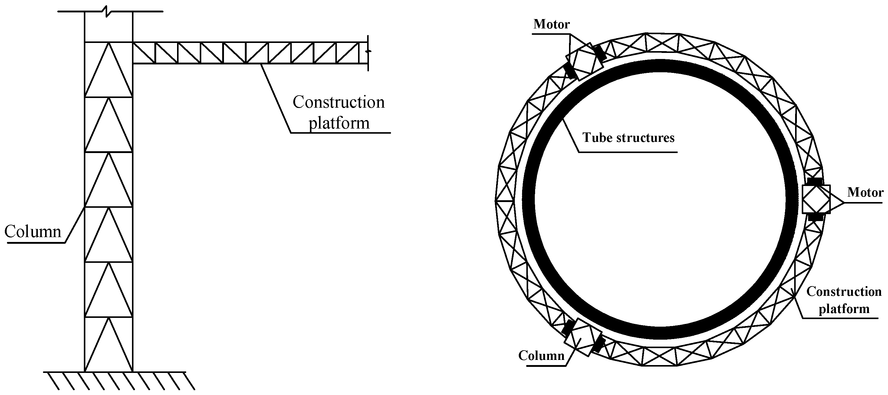
1.1. Technical Concepts

At present, the research on cooperative control technology mainly focuses on two aspects of synchronous control structure and synchronous control algorithm. The control structure is mainly divided into two types. One is the uncoupled control, where each control unit does not interfere with others. The other type is the coupled control where each control unit affects and interacts with others. Uncoupled control methods include parallel control and master–slave control. The coupled control methods include cross-coupling control, adjacent cross-coupling control, deviation coupling control, and mean coupling control [10]. The cross-coupling control was first proposed by Koren [11]. The cross-coupling control realizes the mutual coupling between two motors. However, it is not applicable to systems with more than three motors, which has great limitations in industrial applications. Shih proposed an adjacent cross-coupling control strategy applicable to systems with more than three motors. When the output of one motor in the system changes due to external disturbances, the neighboring motors can be used to maintain the performance between motors. However, the global coupling compensation of adjacent cross-coupling control encounters difficulties. In response to the above limitation, a deviation-coupling control strategy can be used, and the deviation-coupling control has better performance in the global compensation. However, the existence of multiple speed compensators leads to a large computational cost in the deviation coupling control strategy. Considering the excellent global compensation of deviation-coupled control and the low computational cost of adjacent cross-coupling, some scholars have proposed the mean-coupling synchronous control strategy [12]. The mean-coupling control takes the tracking error of a single motor and the mean of the multi-motor tracking error as the compensation of the speed synchronization control, which ensures the global compensation and computational cost of the coupling.
In the study of multi-motor synchronous control algorithms, proportion integration differentiation (PID) controllers are effective in automatic control systems with the advantages of simple algorithm structure and easy implementation. At the same time, conventional PID control has some shortcomings, such as low algorithm control accuracy, the need for manual parameter optimization, and poor self-adaptability. Thus, the conventional PID controllers have difficulties in meeting the requirement of high-precision control. To improve the conventional PID controller, Sun Meng designed the fuzzy adaptive PID control algorithm. Diwen Xu designed a pigeon-inspired swarm algorithm to rectify the PID parameters for the synchronous demand of a flexographic printing machine. Hou Qishan combined a fuzzy algorithm, PID algorithm and particle swarm algorithm to solve the multi-motor cooperative control problem involved in the active threading plate of a weaving machine. FeiFei Wu combined fuzzy control and a radial basis function (RBF) neural network algorithm for the synchronous control system. The mentioned PID controller has poor anti-interference ability and slow convergence speed, which cannot meet the working needs of the construction platform of barrel-type structures. The construction platform of barrel-type structures has complicated working conditions during construction, high impact of external loads on the platform, and high interference [13,14].

1.2. Main Contribution

To achieve cooperative control among multiple motors in the construction platform of barrel-type structures, this paper proposes a multi-motor mean-coupling cooperative control method based on an RBF neural network considering vector control theory. A novel RBF-PID controller is designed. In this novel controller, a radial basis function (RBF) neural network is introduced for system identification processing, and a gradient descent algorithm is used for parameter updating, which can find the optimal solution faster, eliminate the static difference effectively, and improve the control accuracy. Then, MATLAB is used for experimental verification. Experiments are designed to compare the tracking and synchronization control effects of the permanent magnet synchronous motor under the two strategies of conventional PID and RBF-PID.

1.3. Organization

The rest of this paper is organized as follows: Section 2 reviews a construction platform that is related to the multi-motor system. Section 3 reviews the basic formulations of a single motor. Section 4 is devoted to a multi-motor speed synchronous control structure. Section 5 describes the RBF neural network PID controller developed for high accuracy and synchronization in the motor control system. Section 6 discusses the reliability and effectiveness of the synchronous control strategy via experimental simulations. Finally, concluding remarks are provided in Section 7.

2. Related Work

The main content included here is the design of the construction platform of barrel-type structure. The construction platform of the barrel-type structure was jointly developed by Hainan University and China National Chemical Engineering NO. 13 Construction Co., Ltd., and it mainly consists of five systems: support system, platform system, plank system, lifting system, and foundation system. The supporting system consists of supporting columns and wall support. The main function of the supporting column is to bear the vertical load of the whole construction platform, and the wall support is to restrain the horizontal offset of the supporting column. The platform system consists of a truss, and it can be lifted up and down along the supporting columns under the drive of multiple motors. The plank system is laid on the truss of the platform system. The plank system allows the stacking of construction tools and materials, and it also serves as a working site for the construction personnel. The lifting system is arranged on both sides of the platform and the supporting columns, and the lifting system is composed of multiple permanent magnet synchronous motors (see Figure 1). The foundation system consists of recyclable pile foundations, and it bears the upper load.
This construction platform can be built in a short time. It does not need to bury a large number of steel pipes in the structure, nor does it need to install a large number of through-wall anchors. This construction platform can significantly improve the efficiency of the project and ensure the safety and reliability of the construction.

3. Working Principle of Single Motor

3.1. Mathematical Model

The permanent magnet synchronous motor is a complicated system with strong coupling and multi-variables. To simplify the analysis process, some assumptions are made. The air-gap magnetic field of the motor is uniform and sinusoidally distributed. The resistance and inductance of the winding are constant. The influence caused by the saturation of the magnetic circuit is ignored, and the hysteresis and eddy current losses are also ignored. The effect of the stator slot is ignored [15,16]. The mathematical model of the permanent magnet synchronous motor is shown in Figure 2.
In the above figure, A A , B B , C C are the three-phase windings of the stator, and their axial directions are 120° different from each other in the spatial phase, and they are evenly and symmetrically distributed, which together constitute the ABC three-phase stationary coordinate system. The α - β axis is the two-phase stationary coordinate system of the permanent magnet synchronous motor stator, in which the α -axis coincides with the A-axis, and the β -axis leads the α -axis by 90°. ψ f is the flux linkage of the motor rotor, ω e is the electrical angular velocity of the motor rotor, and θ is the phase A between ψ f and the stator. For the angle between the axis directions of the coils, the d axis lags the q axis by 90°, and the d axis and the rotor flux linkage ψ f are superimposed to construct a d-q two-phase rotating coordinate system, which rotates with the permanent magnet synchronous motor rotor at the electrical angular velocity ω e [17,18].
PMSM is a complex system with strong coupling and multi-variables. It is difficult to analyze it from the A B C natural coordinate system. Therefore, in order to reduce the complexity of its mathematical model to a certain extent and facilitate analysis and research, the coordinates are introduced here. Transform the theory, transform it into the dq synchronous rotating coordinate system for analysis, and make it have the form of the mathematical model of the DC motor, which can greatly simplify the difficulty of the analysis. The process of transforming from the A-B-C coordinate system to the α - β coordinate system is called a Clark transformation, and vice versa is the Clark inverse transformation; the process of transforming from a α β to dq coordinate system is called Park transformation, and vice versa is Reverse-Park transformation (R-Park) [19].
Figure 3 is a schematic diagram of coordinate transformation, in Figure 3a: at any time, the variable V A B C in the ABC coordinate system can be decomposed by the vector and projected into the α - β coordinate system, and the composite vector of the two is the same. The Figure 3b: the projection of the vector V i on the α - β coordinate axis and the d-q coordinate axis after the vector decomposition is V α β and V d q .
The description of the mathematical model of the permanent magnet synchronous motor includes the voltage equation, the flux linkage equation, and the torque equation, etc. Through the mathematical model established above and the idea of coordinate transformation, the stator voltage balance equation in the synchronous rotating coordinate system can be obtained as:
u d = r i d + d ψ d d t ω ψ q u q = r i q + d ψ q d t + ω ψ d
where u d , u q are the d-axis and q-axis voltage components of the motor. r is the stator resistance of the motor. i d , i q are the d-axis and q-axis current components of the motor. ω e is the electric angular velocity of the motor rotor. ψ d, ψ q are the d-axis and q-axis magnetic chain components of the motor.
When the motor convex pole effect is not considered, the equation of the magnetic chain is as follows.
ψ d = L d i d + ψ f ψ q = L q i q
where L d and L q are the d-axis and q-axis inductances of the motor, respectively. ψ f is the rotor magnetic chain.
Using the principle of equal amplitude transformation, the electromagnetic torque equation of the permanent magnet synchronous motor is obtained, as shown below.
T e = p n ψ d i q ψ q i d
Substituting the flux linkage Equation (2) into the torque Equation (3), we can obtain the following.
T e = p n ψ f i q + L d L q i d i q
where T e is the electromagnetic torque of the permanent magnet synchronous motor, p n is the number of pole pairs of the stator winding of the motor. For the hidden pole permanent magnet synchronous motor, due to L d = L q , in order to make the control more simple and direct, the control strategy of i d = 0 was adopted. The electromagnetic torque equation can be simplified as:
T e = p n ψ f i q
The equations of mechanical motion of the motor are as follows.
T e = T L + B ω + J d ω d t
Substitute (5) into (6) to obtain the following.
i q = T L + B ω + J d ω d t T L + B ω + J d ω d t p n ψ f p n ψ f
where T L is the load torque of the motor, ω is the mechanical angular velocity of the motor, ω = ω e / p n , J is the rotational inertia of the motor, B is the friction factor of the motor.
Through the above theoretical analysis and formula derivation of a permanent magnet synchronous motor, it is simple to find that the speed control of the motor is essentially the control of electromagnetic torque whose amplitude depends on the q-axis current. The independent control of excitation current and torque components can be realized by vector control technology.

3.2. Vector Control System

The basic idea of vector control is to decouple three phases (i.e., the stator current, magnetic chain, and mechanical torque) into a two-phase coordinate system by Park transformation and Clark transformation. As a result, motor speed control can be achieved by controlling the torque current i d and excitation current i q , respectively. The vector control structure of the permanent magnet synchronous motor is shown in Figure 4.
Figure 4 shows the vector control structure. The outer loop is the speed loop, and the inner loop is the current loop. The dual closed-loop realizes the real-time tracking control of motor speed and current, respectively. In the figure, ω r is the set input speed, ω is the output mechanical angular speed of the motor (multiplied by 30/ π is the speed, which is also referred to as the speed in the text for the convenience of explanation), and e is the input and feedback The deviation between the output speeds, i q * , i d * are the adjustment amounts of the current component. The three current phases A, B, and C of the motor stator are mapped to the d q via a rotating coordinate system to obtain i d , i q . The current loop is reasonably controlled according to the deviation signal to obtain u d , u q . The voltage signal is processed through space vector pulse width modulation (SVPWM) to control the inverter, which realizes the vector control of PMSM [20].

4. Multi-Motor Speed Synchronous Control Structure

The construction platform involves multiple permanent magnet synchronous motors (see Figure 1). In order to ensure the coordination of multiple motors, a mean-coupled synchronous control structure is designed in this paper (see Figure 5). The synchronization error is obtained via calculating the difference value between the tracking error of a single motor and the mean value of the multi-motor tracking error. The designed synchronous control structure divides the original controller into two independent controllers, which are used to process the tracking error signal and the synchronization error signal, respectively. This method can compensate the motor according to the tracking error and synchronization error at the same time, which can improve the response speed of the control system and enhance the system’s robustness.
The i-th motor tracking error is defined as the following equation.
e i ( t ) = ω i ( t ) ω r ( t )
where ω i ( t ) is the output speed of the feedback of the i t h motor at time t, ω r ( t ) is the desired speed at time t. Where i = 1 , 2 , 3 , and the coupled synchronous control structure can be used for multiple motors. This article uses three motors to explain.
The synchronization error of the i-th motor is defined as follows.
e s y i ( t ) = ω i ( t ) i = 1 n ω i ( t ) / n = ω i ( t ) ω r ( t ) i = 1 n ω i ( t ) / n + ω r ( t ) = e i ( t ) [ i = 1 n ω i ( t ) / n ω r ( t ) ] = e i ( t ) [ i = 1 n ω i ( t ) n ω r ( t ) ] / n = e i ( t ) i = 1 n e i ( t ) / n
The computational cost of the mean-coupled control structure is much lower than other synchronous control structures, which improves the global compensation capability of the control system. The above mean-coupled control structure can ensure the synchronization between multiple motors.
In order to realize the synchronous control strategy for the platform of the barrel-type structure, the design of the PID controller is also required, and it is the core of the whole system. In this paper, the RBF neural network is introduced into PID controller for parameter optimization.

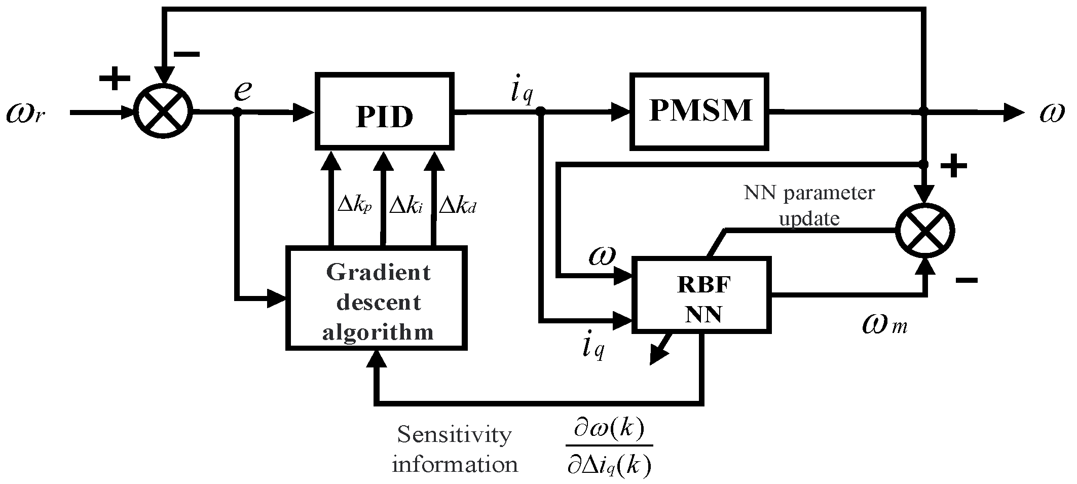
5. Improving PID Controller via RBF Neural Network

The radial basis function (RBF) neural network is now commonly used in function approximation, image processing, pattern recognition and prediction, and control systems because of its simple structure, fast learning speed, and fast convergence, etc. It can also effectively avoid the local minimal value problem. In this paper, we apply an RBF neural network to a synchronous motor control system to improve the accuracy of real-time motor control.

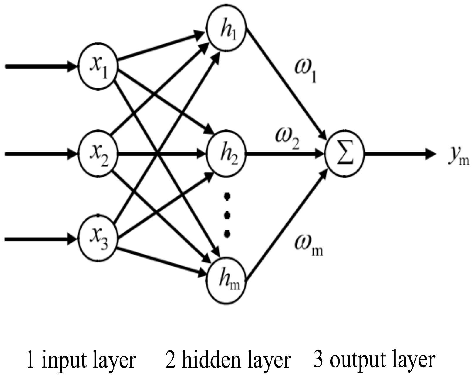
5.1. RBF Neural Network Model

The RBF neural network contains an input layer, implicit layers and an output layer. The input layer can directly pass the input vector to the implicit layer, where the distance is calculated. Then the output layer is linearly weighted to obtain the output of the network [21,22]. The structure of the RBF neural network is shown in Figure 6.
In the figure, x = [ x 1 , x 2 , x 3 ] T is the input vector of the input layer. h = [ h 1 , h 2 , , h m ] T is the radial basis vector of the hidden layer. w j = [ w 1 , w 2 , , w m ] T is the weight vector between the hidden layer and the output layer, where h j is the Gaussian basis function and m is the number of neuron nodes in the hidden layer.
h j = e | | x c j | | 2 2 b j 2 , j = 1 , 2 , , m
where | | | | is the Euclidean norm, also known as Euclidean distance, c j = [ c j 1 , c j 2 , c j 3 ] T is the center vector of the jth hidden layer neuron node, which can be approximated as a vector of weights between the input layer and the hidden layer, and b j is the width of the jth hidden layer neuron node.
The principle of Equation (10) is shown in Figure 7, and the following figure shows the neuron model with a Gaussian kernel as a radial basis function.
In the figure, b is the threshold value, i.e., the neuron width, and R is the Gaussian-based activation function with the general expression R ( d i s t ) = e d i s t 2 2 b 2 , where d i s t = x c j .
The output of the discriminative network is obtained as the following equation.
ω m = j = 1 m w j h j
The performance indicator function of the discriminator is defined as follows.
J = 1 2 ω ( k ) ω m ( k ) 2
where ω (k) and ω m(k) are the actual outputs of the kth cycle iteration of the system and the discriminative output of the neural network, respectively. A gradient descent algorithm is used to modify the parameters of the RBF network, including the intermediate weights ω j, node centers c j and base width b j . The correction formula is shown below. Weight is updated as follows,
Δ w j ( k ) = η J w j = η ω ( k ) ω m ( k ) h j w j ( k ) = w j ( k 1 ) + Δ w j ( k ) + α w j ( k 1 ) w j ( k 2 )
Node Center is updated as follows,
Δ c ji ( k ) = η J c ji = η ω ( k ) ω m ( k ) w j h j x j c ji b j 2 c ji ( k ) = c ji ( k 1 ) + Δ c ji ( k ) + α c ji ( k 1 ) c ji ( k 2 )
The base width parameter is updated below,
Δ b j ( k ) = η J b j = η ω ( k ) ω m ( k ) w j h j | | x c j | | 2 b j 3 b j ( k ) = b j ( k 1 ) + Δ b j ( k ) + α b j ( k 1 ) b j ( k 2 )
where η is the learning rate and α is the momentum factor.
The Jacobian matrix (that is, the sensitivity information of the output of the controlled object to the input control information) algorithm is as follows,
ω ( k ) Δ i q ( k ) ω m ( k ) Δ i q ( k ) = j = 1 m w j h j c j i Δ i q ( k ) b j 2
where i q ( k ) is the input of the controlled object, Δ i q ( k ) is the difference between the previous input of the controlled object and the input of the next step, that is, the input increment.

5.2. Pid Tuning Principle

The diagram of the PID adaptive control structure based on an RBF neural network is shown in Figure 8 [23].
In Figure 8, ω r and ω are the system input and output, e is the deviation, i q is the output of the PID controller, Δ k p , Δ k i , and Δ k d are the three parameter increments of the PID, and ω m is the discriminative output of the RBF neural network. The RBF neural network is used here as a discriminator to approximate the PMSM model. It can obtain the input and output sensitivity information (Jacobian information) of the controlled object PMSM. Then, a gradient descent algorithm is used to perform a minimal value search to obtain the variation of the three PID parameters. The variation can be passed to the PID controller for online parameter adjustment. For the training of the neural network, we use online training, namely adaptive learning. We do not need to prepare a large number of data sets in advance to train the network model. We use the data generated in the actual test to train the neural network. With the real-time data, the model will be updated continuously in operation. Here, the real-time training data of the neural network comes from the input and output of the controlled object (permanent magnet synchronous motor).
In this paper, the incremental PID algorithm is used, and the control error is shown below.
e ( k ) = ω r ( k ) ω ( k )
where ω r ( k ) is the desired value and ω ( k ) is the system output speed, k is the number of iterations. The three inputs of the PID controller are shown as follows.
X ( 1 ) = e ( k ) e ( k 1 ) X ( 2 ) = e ( k ) X ( 3 ) = e ( k ) 2 e ( k 1 ) + e ( k 2 )
The output of the incremental PID control algorithm is obtained as follows.
i q ( k ) = i q ( k 1 ) + Δ i q ( k ) Δ i q ( k ) = k p [ e ( k ) e ( k 1 ) ] + k i e ( k ) + k d [ e ( k ) 2 e ( k 1 ) + e ( k 2 ) ]
The neural network performance metric function is given in the following equation.
E ( k ) = 1 2 e 2 ( k )
The gradient descent algorithm is then used to obtain the adjustment amounts of k p , k i , and k d , which are shown in the following equation.
Δ k p = η E k p = η E ω ( k ) ω ( k ) Δ i q ( k ) Δ i q ( k ) k p = η e ( k ) ω ( k ) Δ i q ( k ) X ( 1 ) Δ k i = η E k i = η E ω ( k ) ω ( k ) Δ i q ( k ) Δ i q ( k ) k i = η e ( k ) ω ( k ) Δ i q ( k ) X ( 2 ) Δ k d = η E k d = η E ω ( k ) ω ( k ) Δ i q ( k ) Δ i q ( k ) k d = η e ( k ) ω ( k ) Δ i q ( k ) X ( 3 )
where ω ( k ) Δ i q ( k ) is the Jacobian information fed back by the PMSM of the controlled object, which can be obtained through the identification of the RBF neural network, see Formula (16).

5.3. Improvement of the Integral Term Based on Variable Speed Integration

In the conventional PID control algorithm, the integration coefficient ki is constant and cannot be adjusted dynamically. The integration is introduced to eliminate static differences and enhance the stability of the system. Moreover, when the PID integral term is over-accumulated, it often leads to oscillation of the system. The accumulation of integral terms usually occurs when the system deviation is large, such as the motor startup phase and large load disturbance. Thus, it is necessary to improve the integration term. The integration rate can be adjusted according to the system deviation via the variable speed integration method, which accelerates the integration rate when the deviation is small and slows down the integration rate when the deviation is large.
To overcome the above disadvantages, the variable speed integration method is improved. The integration term is stabilized at a relatively small value. The value of the integration term does not need to be adjusted to avoid the generation of integration saturation. The integration term is adaptively regulated by the RBF neural network when the system deviation is in the normal range. The algorithm is described as follows.
k i = k 0 e k > A k 0 + Δ k i B e k A k T e k < B
where k 0 is the initial value set by the integration term, k T is the maximum value under the optimal effect of the system set by the integration term, Δ k i is the increment of the integration term provided by the RBF neural network, and A and B are the threshold values set according to the control object.

6. Performance Evaluation

In this section, the effectiveness and reliability of the synchronization control strategy proposed in this paper are verified through experimental simulation. In order to describe the analysis steps more clearly, the flow chart of the whole system is drawn, as shown in Figure 9.

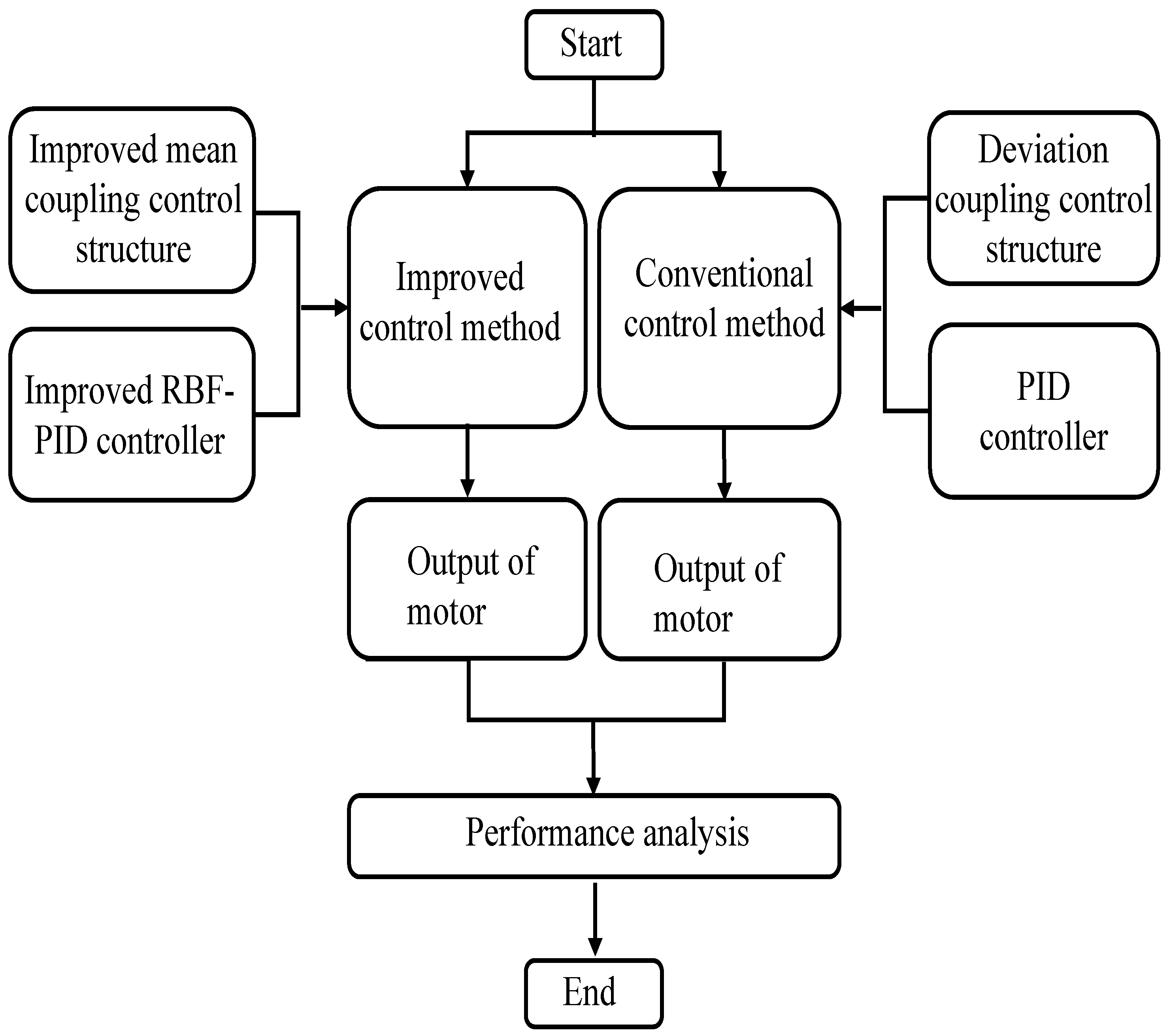
6.1. Experimental Method

Firstly, three permanent magnet synchronous motors were selected and a multi-motor mean-coupled cooperative control model based on an improved PID controller was built on the MATLAB/Simulink platform. Then, experimental simulations were performed and compared with the deviation-coupled control method based on a conventional PID controller. Three identical motors were set up in the experiment, and the main motor parameters were set as follows, rated voltage U = 560 V, stator resistance R s = 0.11 Ω , stator d-axis inductance L d = 0.00092 H, stator q-axis inductance L q = 0.00102 H, magnetic chain φ f = 0.1119 Wb, number of pole pairs P n = 4 , damping factor F = 0.0002 N·m·s, rotational inertia J = 0.0016 kg·m 2 .
The improved PID controller was written using S-functions, a highly flexible high-level function module in Simulink that can be used to describe the behavior patterns of dynamic systems. We can construct a specific S-function by writing the M language.
After extensive simulation experiments, the control parameters of this multi-motor control system were finally determined. The parameters related to the improved PID controller in this paper are as follows: initial values of PID parameters, k p = 0.15 , k i = 6 , k d = 0 , system sampling time T s = 0.000008 s, integration threshold A = 150 , B = 40 . The parameters of the conventional PID controller are as follows: k p = 0.06 , k i = 3.5 , and k d = 0 . The relevant parameters of the RBF neural network are shown in Table 1.

6.2. Simulation and Numerical Analysis

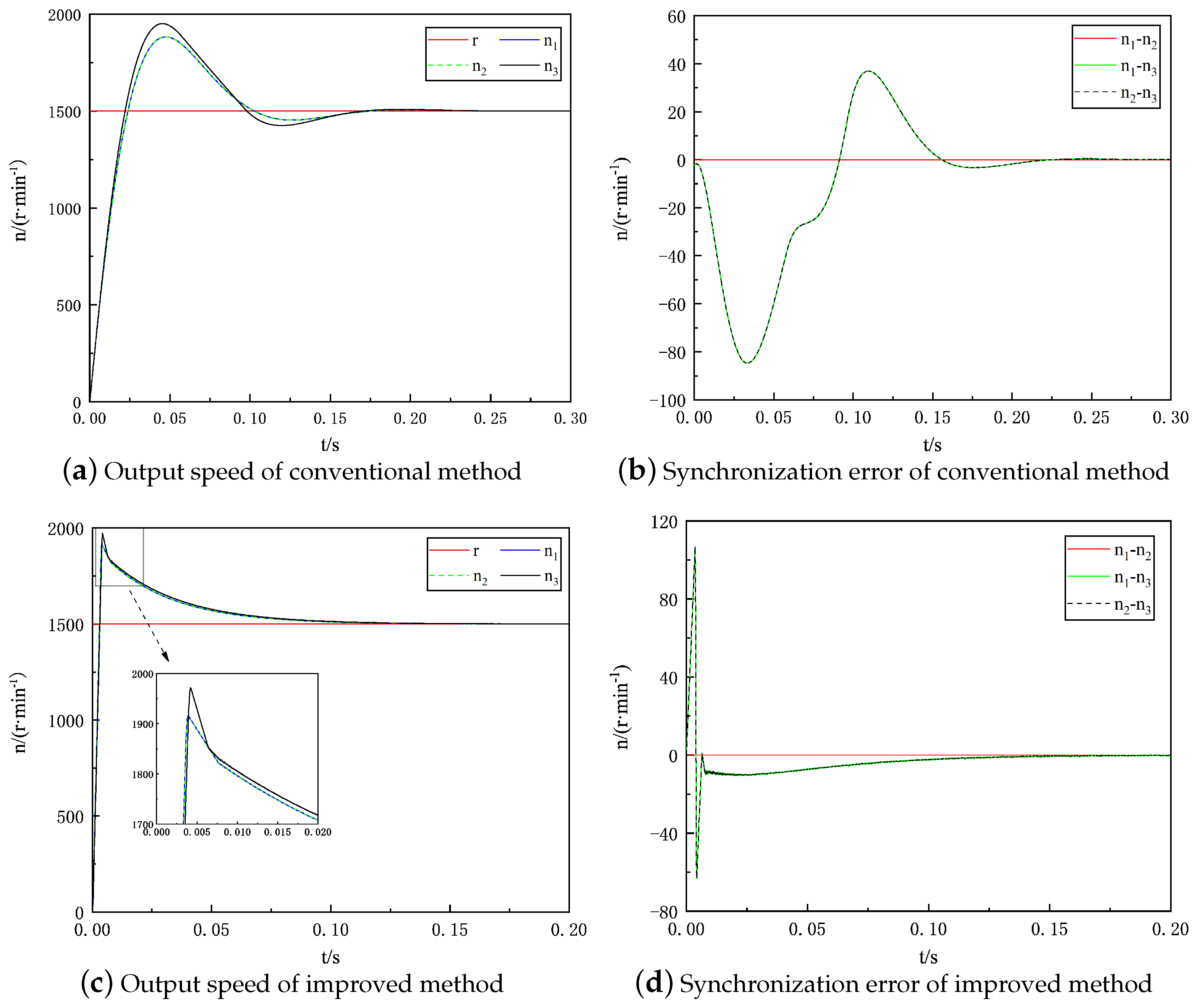
6.2.1. Comparison of Motor Starting Performance with Loading

In the simulation, the load of the construction platform is 150 KN. The platform is divided into three fan-shaped parts. Each part is powered by two motors. Thus, each motor needs to provide at least 25 KN. The motor and reducer are connected directly. The reduction ratio is set as 60:1. The sprocket radius is set as 0.1 m. The motor speed is set as 1500 r/min. The motor loss is about 20%. The power of the permanent magnet synchronous motor in the simulation experiment is about 10 KW, and the torque is about 45 N·m. The main calculation equation involved is as follows.
T = 9550 N / P
where T is torque, N is speed, and P is power.
The motor speed is given as 1500 r/min, the simulation time is 0.3 s, and the initial loads of motor 1, motor 2 and motor 3 are set as 45, 45 and 50 N·m. That is, the loads of motor 1 and motor 2 are the same, and the load of motor 3 is greater than the other two motors. This is reasonable because during the construction process of the barrel-type structure, each motor may be subjected to different loads due to different working conditions.
A comparison of the simulation results of the starting performance of the conventional control method and the improved control method in this paper is shown in Figure 10a,b show the output speed and synchronization error of the conventional control method. Figure 10c,d show the output speed and synchronization error of the improved control method. In the figure, r is the desired output speed. n1, n2, and n3 are the actual output speeds of the three motors. n1−n2 is the speed difference between motors 1 and 2, n1−n3 is the speed difference between motors 1 and 3, and n2−n3 is the speed difference between motors 2 and 3, i.e., the synchronization error.
It can be seen from Figure 10a,c that in the motor startup phase, the rise time of the conventional control method is 0.02 s, and that of the improved control method is 0.005 s. The peak speeds of the two control methods are similar. The maximum response speed of the former is 1975 r/min, while that of the latter is 1945 r/min, and the overshoot is about 30%. However, the adjustment time of the conventional method is about 0.15 s, and that of the improved method is about 0.1 s, which is reduced by about 33%. From Figure 10b,d, it can be seen that the overall synchronization error of the conventional control method is significantly higher than that of the improved control method in the motor starting stage, and the error of the latter mainly exists in the first 0.02 s. The maximum synchronization error of the conventional method is 85 r/min, and that of the improved method is 100 r/min. The adjustment time of synchronization error of the conventional method is about 0.2 s, and that of the improved method is about 0.05 s. The adjustment time is reduced by about 75%. To sum up, in the comparative analysis of motor performance at the initial working stage, the improved control method has a smaller synchronization error and shorter adjustment time than the conventional control method. The performance index of the control system in this experiment is shown in Table 2.

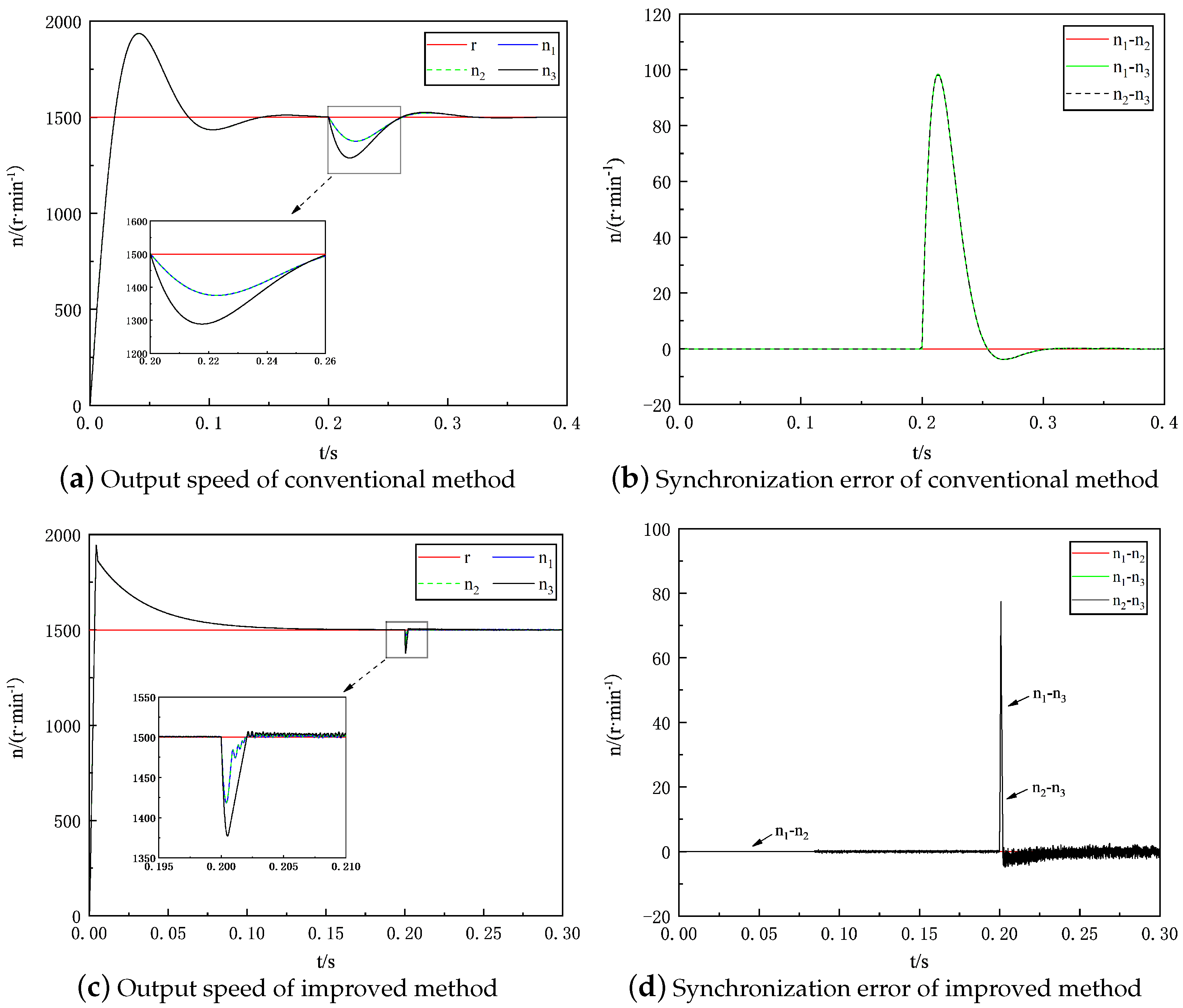
6.2.2. Performance Comparison under the Load Mutation at Steady State

This experiment conforms to the operating conditions described in the above subsections, with a given motor speed of 1500 r/min and a simulation time of 0.4 s. The initial load of all three motors is 45 N·m. Later, a load of 5 N·m is applied to motor 3 at 0.2 s to disturb the system. The output speed and synchronization error after sudden load application in the running steady state using the two methods of motor control are shown in Figure 11.
It can be seen from Figure 11a,c that after a sudden load disturbance, the maximum tracking error of motor 3’s speed (the maximum difference between the output speed and the set speed) in the conventional control method is about 200 r/min, while the maximum tracking error of motor 3’s speed in the improved control method is about 120 r/min, which is about 35% lower than that in the conventional control method. The regulating time of the motor when the load disturbance occurs under the conventional method is 0.06 s, and the improved method is 0.005 s, which is about 90% lower than the conventional method. It can be seen from Figure 11b,d that the maximum synchronization error of the conventional method is about 100 r/min, while that of the improved method is about 80 r/min, with an error reduction of about 20%. The adjustment time of the synchronization error of the conventional method is about 0.07 s, and that of the improved method is about 0.02 s. The performance index of the control system in this experiment is shown in Table 3.
The simulation results clearly show that when the motor encounters load mutation, the motor speed of the improved method changes less than that of the conventional method. Meanwhile, the adjustment time of the improved method is shorter, and the synchronization error between multiple motors is smaller than those of the conventional method. The robustness mentioned here refers to the anti-interference ability of the motor when it is affected by an external load during operation. In other words, when the load on the motor encounters a mutation, the speed of the motor changes as little as possible or the speed of the motor returns to the target speed in a short time.
By comparing the performance of the motor starting with load and the performance of the steady-state load mutation, it can be found that the improved method has better adjustment ability, stronger anti-interference ability than the conventional method, and its performance of multi-motor synchronous control is obviously superior to the conventional method.

7. Conclusions

The multi-motor control system of the construction platform for barrel-type structures requires high motor cooperative control (i.e., high control accuracy and fast response). To address these problems, a multi-motor mean-coupled cooperative control strategy based on an RBF neural network controller is proposed and experimentally verified in this paper. The results show that:
  • The new RBF-PID control algorithm designed can effectively track and control the motor speed and current, thus enhancing the control effect.
  • By constructing the mean-coupled structure and the improved PID controller, the global compensation control of the error of the multi-motor system ensures synchronous convergence, and at the same time, reduces the computational cost.
  • The multi-motor cooperative control scheme designed in this paper has strong dynamic response and regulation capability, anti-interference capability and robustness. The improved control method outperforms the conventional control method in terms of motor overshoot, motor regulation time, maximum synchronization error and the regulation time of the synchronization error.

Author Contributions

All authors made contributions in the discussions, analyses and implementation of the proposed solution. All authors have read and agreed to the published version of the manuscript.

Funding

The authors gratefully acknowledge the financial support received from the Natural Science Foundation of Hainan Province (521QN204); Scientific Research Startup Foundation of Hainan University (KYQD-ZR-21068); Scientific Research Startup Foundation of Hainan University (KYQD-ZR-21067); Key Science and Technology Planning Project of Hainan Province (ZDKJ2021023); Academician Innovation Platform of Hainan Province (YSPTZX202106); Research and development of Green Platform for Barrel-type Structures without Supporting Rods (HD-KYH-2021022) for the completion of this work.

Data Availability Statement

Not applicable.

Conflicts of Interest

The authors declare no conflict of interest.

Abbreviations

The following abbreviations are used in this manuscript:
PIDProportion Integration Differentiation
RBFRadial Basis Function
NNNeural Network
PMSMPermanent Magnet Synchronous Motor
SVPWMSpace Vector Pulse Width Modulation
CNCComputer Numerical Control
DCDirect Current
R-ParkReverse-Park transformation

References

  1. Yang, J.; Chen, L. Safety analysis of slipform system for large silo construction. J. Wuhan Univ. (Eng. Ed.) 2020, 53, 288–292. [Google Scholar]
  2. Synthesis. Focus on the collapse of Jiangxi Fengcheng power plant accident that killed 74 people and injured 2 others. Saf. Health 2017, 1, 6–9. [Google Scholar]
  3. Yan, L. Application of silo slipform operation platform instead of formwork support system technology. Constr. Technol. 2020, 49, 73–75. [Google Scholar]
  4. Gao, J.; Chen, L. Exploration of key technology of sliding mode construction of variable section high pier. Highway 2017, 62, 125–127. [Google Scholar]
  5. Lv, Y.-Y. Dynamic Analysis of Scaffolding under the Walking Load of Construction Personnel; Beijing Jiaotong University: Beijing, China, 2017. [Google Scholar]
  6. Kim, H.; Son, J.; Lee, J. A High-Speed Sliding-Mode Observer for the Sensorless Speed Control of a PMSM. IEEE Trans. Ind. Electron. 2011, 58, 4069–4077. [Google Scholar]
  7. Vinod, J.; Sarkar, B.K. Francis turbine electrohydraulic inlet guide vane control by artificial neural network 2 degree-of-freedom PID controller with actuator fault. Proc. Inst. Mech. Eng. Part I J. Syst. Control Eng. 2021, 235, 1494–1509. [Google Scholar]
  8. Mohamed, I.; Salem, M.F. LFC based adaptive PID controller using ANN and ANFIS techniques. J. Electr. Syst. Inf. Technol. 2014, 1, 212–222. [Google Scholar]
  9. Ge, Y. Research on Multi-Motor Cooperative Control Strategy and Application; Lanzhou University of Technology: Lanzhou, China, 2020. [Google Scholar]
  10. Liu, P. Research on the Control Strategy of Multi-Motor Speed Synchronization Control System; Liaoning University of Engineering and Technology: Fuxin, China, 2017. [Google Scholar]
  11. Qi, D. Research on Multi-Motor Precise Synchronous Control System; Shenyang University of Technology: Shenyang, China, 2018. [Google Scholar]
  12. Yao, W. Research on Multi-Motor Synchronous Control Strategy; Xiangtan University: Xiangtan, China, 2013. [Google Scholar]
  13. Geng, Q.; Wang, S.; Zhou, Z. Improved deviation-coupled multi-motor speed synchronization control. J. Electr. Eng. Technol. 2019, 34, 474–482. [Google Scholar]
  14. Sun, M. Optimization of Multi-Motor Synchronous Control Based on Fuzzy Adaptive Strategy; Lanzhou University of Technology: Lanzhou, China, 2021. [Google Scholar]
  15. Xu, D.; Jiang, J.; Liu, A. Research on multi-motor synchronous control strategy of flexographic printing machine. Inf. Technol. Informatiz. 2020, 06, 129–133. [Google Scholar]
  16. Long, A. Application and Research of Hydraulic Slipform Technology in the Construction of Cast-in-Place Concrete Silo Structure; Anhui University of Construction: Hefei, China, 2018. [Google Scholar]
  17. Xu, Q. Research on the Design and Construction Key Technology of Modular Rigid Sliding Platform of Silo; Hebei Engineering University: Handan, China, 2020. [Google Scholar]
  18. Shao, W.Q. RBF Neural Network-Based Control System for Permanent Magnet Synchronous Motor; Harbin Institute of Technology: Harbin, China, 2019. [Google Scholar]
  19. Nie, Q.P.; Tang, M.X. Research on the application of RBF rectified PID in permanent magnet synchronous motor control. Autom. Instrum. 2019, 40, 1–5+10. [Google Scholar]
  20. Ding, W.; Du, Q.; Song, C. Mean-coupled multi-motor sliding mode speed synchronization control. J. Xi’an Jiaotong Univ. 2022, 56, 159–170. [Google Scholar]
  21. Feng, X.; Zhuo, Q.; Liu, X.; Qian, Y.; Li, Y. Development of multi-motor synchronous control system based on network-on-chip. Proc. Inst. Mech. Eng. Part I J. Syst. Control Eng. 2020, 234, 1000–1010. [Google Scholar] [CrossRef]
  22. Shao, W.Q.; Kang, E.R.L. PID control of permanent magnet synchronous motor based on RBF neural network. Micro Spec. Mot. 2018, 46, 75–78. [Google Scholar]
  23. Zhou, C.; Meng, J.; Zhang, W. Research on fractional order sliding mode control of permanent magnet synchronous motor based on vector control. China Equip. Eng. 2021, 11, 91–93. [Google Scholar]
Figure 1. Schematic diagram of the construction platform (side view and top view).
Electronics 11 04162 g001
Figure 2. Mathematical model of permanent magnet synchronous motor.
Electronics 11 04162 g002
Figure 3. Coordinate transformation diagram.
Electronics 11 04162 g003
Figure 4. Vector control structure.
Electronics 11 04162 g004
Figure 5. Multi-motor mean-value-coupling synchronous control structure.
Electronics 11 04162 g005
Figure 6. RBF neural network structure.
Electronics 11 04162 g006
Figure 7. Neuron model.
Electronics 11 04162 g007
Figure 8. Block diagram of PID control structure of RBF neural network.
Electronics 11 04162 g008
Figure 9. System analysis flow chart.
Electronics 11 04162 g009
Figure 10. Performance comparison of startup performance between conventional and improved control methods.
Electronics 11 04162 g010
Figure 11. Performance comparison of conventional and improved control methods under sudden load.
Electronics 11 04162 g011
Table 1. The relevant parameters of the RBF neural network.
Network StructureFunction of CostHidden Layer Node FunctionNetwork InputLearning Rate η Momentum Factor α
3-6-1Mean square error functionGaussian function X = [ i q ( k ) , ω ( k ) , ω ( k 1 ) ] T 0.20.2
Table 2. Control system performance index.
Rise Time 1   t r Maximum Deviation 2 Overshoot 3   σ Setting Time 4   t s Maximum Synchronization ErrorSynchronous Error Adjustment Time
Conventional control method0.02 s475 r/min32%0.15 s85 r/min0.2 s
Improved control method0.005 s445 r/min29%0.1 s100 r/min0.05 s
Optimized effect 5 75%6%10%33%−17%75%
1 The time required for the response to rise from zero for the first time to the final value. 2 Difference between the first wave peak value and the given value. 3 It refers to the percentage of the ratio of the maximum deviation of the response to the final value, σ = c t p c ( ) c ( ) × 100 % . 4 It refers to the shortest time required for the response to reach and remain within ±5% (or ±2%) of the final value. 5 A B A × 100 % , A = Conventional control method, B = Improved control method.
Table 3. Control system performance index.
Maximum Tracking Error 1 Setting TimeMaximum Synchronization Error 2 Synchronous Error Adjustment Time 3
Conventional control method200 r/min0.06 s100 r/min0.07 s
Improved control method120 r/min0.005 s80 r/min0.02 s
Optimized effect35%90%20%70%
1 The maximum difference between the output speed and the set speed during the interference phase. 2 It refers to the difference in output speed between motors at the same time. 3 Time required to reduce the synchronization error between motors to 0.
Publisher’s Note: MDPI stays neutral with regard to jurisdictional claims in published maps and institutional affiliations.

