Abstract
In this paper, an analytical calculation of the inductance of an air-core planar spiral coil is presented. The inner and outer radius of the planar spiral coil is determined from the general equation of the filament of the wire. Using the Neumann integral formula, the expression of inductance is obtained. The double integral of Neumann’s formula is computed numerically to evaluate the inductance. The accuracy of the calculation results is verified by comparing it with the conventional and the simulation results. Different geometry of spiral coils is fabricated to validate it experimentally. Finally, the comparison is performed with the experiment results, which show good agreement. Thus, the accuracy of the calculation result paves the way for designing and optimizing the spiral coil for electromagnetic applications.
1. Introduction
Due to its easy implementation, the spiral coil has been widely adopted in many electromagnetic applications, ranging from high-frequency radio frequency identification (RFID) [1] to relatively low-frequency wireless power transfer [2,3,4]. Accurate modeling of the spiral coil is required to implement it successfully in these applications. Many works have been done to solve this problem. Some of them are discussed briefly in this article.
In [5,6,7], the self-inductance of the planar spiral coil is computed by considering it as a group of concentric circles. Therefore, there always exists some error between the calculated and measurement result. Furthermore, calculation of the self-inductances of each circle and the mutual inductances between them is required to obtain the self-inductance of a planar spiral coil. Consequently, the computational complexity is increased.
The self-inductance of a spiral coil is approximated by using the Wheeler formula or its modified form [8,9]. However, these formulas have not considered one of the parameters influencing the inductance: wire diameter. Therefore, the accuracy of the formulas decreases when the wire diameter of a spiral coil is modified. Moreover, their exact derivation detail has not been determined, and instead of an analytical method, the inductance is computed empirically.
ANSYS Maxwell 3-D software is one of the best methods to determine the self-inductance of a spiral coil of any shape; however, the simulation requires substantial calculation time.
To solve this issue, an accurate expression of self-inductance of a planar spiral coil is proposed in this paper, which includes all the parameters affecting the inductance. In addition, using Neumann’s integral formula, this method calculates the inductance of a planar spiral coil by considering the whole spiral without assuming it as a group of concentric circles. As a result, the computational complexity of the formula is reduced.
To verify the accuracy of the proposed method, the calculation results are compared with the simulation result and the conventional formulas, which show good agreement. For experimental validation, several coils with different geometrical parameters are fabricated on a bobbin, which is specially designed using a 3-D printer. Finally, the comparison between the calculation and measured results confirm the accuracy of the proposed method.
The arrangement of the paper is as follows: The calculation of the self-inductance of a planar coil is discussed in Section 2. Section 3 verifies the calculation result with the other conventional method and simulation using the finite element method (FEM). Experimental verification of the calculation result is shown in Section 4. Finally, Section 5 concludes the result.
2. Self-Inductance Calculation of a Planar Spiral Coil
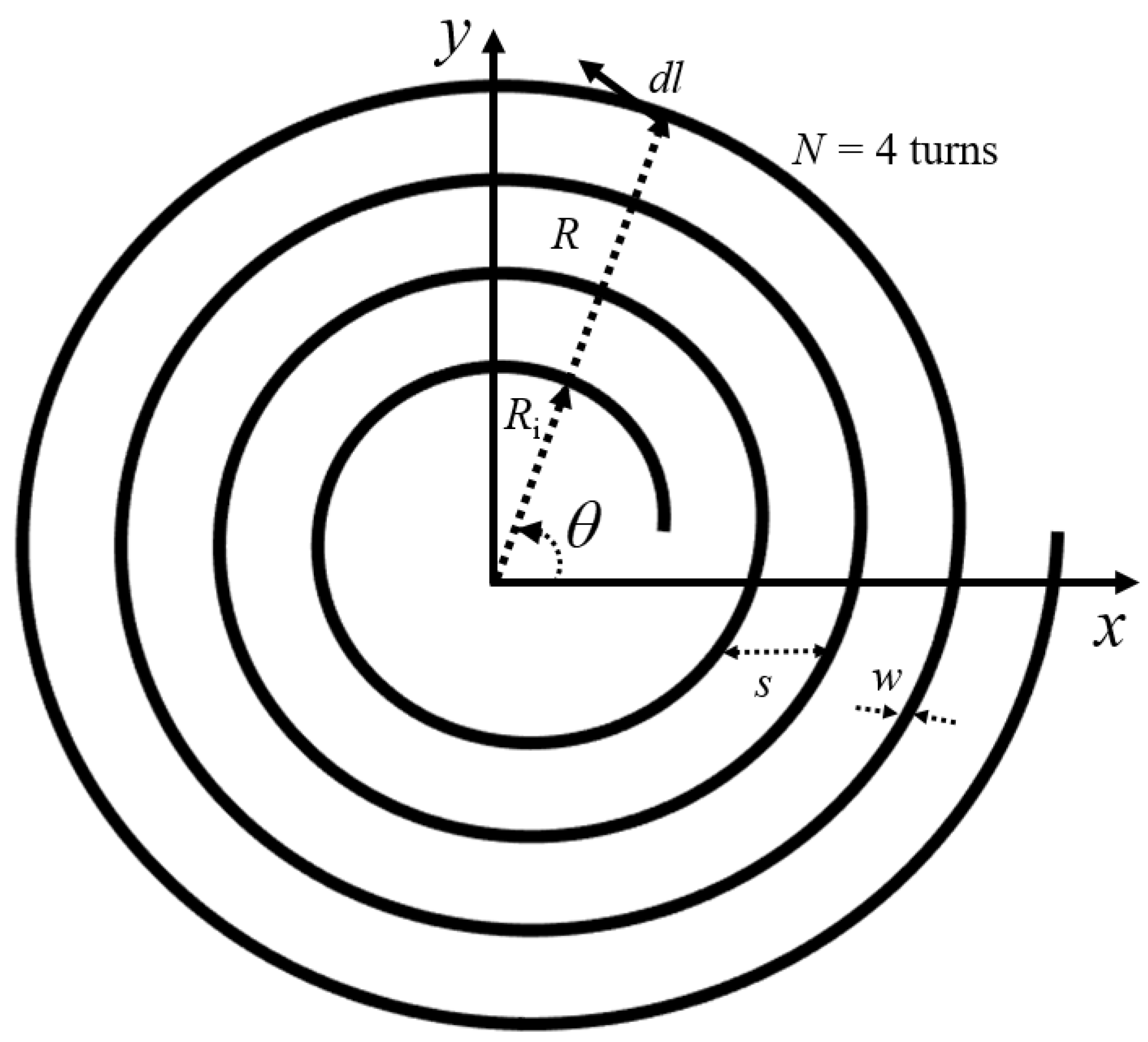
The self-inductance of circular planar spiral coil can be calculated by solving the Neumann’s integral formula for mutual inductance between two coils [10]. The geometrical parameters of the planar spiral, which lie on the x–y plane, is shown in Figure 1. It is assumed that the spiral coil carries constant current.
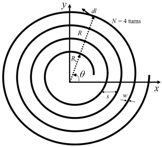
Figure 1.
Planar Spiral Coil.
In Figure 1, R is the outer radius of the spiral coil. θ is the angle of revolutions of R relative to x-axis. w shows the wire dimeter, and s is the distance between the turn.
The outer radius R is determined by using equation of planar spiral coil.
where Ri is the inner radius of the coil, and a is the pitch factor, which affects the distance between each turn.
N is the number of turns of the spiral coil.
When the radius of curvature of the spiral coil with uniform cross sectional area is larger than the radius of the conductor of the coil, the self-inductance of a planar spiral coil will be the mutual inductance between the original spiral coil and its fictitious coil placed at the distance of geometrical mean distance (GMD) of the conductor [11]. The geometrical mean distance for a Litz wire of round cross section is given in Equation (4)
g represents the geometrical mean distance, and r is the radius of the conductor.
The radius of the curvature (outer radius) of the original R1 and its fictitious spiral coil R2 are shown in Equations (5) and (6).
θ1 and θ2 are the angle of revolution of the original and its fictitious spiral coil, respectively.
The Neumann’s integral formula can be represented by the Equation (7).
where μ0 is the vacuum permeability, dl1 and dl2 are line components, and R is the distance between dl1 and dl2. The inductance of the planar coil can be computed by evaluating the parameters in Equation (7).
The dot product between dl1 and dl2 is given in Equation (10).
The distance R can be represented by using cosine formula.
Putting Equations (10) and (11) into Equation (7), the accurate equation of self-inductance of planar spiral coil is obtained as shown in Equation (12)
Equation (11) contains all the parameters that affect the inductance, such as inner and outer radius of the spiral coil, turn number, wire diameter, and the distance between the turns. The effect of each parameter on the inductance is discussed in detail in the following sections.
3. Comparison with Simulation and Conventional Methods
To verify the proposed method, inductances of several spiral coils with different geometrical parameters are calculated by using Equation (12). The inductances are also calculated by using the conventional method and by finite element method (FEM). Relative to simulation result, the error of calculation and the conventional results are computed. The error is calculated by , where RFem represents the simulation result, and Rc shows the calculated or conventional result.
The FEM simulation is conducted using ANSYS Maxwell 15 software. The type of solution is Magneto static. Mesh is assigned as a length based on the coil and its boundary. The element length is the default value. The current is assigned uniformly across the coil’s cross-section for simplicity’s purpose. Many conventional methods exist for the calculation of spiral coil [8,9,12]. Most of these methods adopted the modified Wheeler formula to compute the self-inductance of the spiral coil. Few of these formulas have been chosen for comparison in this work and are discussed below.
In [8], the self-inductance of the spiral coil is approximated by using the concept of average of diameter of the coil as shown in Equation (13).
The self-inductance of the spiral coil is determined based on the equivalent current densities and approximation of the spiral [9]. This approximation method equation of the inductance of the spiral coil is given in Equation (16).
Ci is the dependent coefficient. For the spiral coil of circular shape, the value of C1 is 1, C2 is 2.46, C3 is 0.00, and C4 is 0.20.
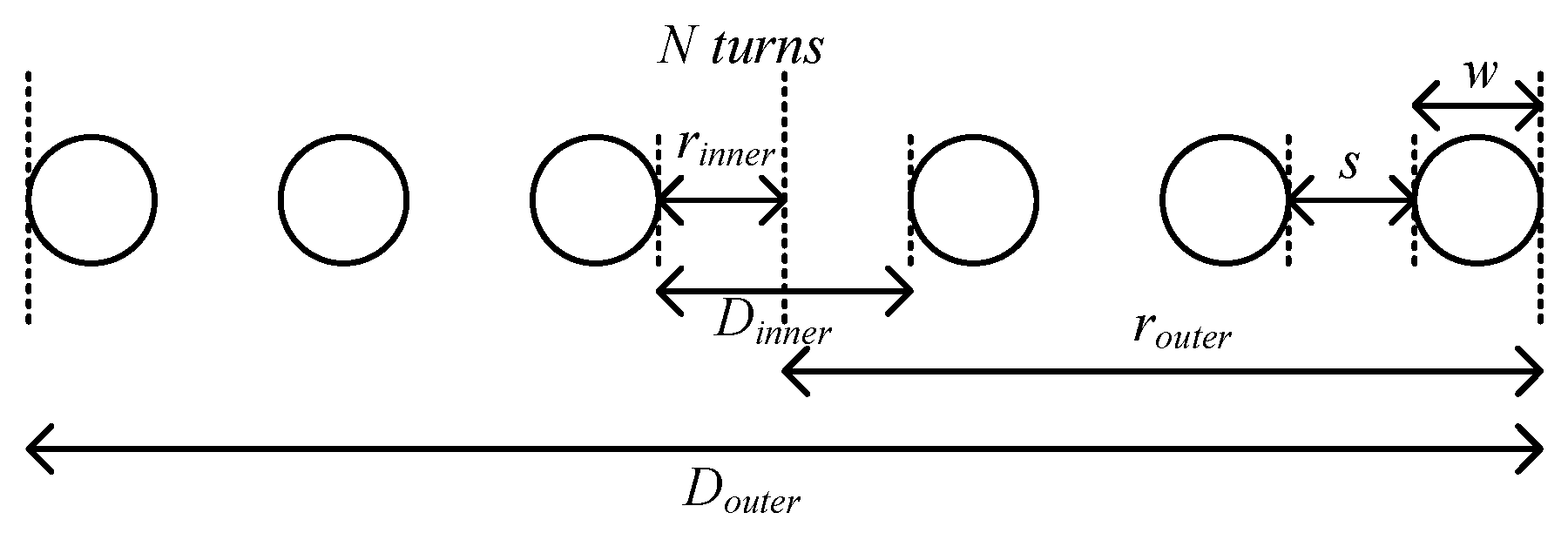
Using the Wheeler approximation method, the self-inductance of the spiral coil is computed [12]. This formula is invalid when gap distance between the turn is smaller than the diameter of the wire and when the coil has a fewer number of turns. This approximation formula is denoted in Equation (17) mathematically and is represented graphically in Figure 2.
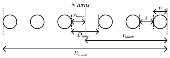
Figure 2.
Cross-sectional view of spiral coil.
To compute the inductance of a single-layer of circular spiral coil, a modified Harold A. Wheeler formula is used in Equation (18).
where N is the total number of turns, w is the wire diameter, s is the gap between the turn, and din and dout are the inner and outer diameter of the wire, respectively.
The Equations (13), (16)–(18) are derived by using the Wheeler formula or its modified form to calculate the inductance of a spiral coil. Therefore, the self-inductance of the planar spiral coil will be similar using any of these formulas, and thus, their error relative to the proposed method will also be the same. Any of these formulas can be chosen for comparison with the proposed method.
The comparison of inductance by variation of each geometrical parameter is discussed in the following subsection.
3.1. Variation of the Outer Radius
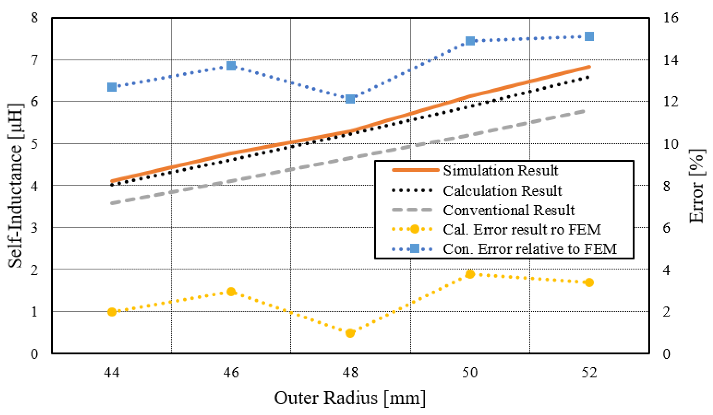
For the different outer radius, the behavior of the self-inductance of a spiral is compared for a wire radius r = 1.8 mm, number of turn N = 10, and gap between the turn s = 4 mm. The comparison detail is shown in Figure 3. The above figure indicates that the inductance of the coil increases when the outer radius or outer diameter of the coil increases. It can be explained by the definition of the inductance of a coil.
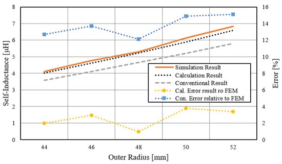
Figure 3.
The behavior of the self-inductance of the spiral coil as a function of outer radius.
One of the factors the inductance depends on is the size of the coil. As the size of the coil increases, the inductance also increases. The inductance obtained from the conventional method is lower than the calculation and simulation result. Therefore, relative to the simulation result, the error of the conventional method is higher, which is around 16% compared to the error of the calculation result, which is below 4%. Thus, the proposed method offers good accuracy in terms of the outer radius variations.
3.2. Variation of the Wire Diameter
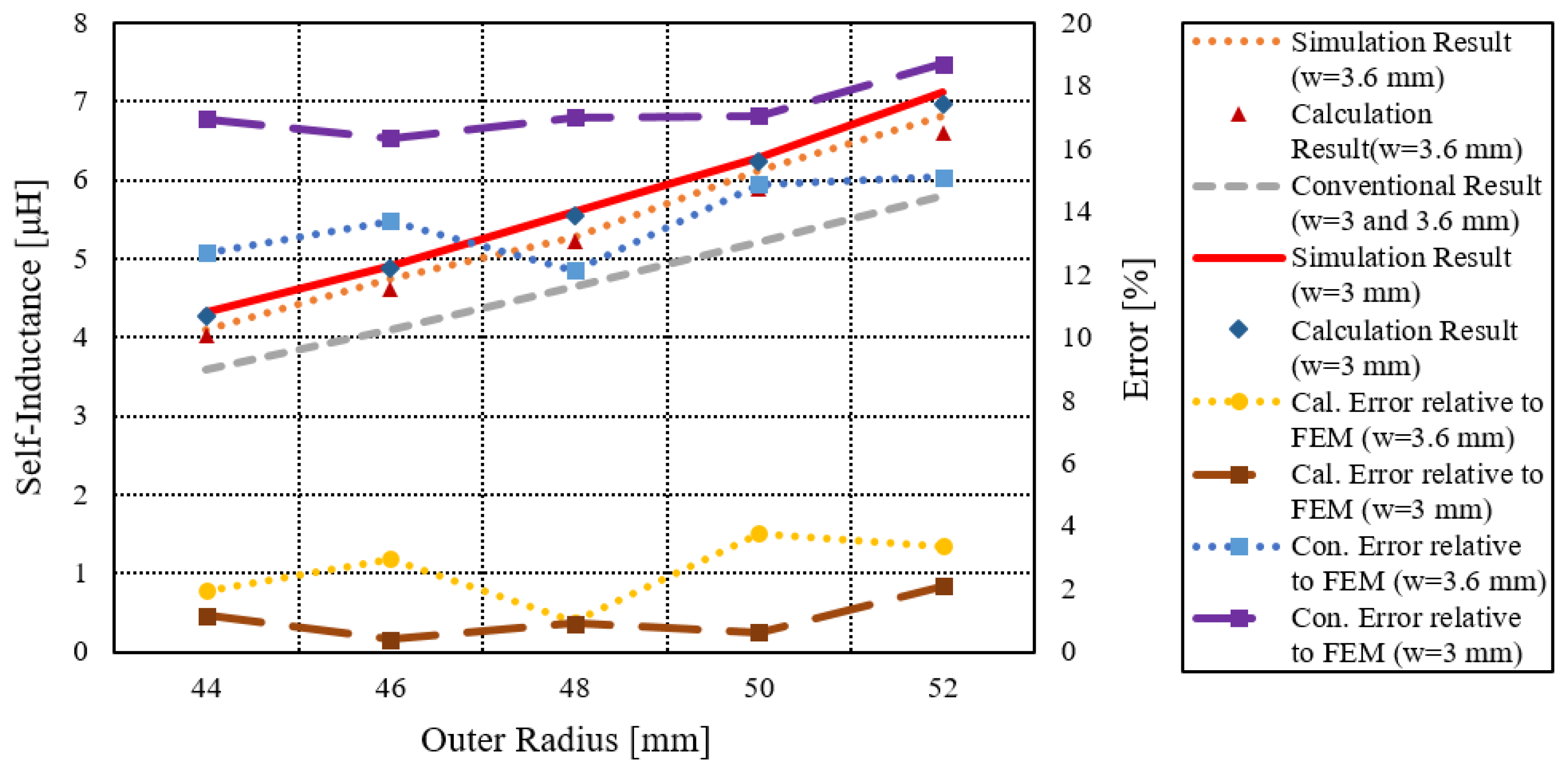
Figure 4 shows the behavior of inductance for the wire diameters 3 mm and 3.6 mm. The values of other parameters are the same as shown in Section 3.1. Compared to large-diameter wire, the inductance of the smaller wire diameter of the coil is higher in the calculation and simulation result. However, the inductance is constant when the diameter of a wire is modified in many conventional formulas because these formulas have not considered the wire diameter. Using the conventional method to compute the inductance, the error is below 17% for wire diameter of 3.6 mm and 20% for w = 3.0 mm when compared with the simulation result, and the error increases as the wire diameter decreases. However, the error of the calculation result is less than 4% for all cases, which verifies its accuracy.
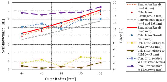
Figure 4.
The effect of the variation of diameter of the wire on the self-inductance of the spiral coil.
3.3. Variation of the Number of Turns
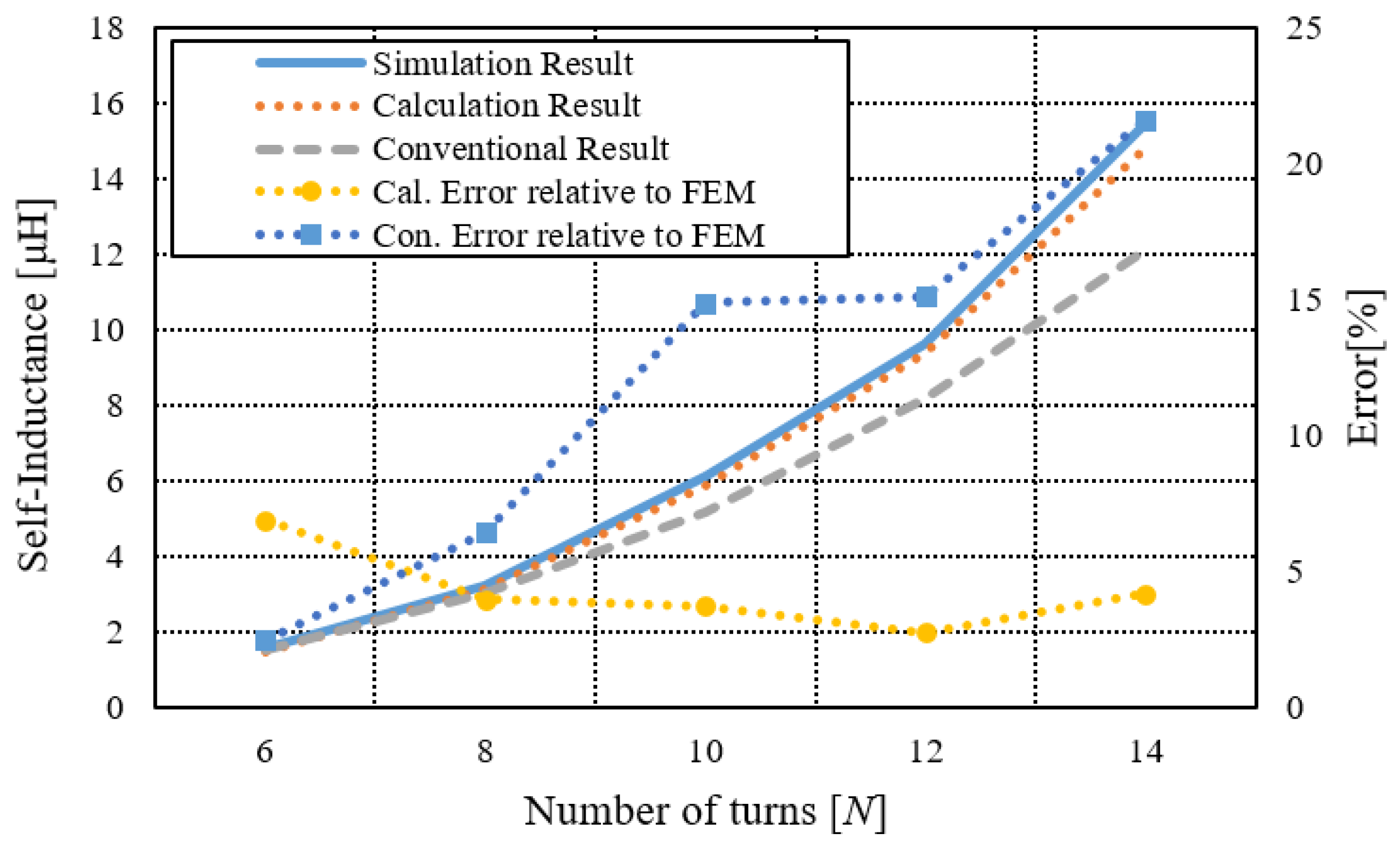
Figure 5 shows the comparison self-inductance calculation and conventional results at a different number of turns for Ri = 10 mm, s = 4 mm, and w = 3.6 mm. When the number of turns on a coil is increased, inductance rises. In the conventional methods, the error increases with the increase in the number of turns; however, it showed better accuracy for fewer number of turns compared to the calculation result. It can be concluded that the conventional formula is suitable for applications where coils with fewer number of turns are required. On the other hand, the error of the calculation result relative to the FEM result is less than 6%, and accuracy is maintained for all cases.
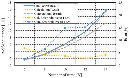
Figure 5.
The effect of the change of the number of turns on the inductance of the spiral coil.
3.4. Variation of the Gap between the Turns
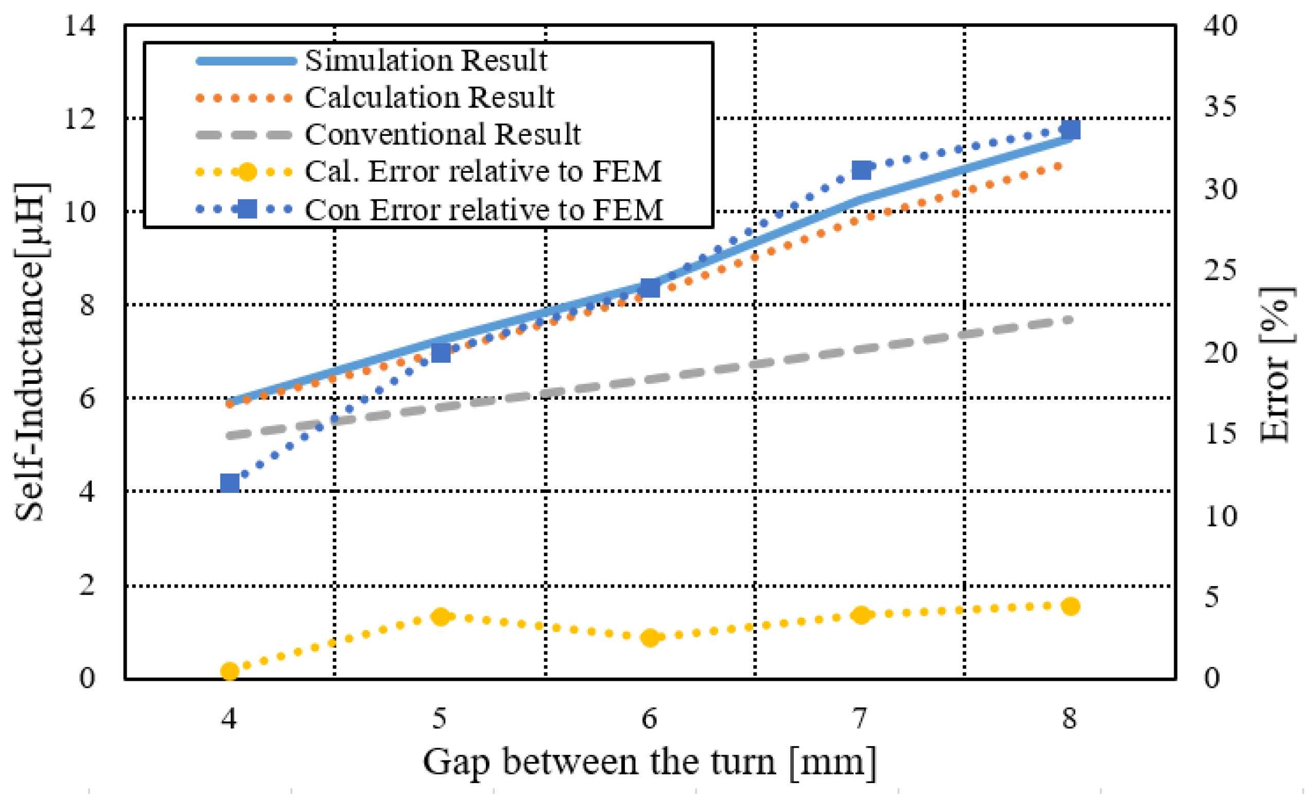
Figure 6 shows the behavior of the inductance of the spiral coil at the different gaps between the turns with w = 3.6 mm, Ri = 10 mm, and N = 10. The geometry of the coil is expended with the increase in the gap between the turns, thus increasing the inductance. The error rises sharply as the gap between the turns’ increases by using the conventional method. However, the calculation result has an error of below 5% for the increase in the gap between the turns. Thus, these comparisons confirm the validity of the calculation result for different variations in the geometrical parameter of the spiral coil.
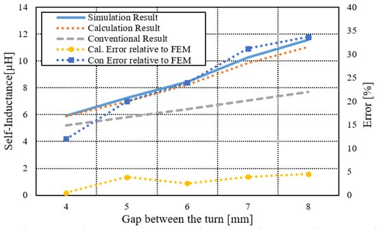
Figure 6.
The influence of the change of the gap between a turn on the inductance of the spiral coil.
4. Experimental Verification
To validate the proposed method experimentally, the calculation of some parameters is necessary for fabricating the spiral coil, such as the length of the wire and DC resistances. Moreover, the type of the wire, soldering quality, and the bobbin for holding the wire also have to be considered. Each of these factors is discussed briefly in the following subsection.
4.1. Selection of the Wire
Various types of wires are used for making a coil, but Litz wire is chosen in this study due to its vast advantages and multiple usages in many applications, such as crystal radio, loop antenna, high Q coils, switching power supply, and induction heating equipment. Litz wire is made by putting multiple strands of thin, insulated wire together side by side. The insulated strands each carry a portion of the current, reducing the skin and proximity impact. Due to these effects, Litz wire reduces the increase in resistance at higher frequencies [13]. This wire can be used up to about 1 MHz. In this work, 500 strands of Litz wire, each strand with 0.1-mm diameter, are used to make the spiral coils. The diameter of wire is around 3.6 mm, which is decided empirically by Equation (19).
where De is an estimated diameter of the Litz wire, Ds is the diameter of one strand wire, and Ns is total number of strands.
4.2. Soldering Quality
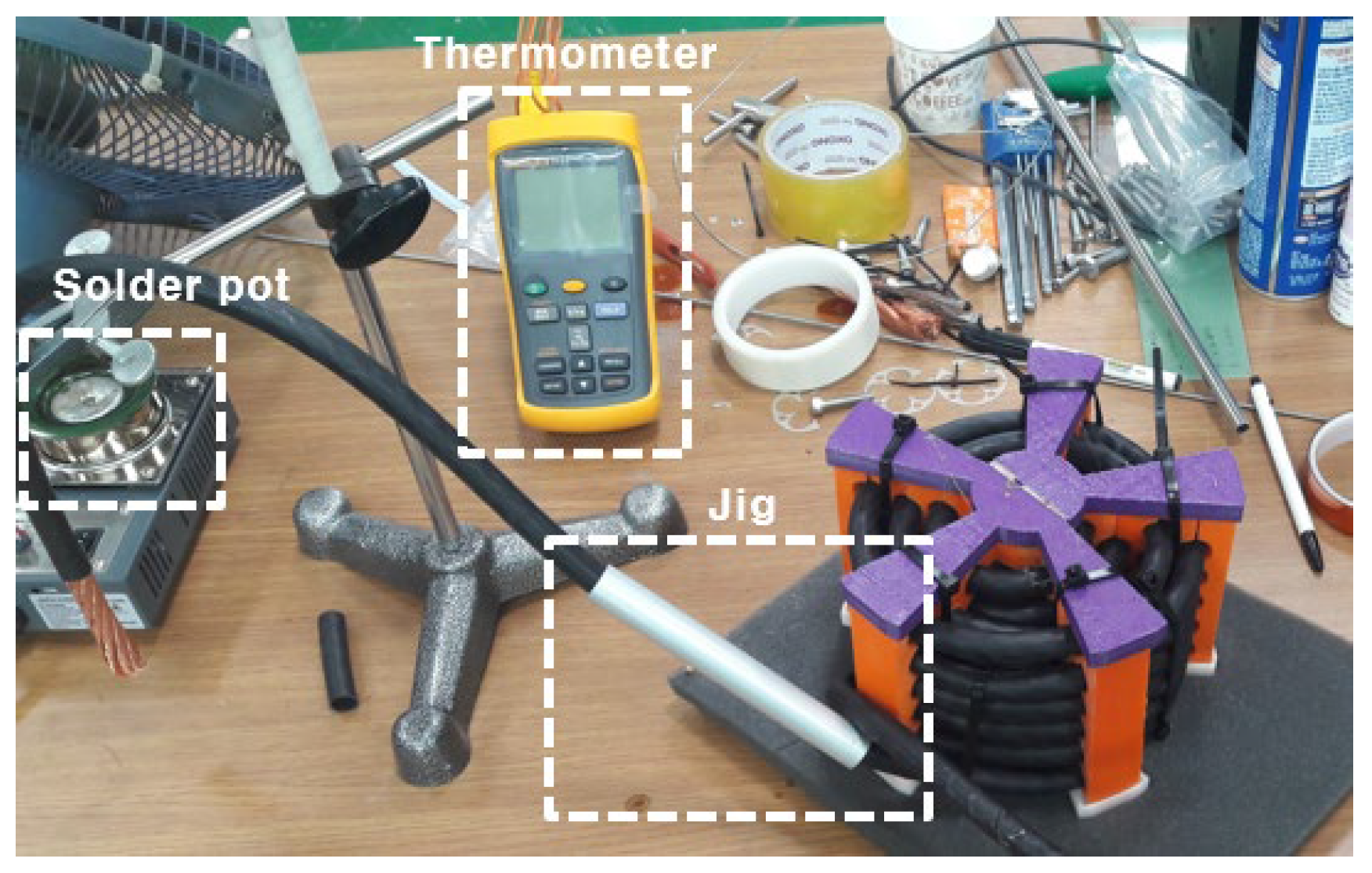
The wire diameter, which is one of the factors affecting the inductance, can be reduced during soldering. Therefore, proper process and precaution are needed for good-quality soldering. The temperature of the soldering material (lead) has to be distributed equally inside the soldering pot, and it is better to choose the soldering material with fewer impurities. The soldering temperature changes with the type and the width of the wire. Thus, the temperature should be regulated and checked with a thermometer. Finally, a special jig and proper soldering set are required as shown in Figure 7.
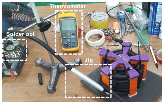
Figure 7.
Soldering setup.
4.3. Calculation of Wire Length and Wire Resistance
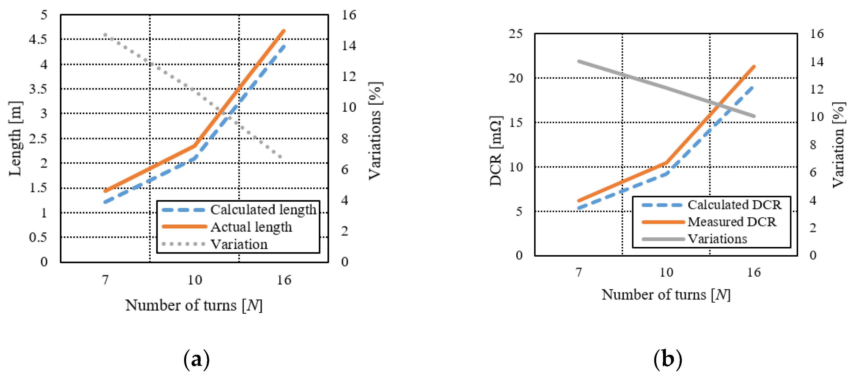
The length of the wire is proportional to its DC resistance. Therefore, it is important to compute the length of the wire and the resistance. The total length and the resistance of the wire can be calculated by Equations (20) and (21). Furthermore, the calculated and the actual length and DC resistance of the wire are shown in Figure 8a,b. The DC resistance is measured using Gwinstek LCR-6020.
where l the length of wire; σ is constant, and its value is 58,000; n is the number of strands; and r is the radius of one strand.
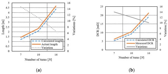
Figure 8.
Comparison of calculated and measured length and DCR. (a) Length comparison. (b) DCR comparison.
4.4. Bobbin
To hold the wire of the spiral coil, various bobbins with different wire diameters, number of turns, the distance between the turn, and outer radius are fabricated using a 3-D printer. The printing filament was PLA (polylactic acid). Figure 9a,b shows the bobbin and the spiral coil with the bobbin.
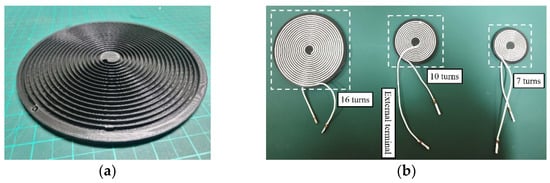
Figure 9.
Spiral coil and bobbin. (a) Bobbin. (b) Spiral coil wound on the bobbins.
4.5. Experimental Result
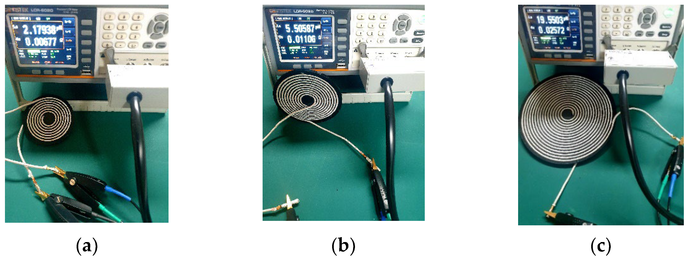
To validate the proposed method, three random sampled coils with different sizes are fabricated, and their inductances are measured using Gwinstek LCR-6020 m. The testing frequency for this measurement is 20 kHz. Finally, the measurement results are compared with the calculation result, and their results are presented in Table 1. In addition, the measured results are also shown in Figure 10.

Table 1.
Comparison of the calculation and measurement result.
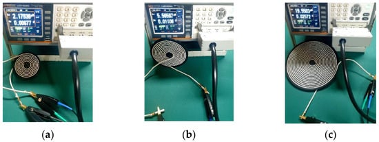
Figure 10.
Measured inductances of the spiral coil with different sizes. (a) 7 turns. (b) 10 turns. (c) 16 turns.
It can be seen from Table 1 that the calculation results are in good agreement with the measurement result. The relative error is less than 5%.
5. Conclusions
This paper introduces a new way to compute the inductance of the single-layer planar spiral. Utilizing the geometric mean distance principle, the proposed method is determined by solving Neumann’s formula for the mutual inductance between the two coils. Inductances of various size of spiral coils with different outer radiuses, number of turns, wire diameter, and turn gap are calculated numerically. The calculated results are verified by simulation, experimental, and conventional formulas. The error of the calculation results is less than 5% for all cases compared to the conventional formula, which was more than 20%. Moreover, the proposed method contains all the parameters influencing the inductance. However, the conventional formulas have not included all the parameters, leading to faulty results.
In this study, the inductance of the single-layer spiral coil is computed for uniform current flow in the wire. However, the inductance can be different for non-uniform currents. In this case, it requires further research, and it can be considered in future work.
Author Contributions
I.H. proposed the theoretical model and conducted the experiment; D.-K.W. revised the draft and provided guidance. All authors have read and agreed to the published version of the manuscript.
Funding
This research received no external funding.
Conflicts of Interest
The authors declare no conflict of interest.
References
- Liu, Y.; Terry, T.Y. Coupled Planar Coil (CPC) Antenna as a Displacement Sensor for NFC or HF RFID Tags. In Proceedings of the 2020 IEEE International Conference on RFID (RFID), Orlando, FL, USA, 5–9 October 2020; IEEE: Manhattan, NY, USA, 2020; pp. 1–6. [Google Scholar]
- Iftikhar, H.; Woo, D.-K. Simplified Mutual Inductance Calculation of Planar Spiral Coil for Wireless Power Applications. Sensors 2022, 22, 1537. [Google Scholar] [CrossRef] [PubMed]
- Shahid, H.; Mohamed, A.; Ahmed, K.-B.L.; Kim, Y.C. Fuzzy logic weight based charging scheme for optimal distribution of charging power among electric vehicles in a parking lot. Energies 2020, 13, 3119. [Google Scholar] [CrossRef]
- Young, D.J. Wireless powering and data telemetry for biomedical implants. In Proceedings of the 2009 Annual International Conference of the IEEE Engineering in Medicine and Biology Society, Minneapolis, MN, USA, 3–6 September 2009; IEEE: Manhattan, NY, USA, 2009; pp. 3221–3224. [Google Scholar]
- Chan, H.L.; Cheng, K.W.E.; Sutanto, D. A simplified Neumann’s formula for calculation of inductance of spiral coil. In Proceedings of the 2000 Eighth International Conference on Power Electronics and Variable Speed Drives (IEE Conf. Publ. No.475), London, UK, 18–19 September 2000; pp. 69–73. [Google Scholar]
- Ram Rakhyani, A.K.; Shahriar, M.; Mu, C. Design and optimization of resonance-based efficient wireless power delivery systems for biomedical implants. IEEE Trans. Biomed. Circuits Syst. 2010, 5, 48–63. [Google Scholar] [CrossRef] [PubMed]
- Li, X.; Hanru, Z.; Fei, P.; Yang, L.; Tianyang, Y.; Bo, W.; Dongming, F. A wireless magnetic resonance energy transfer system for micro implantable medical sensors. Sensors 2012, 12, 10292–10308. [Google Scholar] [CrossRef] [PubMed]
- Jie, L.; Costinett, D. Analysis and design of a series self-resonant coil for wireless power transfer. In Proceedings of the 2018 IEEE Applied Power Electronics Conference and Exposition (APEC), San Antonio, TX, USA, 4–8 March 2018; pp. 1052–1059. [Google Scholar]
- Tao, L.; Wei, Z.; Chi, H.; Yin, B. Inductance calculation of multilayer circular printed spiral coils. J. Phys. Conf. Ser. 2019, 1176, 062045. [Google Scholar]
- Inan, U.S. Engineering Electromagnetics; Pearson Education: Noida, India, 1998. [Google Scholar]
- Kalantarov, P.L. Inductance Calculations; National Power Press: Moscow, Russia, 1955. [Google Scholar]
- Chatterjee, S.; Iyer, A.; Bharatiraja, C.; Vaghasia, I.; Valiveti, R. Design optimisation for an efficient wireless power transfer system for electric vehicles. Energy Procedia 2017, 117, 1015–1023. [Google Scholar] [CrossRef]
- Väisänen, V.; Hiltunen, J.; Nerg, J.; Silventoinen, P. AC resistance calculation methods and practical design considerations when using litz wire. In Proceedings of the IECON 2013—39th Annual Conference of the IEEE Industrial Electronics Society, Vienna, Austria, 10–13 November 2013; pp. 368–375. [Google Scholar]

Publisher’s Note: MDPI stays neutral with regard to jurisdictional claims in published maps and institutional affiliations. |
© 2022 by the authors. Licensee MDPI, Basel, Switzerland. This article is an open access article distributed under the terms and conditions of the Creative Commons Attribution (CC BY) license (https://creativecommons.org/licenses/by/4.0/).