
Dual-Polarized Dipole Antenna for Wireless Data and Microwave Power Transfer

Abstract
:1. Introduction
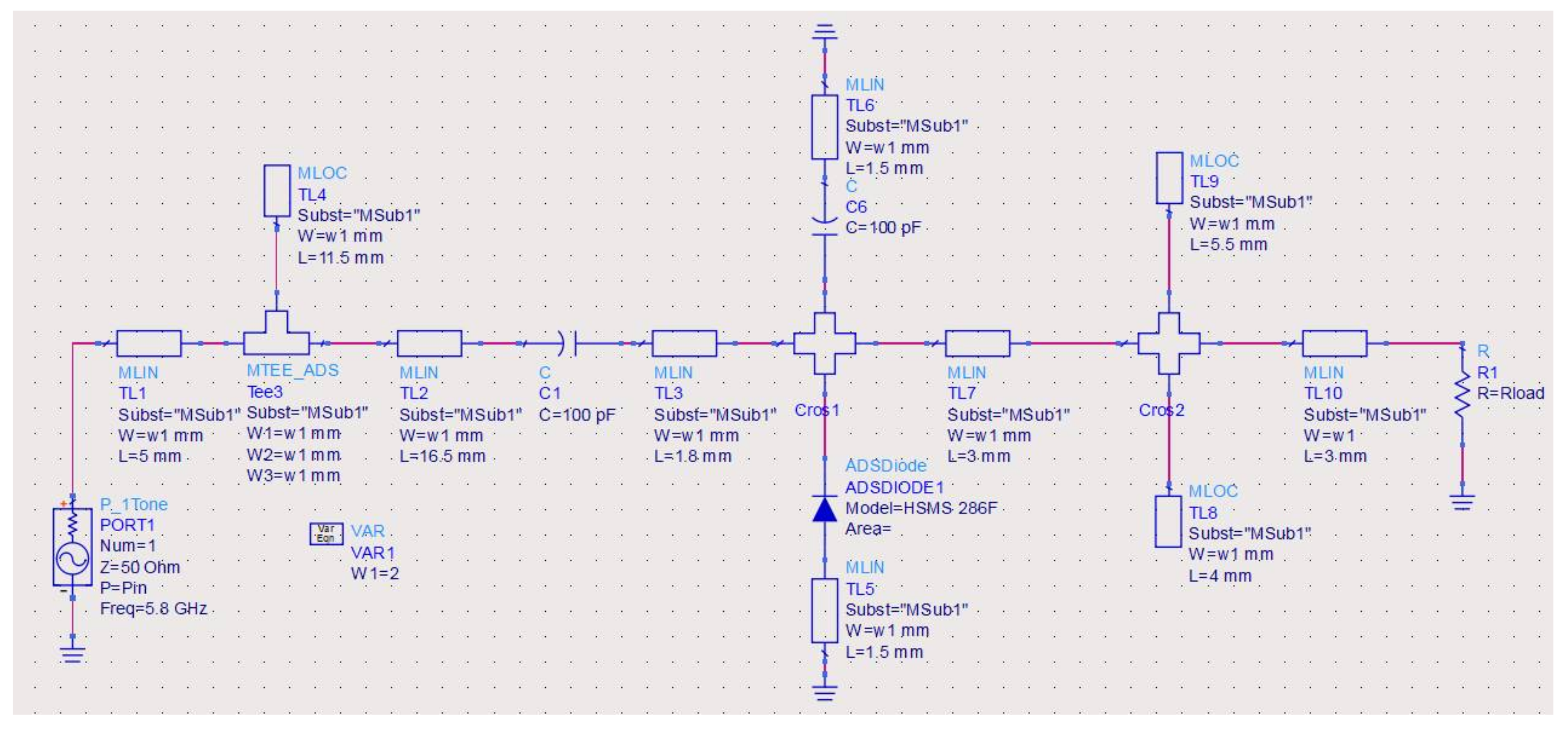
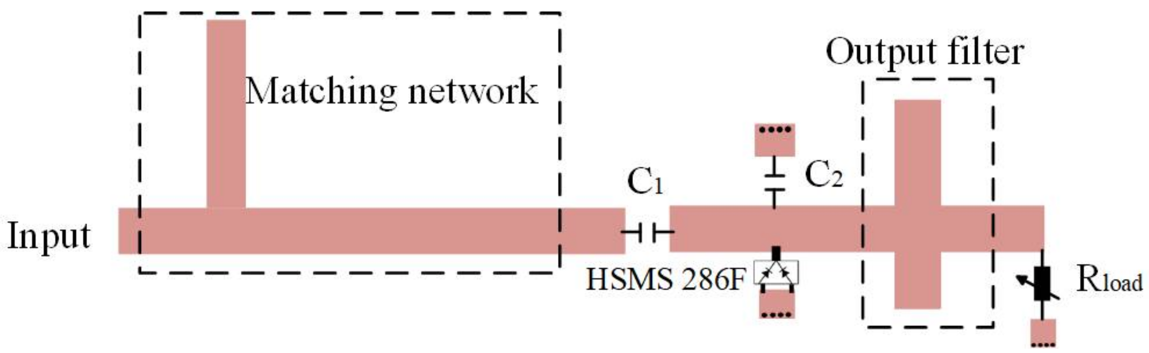
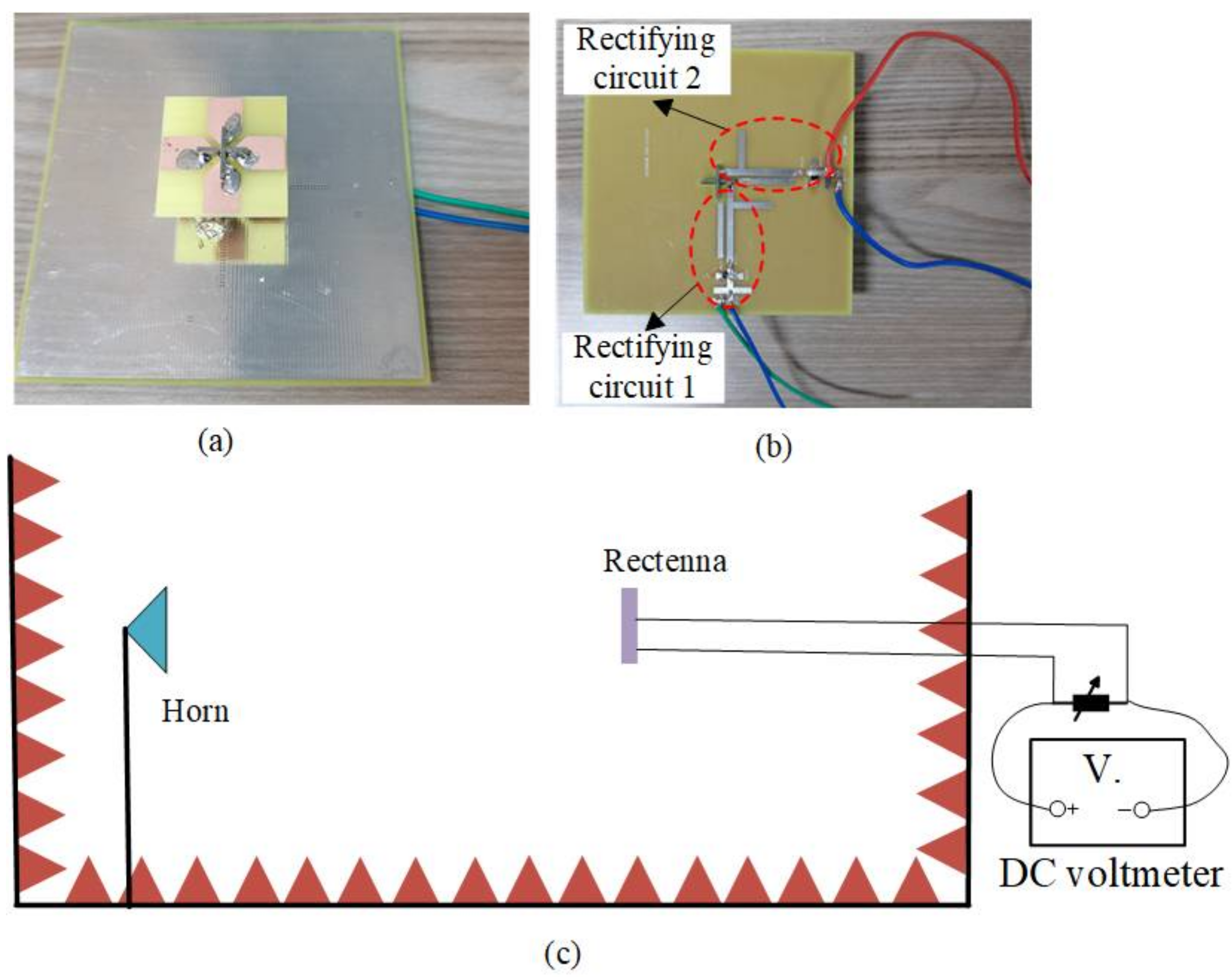
2. Rectenna Design
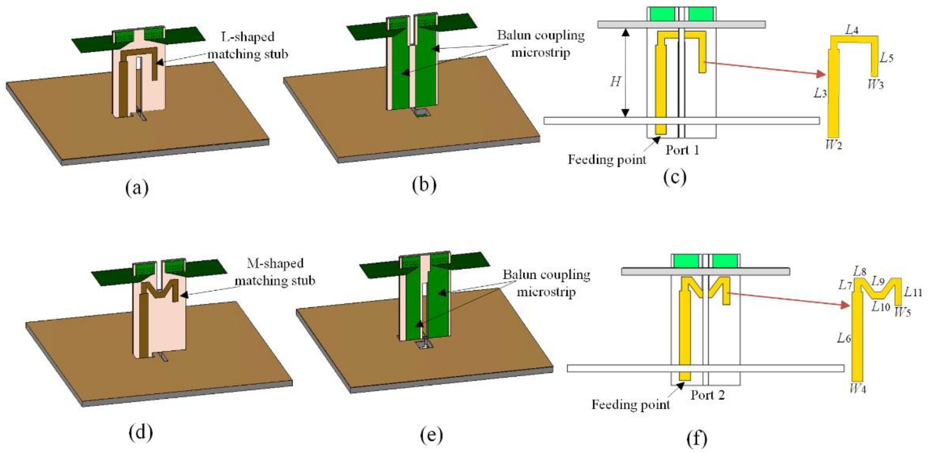
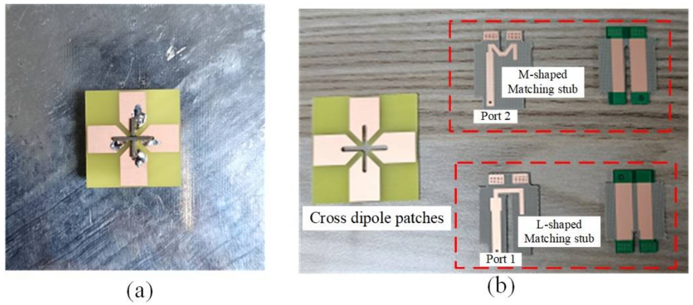
Antenna Structure
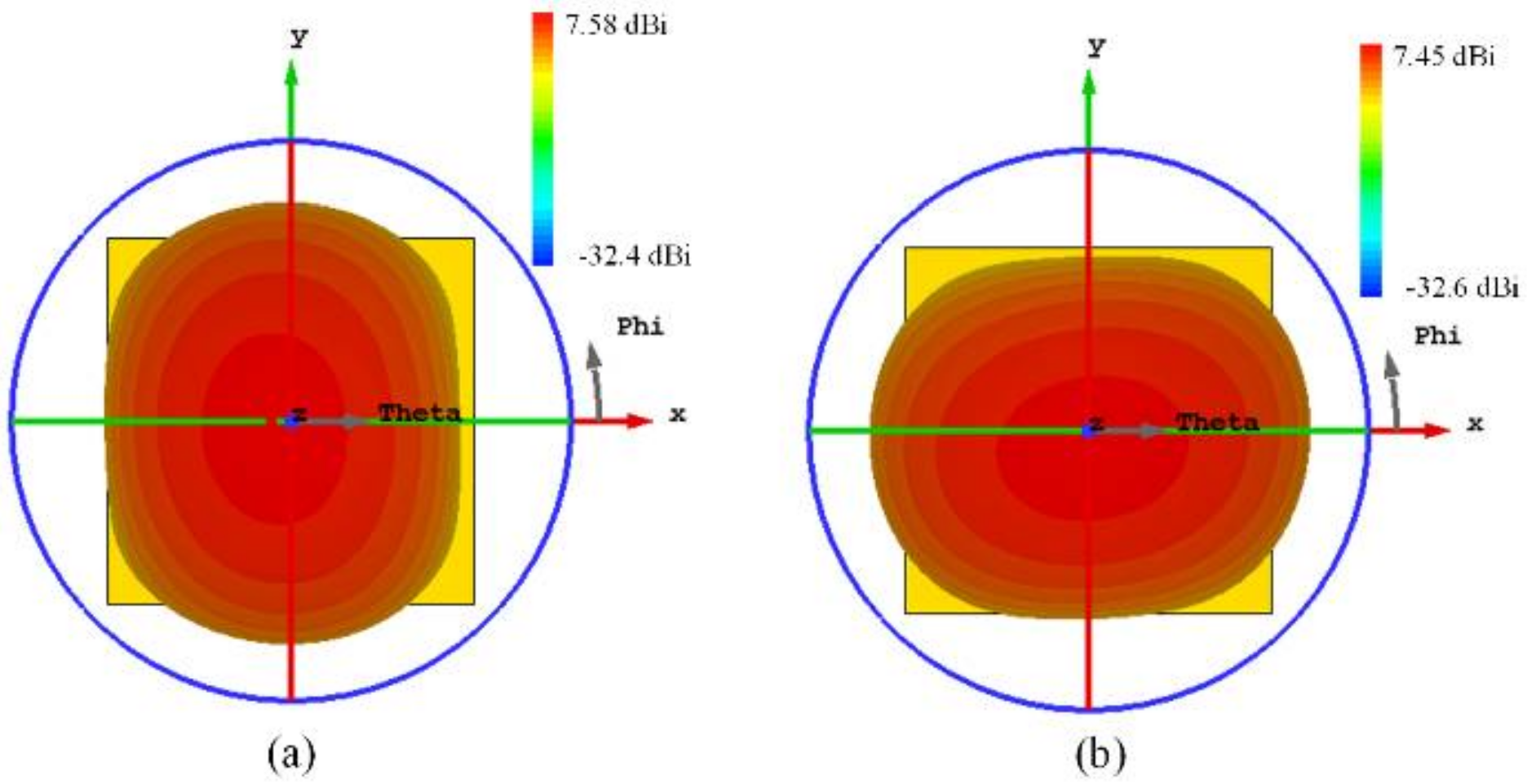
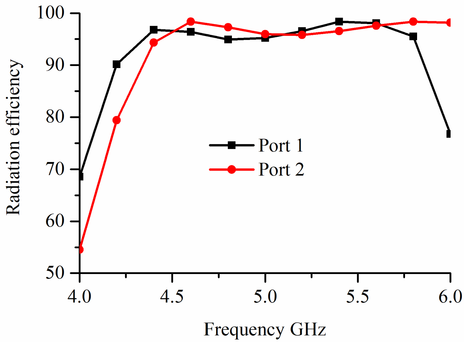
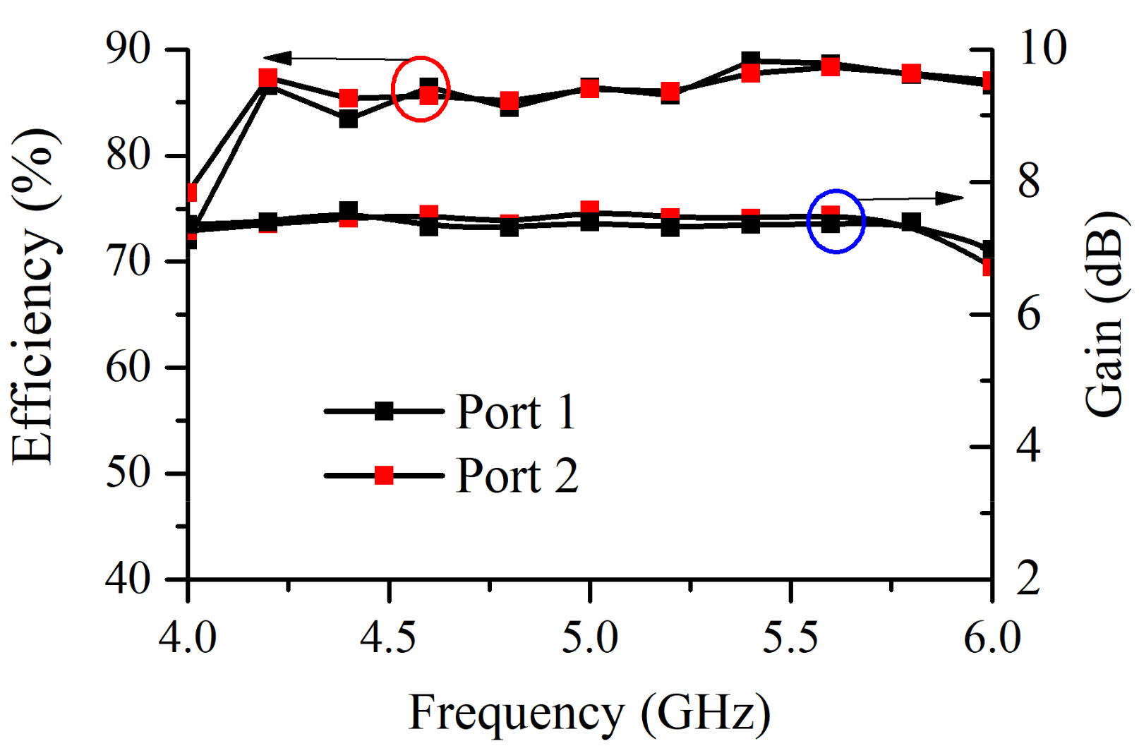
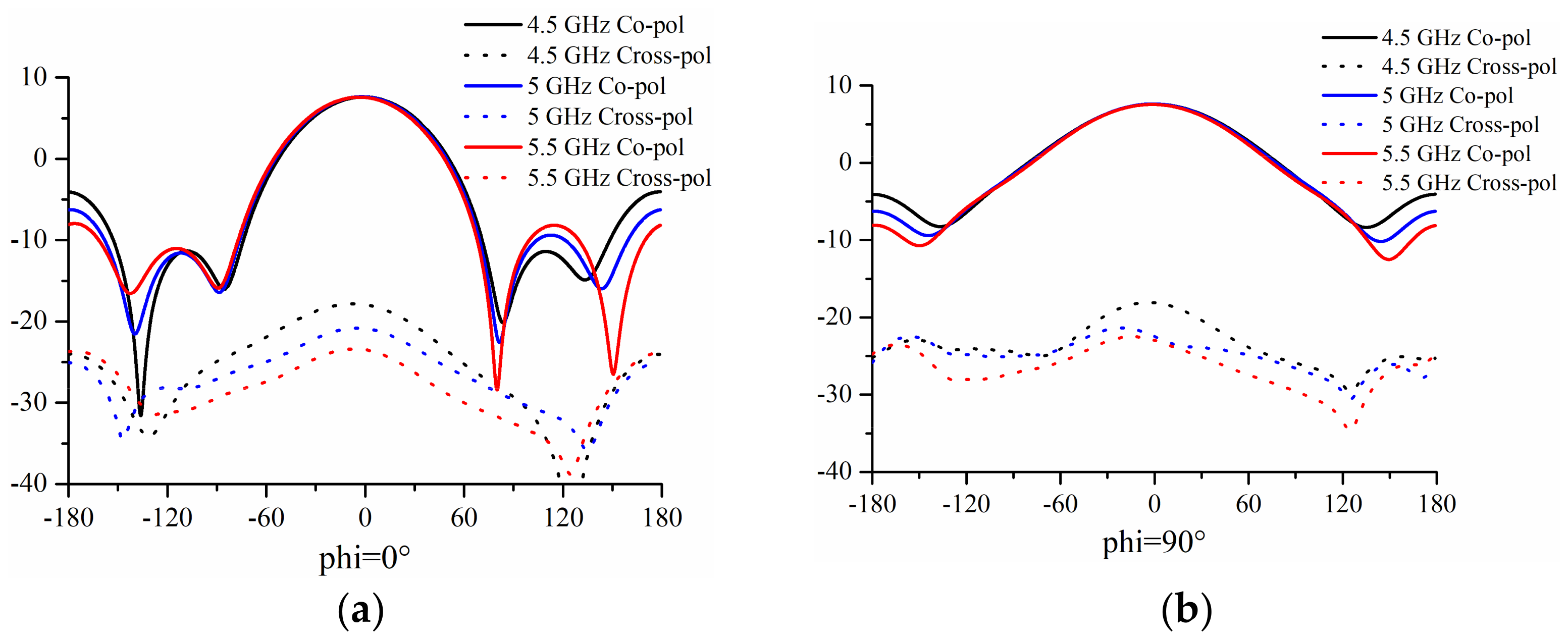
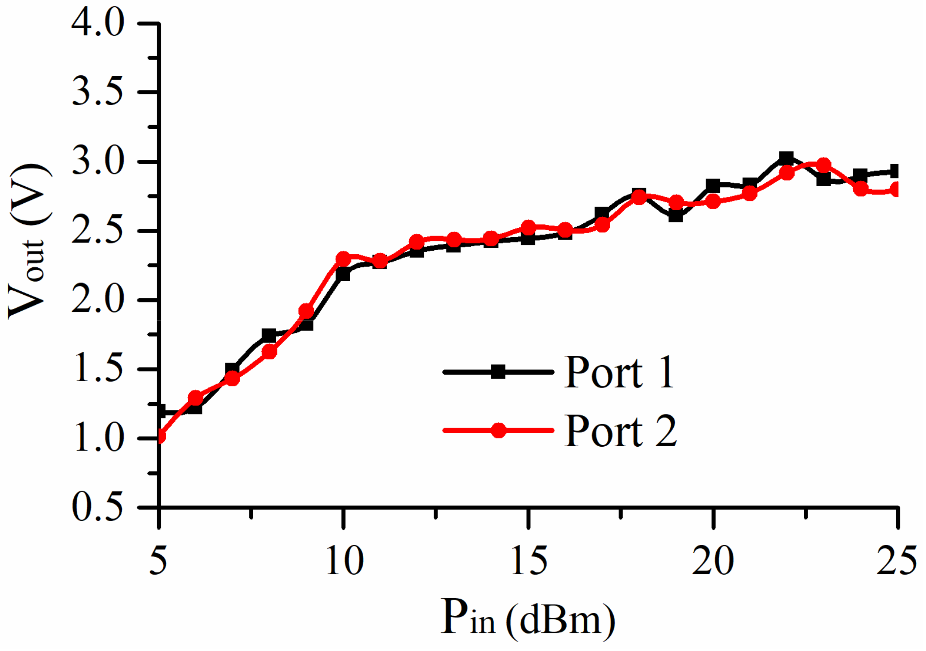
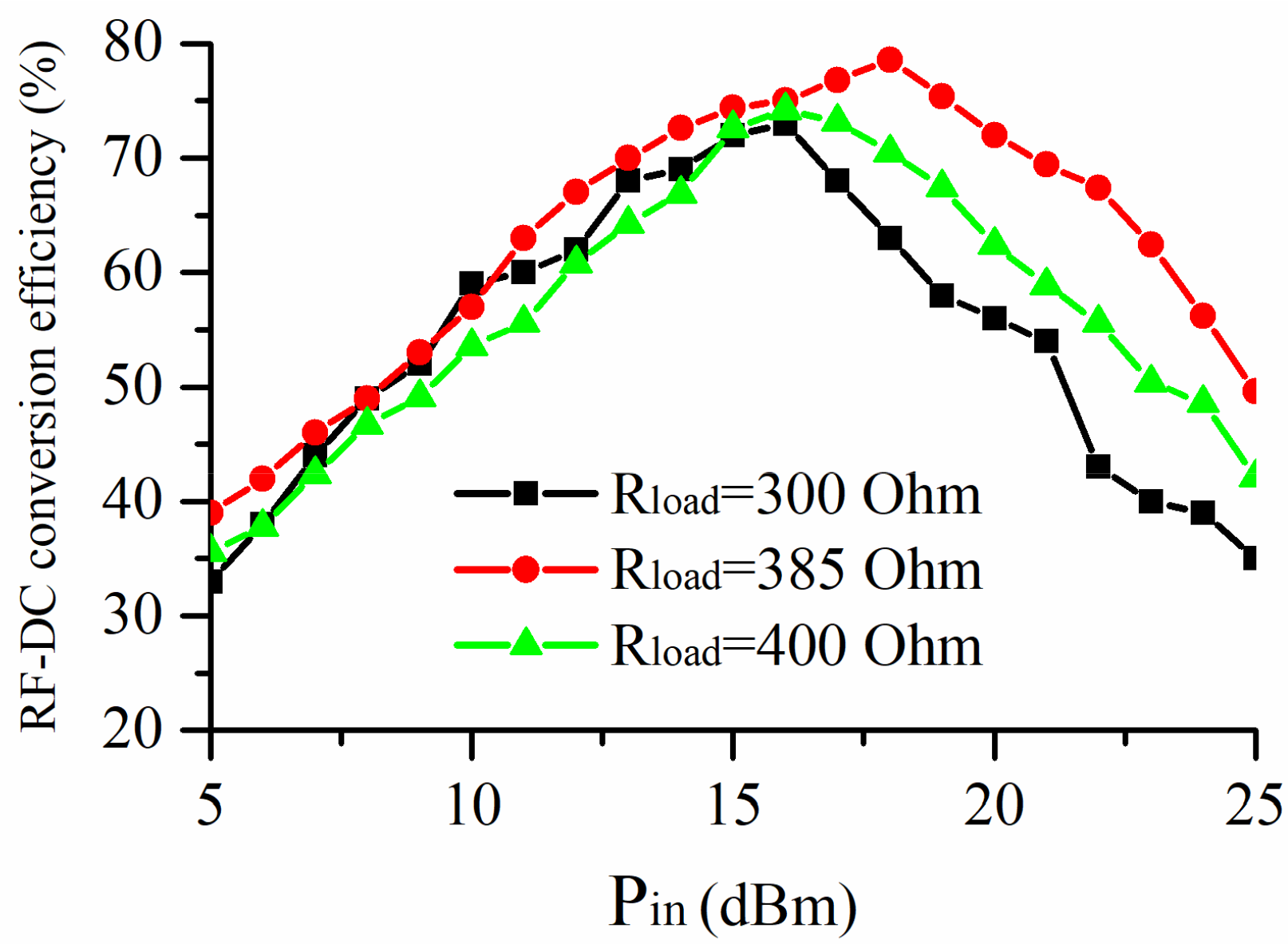
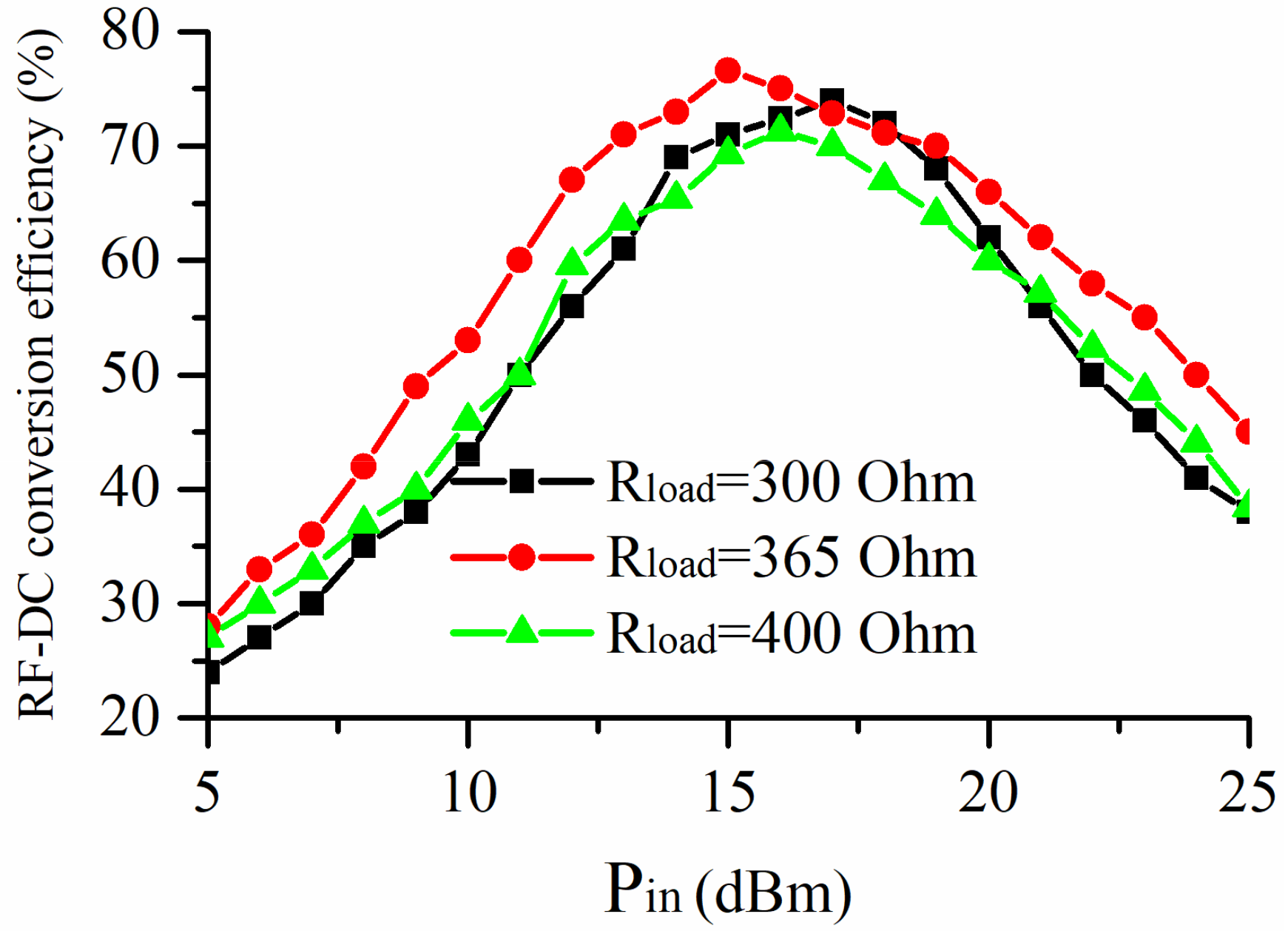
3. Rectenna Measured Results
4. Conclusions
Author Contributions
Funding
Institutional Review Board Statement
Informed Consent Statement
Data Availability Statement
Conflicts of Interest
References
- Li, X.; Yang, L.; Huang, L. Novel design of 2.45-GHz rectenna element and array for wireless power transmission. IEEE Access 2019, 7, 28356–28362. [Google Scholar] [CrossRef]
- Zhu, G.-L.; Du, J.-X.; Yang, X.-X.; Zhou, Y.-G.; Gao, S. Dual-Polarized communication rectenna array for simultaneous wireless information and power transmission. IEEE Access 2019, 7, 141978–141986. [Google Scholar] [CrossRef]
- Wagih, M.; Hilton, G.S.; Weddell, A.S.; Beeby, S. Weddell and Steve Beeby. Dual-polarized wearable antenna/rectenna for full-duplex and mimo simultaneous wireless information and power transfer (SWIPT). IEEE Open J. Antennas Propag. 2021, 2, 844–857. [Google Scholar] [CrossRef]
- Ding, S.; Koulouridis, S.; Pichon, L. Implantable wireless transmission rectenna system for biomedical wireless applications. IEEE Access 2020, 8, 195551–195558. [Google Scholar] [CrossRef]
- Asif, S.M.; Iftikhar, A.; Hansen, J.W.; Khan, M.S.; Ewert, D.L.; Braaten, B.D. A novel RF-power wireless pacing via a rectenna based pacemaker and a wearable transmit-antenna array. IEEE Access 2019, 7, 1139–1148. [Google Scholar] [CrossRef]
- Zhang, H.; Ngo, T. Linear-polarization-insensitive rectenna design for ground-to-air microwave power transmission. IEEE Access 2020, 8, 101702–101707. [Google Scholar] [CrossRef]
- Tomura, T.; Hirokawa, J.; Furukawa, M.; Fujiwara, T.; Shinohara, N. Eight-port feed radial line slot antenna for wireless power transmission. IEEE Open J. Antennas Propag. 2021, 2, 170–180. [Google Scholar] [CrossRef]
- Lu, P.; Song, C.; Cheng, F.; Zhang, B.; Huang, K. A self-biased adaptive reconfigurable rectenna for microwave power transmission. IEEE Trans. Antennas Propag. 2020, 35, 7749–7754. [Google Scholar] [CrossRef]
- Lu, P.; Yang, X.-S. Pattern reconfigurable rectenna with omni-directional/directional radiation modes for MPT with multiple transmitting antennas. IEEE Microw. Wirel. Compon. Lett. 2019, 29, 826–829. [Google Scholar] [CrossRef]
- Lu, P.; Yang, X.-S.; Li, J.-L.; Wang, B.-Z. Polarization reconfigurable broadband rectenna with tunable matching network for microwave power transmission. IEEE Trans. Antennas Propag. 2016, 63, 1136–1141. [Google Scholar] [CrossRef]
- Lu, P.; Song, C.; Huang, K.M. A two-port multipolarization rectenna with orthogonal hybrid coupler for simultaneous wireless information and power transfer (SWIPT). In IEEE Transactions on Antennas and Propagation; IEEE: Piscataway, NJ, USA, 2020. [Google Scholar]
- Lou, X.; Yang, G. A dual linearly polarized rectenna using defected ground structure for wireless power transmission. IEEE Microw. Wirel. Compon. Lett. 2018, 28, 828–830. [Google Scholar] [CrossRef]
- Tu, W.; Hsu, S.-H.; Chang, K. Compact 5.8 GHz rectenna using steeped-impedance dipole antenna. IEEE Antennas Wirel. Propag. Lett. 2007, 6, 282–284. [Google Scholar] [CrossRef]
- Niotaki, K.; Kim, S.; Jeong, S.; Collado, A.; Georgiadis, A.; Tentzeris, M.M. A compact dual-band rectenna using slot-loaded dual band folded dipole antenna. IEEE Antennas Wirel. Propag. Lett. 2013, 12, 1634–1637. [Google Scholar] [CrossRef]
- Song, C.; Huang, Y.; Zhou, J.; Zhang, J.; Yuan, S.; Carter, P. A high-efficiency broadband rectenna for ambient wireless energy harvesting. IEEE Trans. Antennas Propag. 2015, 63, 3486–34955. [Google Scholar] [CrossRef] [Green Version]
- Ou, J.-H.; Pan, J.; Dong, S.-W.; Zhang, X.Y. A dual-polarized rectenna with high efficiency at low input power density. In Proceedings of the 2020 14th European Conference on Antennas and Propagation (EuCAP), Copenhagen, Denmark, 15–20 March 2020. [Google Scholar]
- Lin, W.; Ziolkowski, R. Electrically small Huygens antenna-based fully-integrated wireless power transfer and communication system. IEEE Access 2019, 7, 39762–39769. [Google Scholar] [CrossRef]
- Zhang, Y.-M.; Li, J.-L. A dual-polarized antenna array with enhanced interport isolation for far-field wireless data and power transfer. IEEE Trans Veh. Technol. 2018, 67, 10258–10267. [Google Scholar] [CrossRef]


| Ref. | Rectenna Bandwidth | Max. Eff. | Input Power |
|---|---|---|---|
| [2] | Narrow band (2.5 GHz) | 78.7% (2.59 GHz) | 25.6 dBm |
| [3] | Narrowband (2.4 GHz) | 75% (2.4 GHz) | 2 dBm |
| [12] | Narrowband (2.4 GHz) | 83.7% (2.45 GHz) | 22.5 dBm |
| [15] | Wideband (1.8–2.5 GHz) | 70% (Not mentioned) | −10 dBm |
| [16] | Narrowband (2.45 GHz) | 74.76% (2.45 GHz) | 106.2 μW/cm2 |
| This work | Wideband (4.28–5.92 GHz) | 77.6% (5.8 GHz) | 18 dBm |
Publisher’s Note: MDPI stays neutral with regard to jurisdictional claims in published maps and institutional affiliations. |
© 2022 by the authors. Licensee MDPI, Basel, Switzerland. This article is an open access article distributed under the terms and conditions of the Creative Commons Attribution (CC BY) license (https://creativecommons.org/licenses/by/4.0/).
Share and Cite
Liao, L.; Li, Z.; Tang, Y.; Chen, X. Dual-Polarized Dipole Antenna for Wireless Data and Microwave Power Transfer. Electronics 2022, 11, 778. https://doi.org/10.3390/electronics11050778
Liao L, Li Z, Tang Y, Chen X. Dual-Polarized Dipole Antenna for Wireless Data and Microwave Power Transfer. Electronics. 2022; 11(5):778. https://doi.org/10.3390/electronics11050778
Chicago/Turabian StyleLiao, Liangbing, Zhiyi Li, Yuzhu Tang, and Xing Chen. 2022. "Dual-Polarized Dipole Antenna for Wireless Data and Microwave Power Transfer" Electronics 11, no. 5: 778. https://doi.org/10.3390/electronics11050778
APA StyleLiao, L., Li, Z., Tang, Y., & Chen, X. (2022). Dual-Polarized Dipole Antenna for Wireless Data and Microwave Power Transfer. Electronics, 11(5), 778. https://doi.org/10.3390/electronics11050778