Abstract
In this paper, a novel, composite material is proposed based on ferromagnetic wires immersed in a polymer that is well suited for 3D printing. The magnetic properties of this material are examined using FEM and compared with the properties of a more traditional composite based on magnetic powder. For a 50% ferromagnetic volume in the material, the proposed composite has a 67% higher value of saturation magnetic flux density and 87% higher value of maximum permeability, compared with the powder-based material. The authors believe that the proposed material could be used in the manufacturing of small electromechanical devices such as energy harvesters, thus vastly widening the possible fields of application related to 3D printing techniques.
1. Introduction
Energy harvesting, in addition to being a trendy and interesting research field, could become an active energy source in the future due to the limited amounts of fossil fuels. Energy harvesters are small, atypical generators that should extract energy from the moving parts of everyday life devices with maximum efficiency. In the case of electromagnetic harvesters (converters) the efficiency of energy generation depends on the magnetic field obtained in the magnetic circuit of the converters. The magnetic field (magnetic flux Φ value) results from the source (usually a permanent magnet) and the magnetic circuit elements, specifically the values of their magnetic parameters. The materials that build up magnetic circuits of the machines should have ferromagnetic properties. If the material has a suitable BH curve, which means as large magnetic flux density (B) values as possible for a given field intensity (H), higher magnetic flux Φ values in the converter lead to greater energy conversion efficiency and output.
The atypicality of the energy harvester’s design resulting from the need to adapt it to the existing layout of moving elements of everyday life can be solved using rapid prototyping technology—namely, 3D printing. While 3D printing materials with good mechanical properties are already widely available, 3D printing materials with good magnetic properties are still a challenge for scientists and technologists. The commonly used approach for obtaining such materials is to produce a metamaterial, consisting partially of ferromagnetic particles (in most applications, a powder made of ferromagnetic material is used) bonded by a certain polymer. This technique, however, leads to composites having unsatisfactory properties, either mechanical or magnetic. Additionally, the influence of certain parameters (different ferromagnetic material, particle size, shape, etc.) on those properties is usually very difficult to assess numerically. In a world where the majority of research and construction processes are performed using computer tools, it can be a considerable drawback. A good example of the use of 3D printing is in the production of energy harvesters, proving its applicability and advantages, as described in [1]. This paper discusses the design of a novel dual (solar + electromagnetic) energy-harvesting-powered communication system.
This article is an attempt to answer how to produce, using 3D printing techniques, magnetic circuit elements of an atypical energy harvester with good magnetic properties, which will ensure energy harvesting with high efficiency. The main idea is to build a metamaterial consisting of continuous wires (fibres) made of ferromagnetic material. The main goal of the article is to compare, through numerical modelling, the magnetic properties of two composites—one based on magnetic powder and the other on continuous fibres. The paper is organised as follows: In Section 2.1., research in the field of magnetic composites is thoroughly analysed, followed by the presentation of two mathematical models of a powder-based composite incorporating the finite element method in Section 2.2. Then, in Section 3.1., an idea of a new magnetic composite is given, followed by its mathematical model in Section 3.2. The results obtained numerically, i.e., magnetic properties based on simulated magnetisation curve, are presented and analysed. The article is concluded with a brief discussion of the results and the determination of the directions of further research.
2. Simulation of Magnetic Properties of Composites Based on Magnetic Powders
2.1. State of the Art in Magnetic Composites Research
As stated in the Introduction section, the simplest way to produce a composite material that has ferromagnetic properties and is suitable to be used in additive manufacturing is to add a ferromagnetic powder to the polymer commonly used in 3D printing (e.g., PLA, ABS, etc.). Such a technique is similar to the one used in polymer-bonded material technology in permanent magnet design [2]. The resulting composite is referred to as metamaterial—a material, performance properties of which depend on its micros- and macrostructure [3]. Metamaterials are studied very intensively due to their interaction with a magnetic field.
One example of metamaterials is soft magnetic composites (SMCs). The aforementioned, “classic” SMCs composite consists of a magnetic powder in a polymer matrix. The magnetic properties of the powders used for the production of SMCs composites can be improved by applying the following surface engineering methods [2,3,4,5,6,7,8,9,10,11,12,13,14,15,16,17,18,19,20,21,22,23]:
- Sol-gel method;
- Dip coatings;
- Coatings obtained from powder under pressure;
- Sprayed coatings (e.g., HVOF);
- Nitriding;
- Application of oxide coatings;
- Application of soft ferrites;
- Application of sub-micropowders.
The sol-gel method is one of the low-temperature methods of changing the physicochemical state of the surface. This method is based on the chemical synthesis of inorganic and non-metallic materials such as glasses and ceramics. First, colloidal solutions (sols) are prepared by hydrolysis and condensation of the used precursors. Subsequently, the condensation process, coupled with the evaporation of the solvent, leads to the formation of gels. After the gel is burnt off, a monolithic ceramic or a ceramic coating can be obtained. This method has a number of advantages, including the possibility of obtaining a thin coating on an object—a particle with a very extended surface. The need to burn off the coating at elevated temperatures (depending on the type of coating, they can reach up to several hundred °C) is a disadvantage. The application of this method in relation to SMC composites was investigated, among others, in [3,4]. In [3], a layer of Mg(CH3COO)2 · 4H2O on the FeSiCr substrate was produced with this method. After annealing at 400 °C, the magnetic properties of the powder in high-frequency fields were improved. However, the authors point out that the existence of an insulating layer can effectively block the eddy currents between magnetic particles, improve the frequency stability of the magnetic core, and reduce eddy current losses and total loss at high frequency. In [4], the oxide layer of Fe3O4 obtained on the Fe-Si substrate was investigated. It was found that the core losses decreased (13.6 W/kg at 20 mT and 150 kHz), and the saturation magnetisation improved (175 emu/g).
The immersion layers produced on the magnetic powder were investigated, among others, in [5]. The aim of this study was to improve both the magnetic and mechanical properties of the SMC composite by producing an adhesive layer containing MgO and aluminium dihydrogen phosphate. The fracture toughness of the composite containing 100 nm particles was 134 N, while the compressive strength was 30 N (the force required to destroy the composite). In contrast, reports in [6] indicate that the formation of a coating on FeSiAl powder by immersion in NaOH yielded only a slight increase in saturation magnetisation.
Coatings produced under pressure (mechanofusion) by compaction under pressure were studied in [6]. An iron powder coated with a Ni-Zn/Cu-Zn layer was produced in this way. Some improvement in the magnetic properties of the powder was found compared to the powder without the layer. A similar method was used by the authors of [7]. Fe-Si powders coated with Mn- SiO2 coating were produced here by sintering. The powders containing maximum MnO2 were characterised by saturation magnetisation of 185.5 A-m2/kg, good value of relative permeability equal to 71, and low total core loss of 362.6 mV/cm3 at 50 kHz.
Thermal, sprayed coatings were used [8,9]. In [8], this method was used to form Fe78Si9B13 powder. By selecting a suitable type of plastic (filler-matrix in the SMCs composite), compressive strength of 52.3 MPa was obtained, as well as magnetic properties of coercivity of 34.6 A/m and total core loss of 1489.3 kW/m3 at 100 kHz (50 mT).
An example of the use of nitriding to improve the magnetic properties of SMCs composites may be the results published in [10]. Using this approach, a Fe4N/Fe powder was produced. It was found that with an increase in the nitriding time, the coercivity and residual magnetisation increase, while the saturation magnetisation decreases.
Oxide coatings have been studied, among others, in [11]. The magnetic particles were in the form of nanoshells (rather than powder). An important result of this study is the finding that the magnetic properties are, in this case, related to the diameter of the fibre. Indeed, exceeding a certain “limit” size led to a deterioration of the magnetic properties of the nanoshells. In a field of 11 kA/m, the induction was at a maximum of 1.49 T, the coercive field ranged from 366 to 398 A/m, and the maximum relative permeability ranged from 719 to 886.
The magnetic properties of SMC composites can also be improved by using powders with amorphous microstructure [10,12,13,14]. As a result of using nanocrystalline or amorphous materials, SMC composite can be obtained with lower core losses, including even in the absence of an oxide layer and in low-frequency fields (466.5 mV at 100 kHz and 50 mT and low coercivity (35 A/m). Moreover, a plastic deformable composite can be obtained [14].
A particularly interesting way to improve the properties of SMCs composites is to use “needle”-shaped particles instead of the usual powder. Ordinary powder, due to its particle shape, is characterised by anisotropic properties. It is different in the case of “needle”-shaped particles [15,16]. Oriented along the magnetic field force lines, they make SMC composites characterised by much better properties than composites containing ordinary particles [15,16,17,18,19]. Composites containing such particles exhibit good magnetic properties, with remanence ranging from 2 to 22.5 mT and coercivity from 10.7 to 29.1 A/m (magnetite + Fe3O4). Increased fracture toughness (KIC) is also a key property of these composites.
Another method of improving the properties of SMC composites is the application of soft ferrites. Soft ferrites exhibit ferrimagnetism because of the super-exchange interaction between metal ions, and their electrical resistivity is six orders of magnitude higher than that of Fe-based metallic alloys. Thus, soft ferrites with high electrical resistivity are potential candidates as insulating materials to reduce the magnetic dilution effect and air gaps between metal powder particles. The authors concluded that the effective permeability of the Fe-6.5 Si/nano-MnZn ferrites SMCs first increases and then decreases with an increase in nano-MnZn ferrite content. The optimum comprehensive performances are obtained with 2 wt% MnZn ferrites (optimum magnetic performance for Fe-6.5 Si/nano-MnZn ferrite SMCs annealed at 400 °C) [20].
Normally, SMC characterisation data are provided at room temperature, but the operating temperature is very different; for example, temperatures in electrical motors are generally at about 70–100 °C but can reach up to 150 °C, making further action necessary for material characterisation. The authors of [21] focused on the investigation of the magnetic and energetic properties of these materials for the typical operating temperatures in applications in which they should be adopted. Different SMC specimens were tested and analysed: the polymeric binder content and compacting pressure level were considered as primary parameters of the study. Interesting and useful results emerged, with a view toward industrial applications. The results showed that the maximum magnetic permeability improved with the temperature increase, and even better results were obtained on a reduction in specific iron loss. Binder content affects the energy behaviour of SMCs in the expected operating conditions, and the values remain constant at different frequencies.
Improvement of the properties of SMC composites can also be achieved by shaping their structure [21,22]. In [21], the atomised FeSiBCr amorphous soft magnetic composite mixed with a small amount of submicron amorphous FeBP powders and the amorphous soft magnetic composite constituted of the pure submicron, amorphous FeBP powders were successfully prepared. The permeability and the DC bias superposition under 100 Oe of the FeSiBCr amorphous soft magnetic composite were 22.3% and 90%, respectively. The total loss (Pcv) was found to be 511 kW/m3 at 30 mT/1 MHz, which was superior to that of the sample without doping. In addition, 23 the permeability of the hybrid soft magnetic composite in a frequency range of 10–100 MHz reached 20, and the loss tangent was only 0.03–0.08.
The microstructure and magnetic properties of FeSiAl/hBN soft magnetic composites were reported in [22]. FeSiAl/hBN soft magnetic composites were prepared by mixing gas atomised FeSiAl powder and hexagonal BN by ball milling at a certain mass ratio and then compacted and annealed. The authors concluded that the nanoflakes on the surface of FeSiAl particles effectively blocked the eddy current among different metallic particles and largely reduced eddy current loss. The permeability analysis showed that the composites had a relatively lower magnetic loss at f = 30 MHz, which indicated that the FeSiAl/hBN composites can be used at higher frequencies than other FeSiAl composites. However, the saturation magnetisation and permeability of the composites decreased with an increase in BN content.
The abovementioned improvement methods are, however, difficult or even impossible to apply without vast modification in the technological process of printing a designed device. In [23], the authors described a material that does not require major modifications in the normally used printing device. In the paper, a composite was simply a mixture of PLA and iron powder, with different powder-to-total-volume ratios. The resulting magnetic characteristic of the material is promising but not satisfactory. The best results were achieved for 40% of powder by volume, for which effective maximum relative permeability was measured to be approximately equal to 70.
Methods for improving ordinary “powder” SMC composites, despite being the subject of much research, do not yield satisfactory results. The methods used to improve magnetic properties affect the price of the finished SMC composite materials. In contrast, the use of amorphous/nanocrystalline materials and isotropic materials containing magnetic particles oriented along field-force lines may be a promising direction. Since such orientation on the microscale has yielded positive results, it can be assumed that the use of composites containing oriented continuous fibres will also yield favourable changes in the properties of composite SMCs.
2.2. Mathematical Models of a Composite Based on Magnetic Powder
In order to verify the possibility of obtaining the proper parameters (e.g., high permeability µ) of SMCs based on magnetic powder, a finite element method (FEM) was employed. The most straightforward fashion of making such a model is to add a certain number of particles of a chosen size, shape, and orientation and randomly place them in a modelled material sample. However, if such a model is meant to closely resemble the real material, it requires a very considerable amount of computing power and memory, and even with that, it is not guaranteed that the geometry would be properly processed. Therefore, in this study, a simplified modelling strategy was used. A cubic sample of the material was divided into cubical subregions. Every in such a subregion, magnetic permeability is set to be either of the two following parameters:
- μr = 1, where the element is defined as a polymer material;
- μr = μr (B), where the element is made of magnetic material, and its permeability depends on the local value of magnetic flux density B measured in T.
The subregion properties were set randomly to match the desired fill factor, i.e., the ratio of the volume of all ferromagnetic particles to the volume of a modelled sample of a composite material.
The described modelling strategy results in models that are computationally manageable but might be considered oversimplified. To assess the properties of the composite more carefully, two FEM macromodels incorporating different modelling and computing strategy were made. In both models, a cubic sample with the length of the edge equal to 2 mm was modelled.
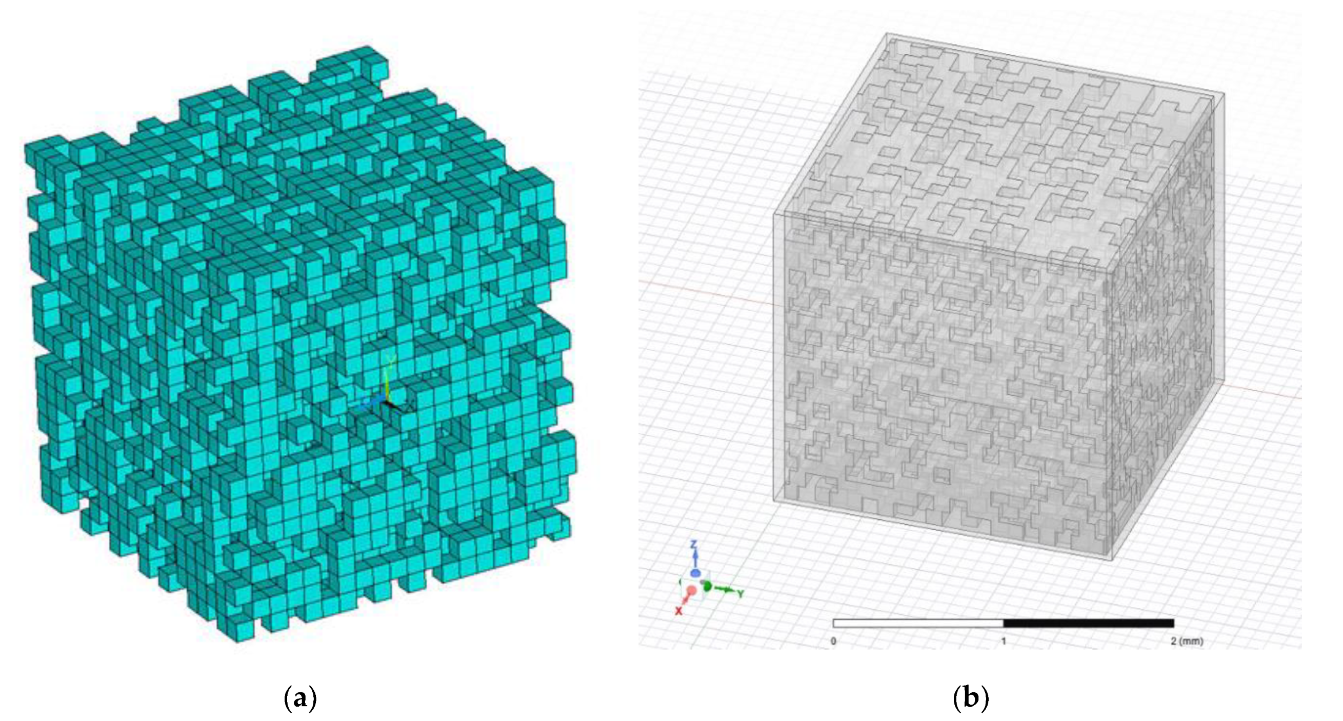
The first model was used in an ANSYS MECHANICAL EMAG environment (Figure 1a). The sample was divided into N = 8000 small cubic elements, with randomly defined material parameters. The magnetic field in the cube was created using appropriate boundary conditions. It employed the magnetic vector potential to enforce an average value of magnetic flux density Bavg along the chosen direction. For each distribution of elements, based on the assumed fill factor, a calculation was performed in one of the three directions.
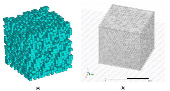
Figure 1.
Views of a FEM model of a sample made of ferromagnetic composite with magnetic powder and 50% fill factor: (a) in EMAG environment; (b) in AED environment.
The second model was created using ANSYS ELECTRONICS DESKTOP 2021 (Figure 1b, AED later in the text) computer program. This sample was divided into 0.1 mm × 0.1 mm × 0.1 mm cubes, resulting in a similar number of subregions as in the previous model. There were two differences that distinguish the AED model from the one used in EMAG:
- Subregions were not evenly distributed (as in the EMAG model) but rather organised in rows, with each row shifted from the nearest ones. Layers of such shifted rows were also shifted, resulting in a geometry in which every vertex belonged to only two subregions being neighbours in a row. Such a feature was necessitated by the handling of AED geometry—namely, the requirement to avoid non-manifold objects; however, it also introduced an irregularity to the net of ferromagnetic particles in the simulated sample. This irregularity was considered appropriate for simulating the stochastic distribution of particles in the sample.
- The magnetic field in the sample was produced by setting the appropriate boundary conditions: tangential “external” field intensity of value Hext on every side face of the sample, with the field intensity vector pointing upwards in the Z direction and 0-tangential field intensity on the bottom and top faces of the sample. A small offset was introduced between the side faces of the outer region and the actual sample to simplify the boundary condition and avoid very large values of the induced magnetic flux density in the ferromagnetic particles on the face of the sample. With such a setup, the sample was treated as being put in an external, uniform magnetic field.
Using the aforementioned models, a magnetisation curve (B-H curve) of the composite material was calculated, as it is the most useful characteristic from the application point of view. The characteristic was obtained in the average sense, i.e., the average values of B and H vectors in the sample were computed based on certain integral quantities. For a single point on the characteristic, the material was considered linear in the computation of average values, and the field distribution was assumed to be uniform, despite the fact that certain nonlinear phenomena (e.g., magnetic saturation) can occur locally. Two prepared models used two different methods in the calculation process.
In the EMAG model, an averaged value of flux density Bavg was enforced using appropriate boundary conditions in a pre-processor. Next, using the obtained FEM solution, a magnetic energy Emag was calculated in a post-processor as a sum of the magnetic energy Ek in every cubic subregion of the model. The resulting average value of field intensity Havg was then computed using the following equation:
where VCUBE is the volume of the whole magnetic composite sample. The obtained results using the above algorithm were also verified using Ampere’s law.
In the AED model, an averaged value of field intensity Havg was enforced using appropriate boundary conditions in the pre-processor. Next, using the obtained FEM solution, magnetic flux values ΦTOP and ΦBOT penetrating the top and bottom sides of the sample cube, respectively, were computed. The resulting average value of flux density Bavg was then calculated using the following equation:
where ACUBE is the area of the side of a sample cube, and is an average magnetic flux in the cube.
Both types of characteristics were compared, the results of which are presented in the next part of the paper.
2.3. Simulation Results
The described models were used to calculate B-H curves of a sample material for three values of fill factor: 10, 50, and 70%. The largest value was set to roughly correspond to the technological barrier—for fill factors greater than that, mechanical properties of the composite were not considered satisfactory (composites with nanoparticles can reach 68–74% fill factor depending on different factors according to [18]). The calculations were performed for the values of field intensity ranging from 0 to the value far in the saturation region of the B-H curve of the “base” ferromagnetic material. A low carbon 1010 steel was chosen as a base material for magnetic particles in the composite, as it has good magnetic properties that are well examined (its B-H curve is available in the ANSYS material library), is cheap, and available to purchase in a variety of forms (powder, wires).
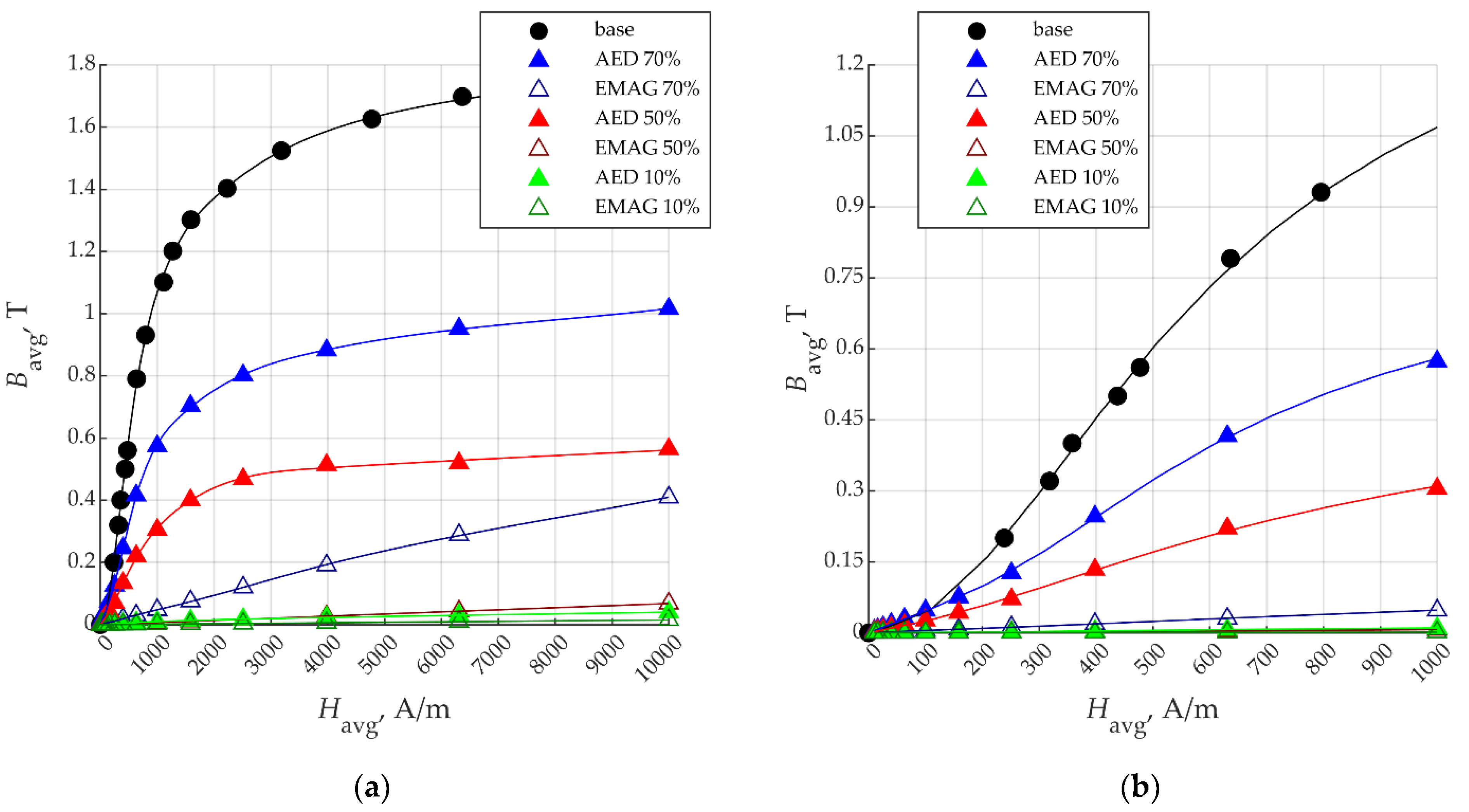
In Figure 2, the results of calculations are presented, both in the whole calculation range (a) and as a closeup (b) for relatively low values of magnetic field intensity. Results using two models are denoted as EMAG and AED, and “base” denotes the B-H curve of 1010 steel.
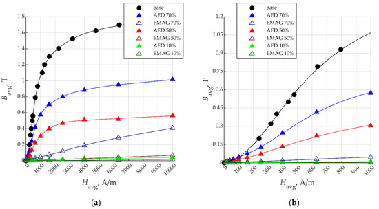
Figure 2.
B-H curves obtained for different fill factors in composite material using two models against the B-H curve of a 1010 steel (a) and its closeup (b).
The obtained results for a given fill factor differ strongly depending on the model used. Differences in data obtained using ANSYS EMAG and ANSYS MAXWELL packages might be the result of in-depth differences in their numerical procedures [24]. In the case of EMAG, using nodal-based SOLID97 element type, the unknown variable is the magnetic vector potential [25]. It was replaced in more modern approaches by direct evaluation of field variables (magnetic field intensity in MAXWELL) [26]. In relation to the presented models, it could result in very large differences since, in the case of EMAG, the value of magnetic flux density is obtained by space differentiation of , while in MAXWELL, it is directly evaluated based on B(H) curve [26].
According to the EMAG model, the characteristics of the composite are very bad in terms of its use in the construction of electromagnetic devices. In the whole considered range, they are linear, and relative permeability, even for a 70% fill factor, is approximately equal to 32, which is very poor for a magnetic material. On the other hand, the AED calculations are much more optimistic. According to them, the obtained characteristics resemble the scaled characteristic of a base material, e.g., for the fill factor equal to 70%, the scaling factor is approximately equal to 0.55 = 0.78 × [fill factor]. Such a behaviour can be explained by the fact that, for a given fill factor, only a portion of a cross-section of the sample made perpendicular to the flux lines, equal at most to the fill factor, can be made of ferromagnetic material. Additionally, in this model, the magnetic flux was located almost exclusively by the “chains” off ferromagnetic particles, forming randomly in the investigated sample. As it is unlikely that all the particles are arranged in such chains, the overall characteristics of a composite are worse than those of the apparent one, defined purely by a fill-factor value.
The obtained results with the MAXWELL model, however, should be treated rather as a best-case scenario—the complicated phenomena on the faces of ferromagnetic particles were omitted completely, and particle sizes were set to be larger than particle sizes of commonly used magnetic powders. Even with that, the following two key conclusions can be made:
- The composite material, even in the best case, has worse magnetic properties than those resulting from the value indicated by the fill factor, which should be the desired expectation (i.e., one should expect the characteristics of the composite to be the characteristics of a base material scaled by a fill factor);
- Drastically different results of calculations could indicate that several samples of the composite material with the same fill factor can have different magnetic properties based on random factors. This feature makes such a material unreliable, which is a considerable disadvantage if used in production.
3. Concept of a Magnetic Composite with Continuous Wires
3.1. Idea of the Composite
The new proposed material is to be manufactured using 3D printing and was expected to provide good magnetic properties. The idea of this magnetic material comes from the understanding of magnetic flux as a set of magnetic field force lines. Therefore, channels (fibres) made of ferromagnetic material need to be created for the flux.
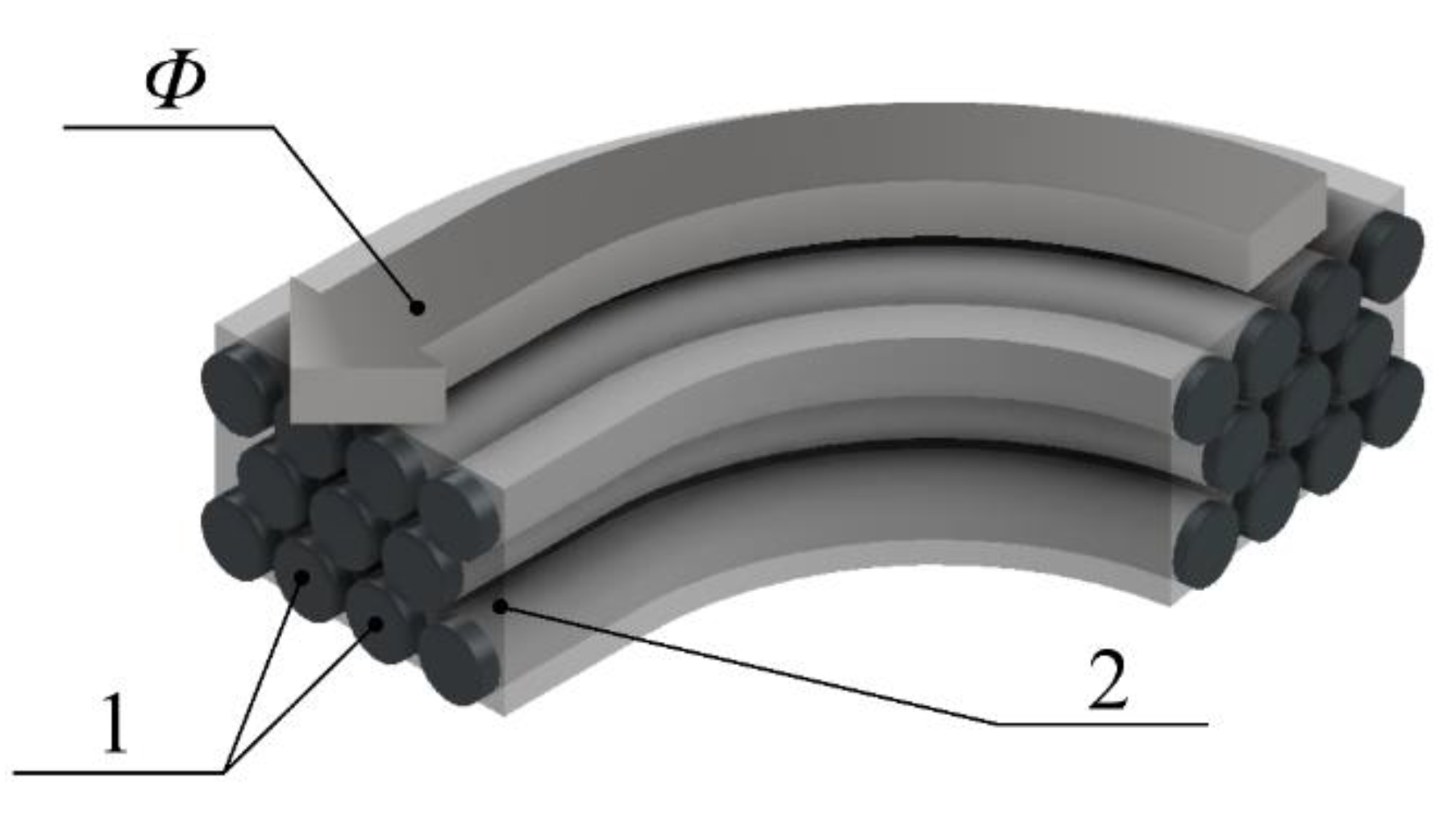
There are materials produced with 3D printing technology that contain continuous fibres that are not ferromagnetic [27]. Therefore, the plastic-continuous fibre composite material can be made using the FDM printing method, which prints continuous, fibre-reinforced parts. If instead of non-magnetic fibres, ferromagnetic wires are used, a new type of flux-conducting material is created (Figure 3).
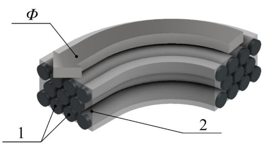
Figure 3.
The concept of composite magnetic material: 1—continuous fibres (ferromagnetic wires); 2—plastic; Φ—magnetic flux.
Figure 3 presents a section of the proposed material, which is a composite made of ferromagnetic wires in a plastic matrix.
Owing to the possibility of forming a path shape, which can be achieved using 3D printing FDM technology, ferromagnetic wires naturally can be shaped into the magnetic circuit by controlling the arrangement of the wires, i.e., channels for the magnetic flux Φ (Figure 3). Thus, 3D printing technology can produce a wire-based composite with good magnetic field conductivity in the direction formed during the printing process.
Manufacturing this material, which is a type of SMC, has typical characteristics of 3D printing and does not require a special chemical method or high temperature and pressure similar to those needed in, e.g., [20]. This is a clear advantage of the proposed approach from a technological point of view.
3.2. Magnetic Properties of the Composite Based on Simulation Results
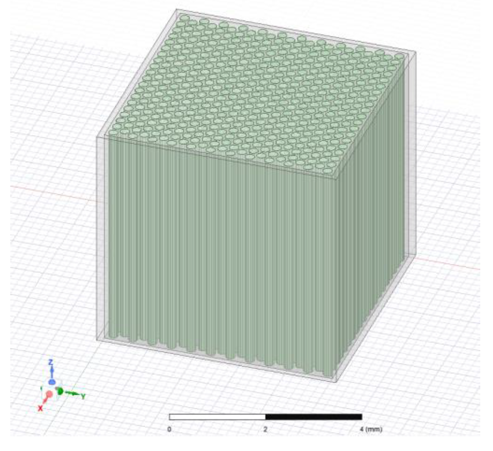
To properly assess the properties of a proposed wire-based composite, a FEM model was made. It is similar to the previously described AED mathematical model and consisted of a sample cube with the length of the edge equal to 5 mm, filled with a bundle of parallel wires (Figure 4). Wires were modelled as prisms with a base of regular dodecagon made of ferromagnetic material. A diameter of a wire was set to 0.2 mm. Prisms were used instead of (more appropriate) cylinders to simplify the geometry of a model, which significantly increased FEM calculation performance. The wires were spaced so that the centres of their bases were put in the knots of a grid made of regular triangles. Spaces between wires were calculated to match the desired fill factor.
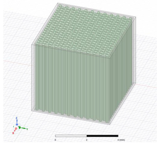
Figure 4.
A view of the mathematical model of a magnetic composite made of continuous wires, with the fill factor equal to 50%.
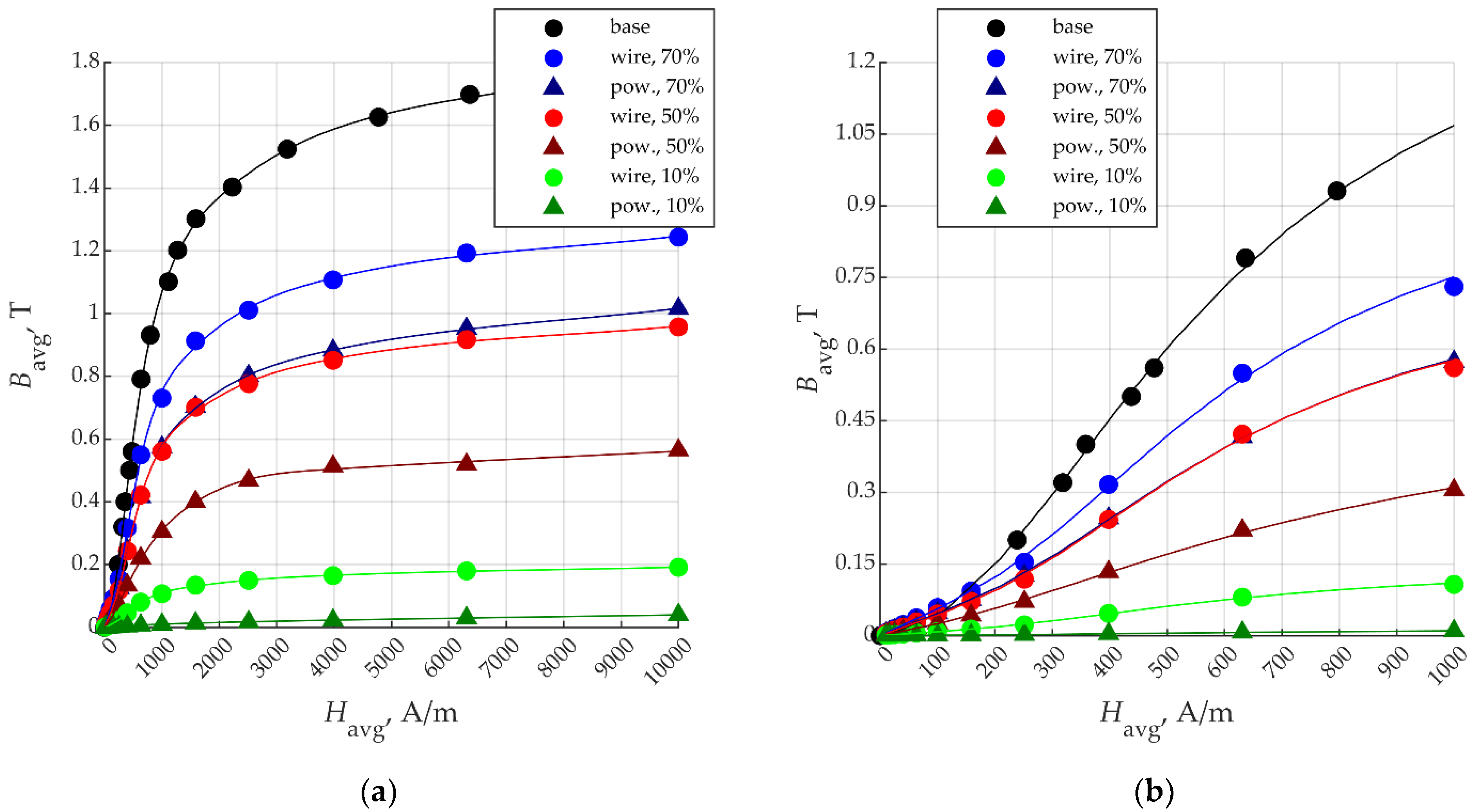
The model was prepared to calculate the properties of a composite with the same fill-factor values as those used in the models described in Section 2 (i.e., 10, 50, and 70%). The value of magnetic field intensity Havg was enforced, and the average value of magnetic flux density Bavg was calculated according to Equation (2). Wires were modelled to be built with steel 1010. The results of calculations were compared with those obtained using the AED model of the composite based on magnetic powder (denoted “pow”), and the B-H curve of the base material is shown in Figure 5. Values of basic magnetic properties of the simulated materials are presented in Table 1. The value of the saturation flux density is the value of flux density for which dynamic permeability is the lowest, and for the simulated composites, it occurred when magnetic field intensity was in the range between 8 kA/m to 9 kA/m. The maximum value of permeability occurred for magnetic field intensity value of approximately equal to 650 A/m.
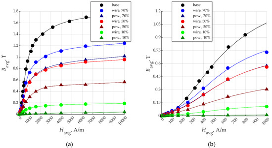
Figure 5.
B-H curves calculated for composites with continuous wires and different fill-factor values (a) and their closeup (b).

Table 1.
Values of the basic magnetic properties of the simulated composite materials.
Both magnetic permeability and the value of the saturation magnetic flux density were larger for the proposed material than those of the composite based on magnetic powder having the same fill factor. When aiming for desired values of those properties, this also means that there can be less ferromagnetic material used (leading to lighter material overall with more reinforcement material) in the proposed composite; for example, according to calculations, the wire-based composite with 50% fill factor had similar magnetic properties to the powder-based composite with a fill factor of 70%. It is worth noting that the difference in magnetic properties widened as the fill factor decreased. Such a property is expected, as for lower fill-factor values in powder-based composites, the paths for a magnetic flux made of ferromagnetic particles adhered to each other were less likely to occur. In Figure 5, it can also be observed that the B-H curves of the proposed composite materials were very close to the B-H curve of base material scaled by the fill factor. Such a property is expected and allows for precise control of the material properties in the construction phase and easy assessment of them once the material is produced. Calculated values are compared in Table 1, along with the properties of materials and composites reported in the literature (denoted with 1 in [28], 2 in [20], and 3 in [23]). Particularly interesting is a comparison with materials based on iron powder: a sintered iron powder, a composite made of iron powder, and an epoxy resin bonded under high pressure (for a composite mentioned in Table 1 weight of iron powder was set to 99,5% of a whole material, which corresponds to a fill factor of 96.6%) and a composite made of PLA and iron powder with fill factor 40%. The proposed wire-based composite was worse than the sintered material but could be considered comparable with the bonded one. At the same time, the obtained relative permeability value was better than that given for the “simple” PLA+iron powder composite. The authors of [23] do not give other magnetic parameters characterising the material, but even assuming linear characteristics (a very optimistic approach), the comparison indicates the superiority of the proposed composite over the traditional ones that are mixtures of polymers and magnetic powders.
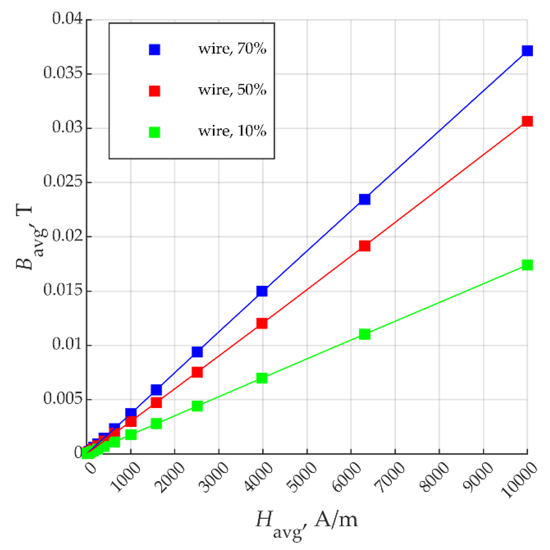
As seen in Figure 6, the material is predicted to be anisotropic regarding its magnetic properties. To confirm it, the calculations of B-H curves of the material were carried out once again but with the magnetic field enforced perpendicular to the wires. The results of the calculations are presented in Figure 6. Indeed, the material was almost diamagnetic when magnetised in this direction. Such a feature, in some cases, can also be an advantage—there are many electromagnetic devices in which paths of the magnetic flux are desired to be strictly determined. The proposed composite would allow the easier achievement of such a goal.
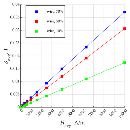
Figure 6.
B-H curves of the proposed wire-based composite with the magnetisation direction perpendicular to the wires.
4. Discussion and Further Research
In this paper, the concept of a new ferromagnetic composite material based on continuous wires of ferromagnetic material was described. A study on this material is reasoned by the strong demand for a ferromagnetic composite that is suitable for additive manufacturing, especially as currently available composites based on magnetic powders do not reveal satisfying properties, either magnetic or mechanical.
The composite was designed so that it “sets up” a path for magnetic flux produced in the sample. This general idea was derived from the requirements imposed on magnetic circuits in electrical machinery, the production of which was considered a key application of the proposed material. In such devices, the force lines of the magnetic field were meant to be strictly specified curves by the constructor. A proposed composite can cause such a behaviour of the magnetic field by precise forming of the material from which a device is made.
Using a FEM mathematical model, the proposed wire-based composite was compared with a powder-based one, and it was also suited to additive manufacturing. In each model, a used ferromagnetic material was modelled to have a magnetisation characteristic similar to that of common low-carbon steel. The magnetisation characteristics of the examined composites were calculated and compared. The model of a powder-based composite was simplified due to the limitations of the FEM method, and to better assess the properties of this material, two models using different strategies were made. Only the best-obtained results regarding the powder-based composite (i.e., those that indicated the highest values of permeability and saturation flux density) were taken into account for the comparison. The calculations for several fill factors (i.e., the ratio of the volume of a ferromagnetic part of the material to its whole volume) show that, in every case, the proposed wire-based composite had better magnetic properties, and such a result was more evident as the fill factor decreased. Furthermore, the calculated magnetic properties of the wire-based composite are easily explained and relatively directly depend on the fill factor and the B-H curve of a base ferromagnetic material, which makes the whole composite reliable. The proposed composite also showed a strong magnetic anisotropy, making the preferred magnetic flux path in the produced magnetic circuit even more evident. On the other hand, currently developed ferromagnetic composites reported in the literature have better magnetic properties than those calculated and presented in this paper while maintaining good mechanical properties. However, the technology of producing such composites, made with ferromagnetic powders, includes sintering or bonding under high pressure; therefore, it is not suited to be used in additive manufacturing. In this light, a proposed composite, while not ideal, could find its niche in rapid prototyping or small-scale production of magnetic circuits.
The authors believe that such a feature will be especially important in the production of small electrical machines and energy harvesters. Experimental verification of the presented results will be the topic of our future research. The magnetic properties of the proposed wire-based composite can be investigated by testing a toroid sample made of the composite. It could be a test of a single-wound toroid (currently a decay method) or a double-wound toroid (transformer method).
5. Conclusions
The paper can be concluded by the following findings:
- Magnetic composites currently developed for additive manufacturing are usually a mixture of magnetic powder and polymer. Without taking special measures (e.g., bonding under high pressure), their magnetic characteristic is poor because relatively low values of the ratio of magnetic particles’ volume to the whole composite volume (named fill factor) are achievable using available materials and technology, as well as the low utilisation of the ferromagnetic material caused by the random distribution of magnetic particles in the composite.
- In this paper, a novel magnetic composite suited for 3D printing was proposed. It is made of wires of ferromagnetic material immersed in a certain polymer. Wires were arranged along the desired flux lines in the constructed magnetic circuit.
- The proposed composite was compared with a composite based on magnetic powder for several fill-factor values by the means of FEM analysis. Models regarding the powder-based composite returned different values of the computed values, depending on the numerical method used in calculations, but for comparison purposes, only the best-case scenario was used. The analysis proved the proposed solution to be superior for all fill-factor values examined. The comparison was leaning stronger towards the wire-based composite for lower values of the fill factor.
6. Patent
The proposed magnetic composite based on continuous wires is a subject of a patent request, registered by a Polish patent office with the number P.440090.
Author Contributions
Conceptualisation, all authors; methodology, W.B. and P.K.; mathematical modelling, W.B. and Z.K.; formal analysis, P.K.; computations, data curation, and investigation, Z.K.; resources, R.M.; writing—original draft preparation, W.B., Z.K., P.K., and R.M.; writing—review and editing, R.M. and W.B.; visualisation, Z.K. All authors have read and agreed to the published version of the manuscript.
Funding
This research received no external funding.
Data Availability Statement
Data is contained within the article or supplementary material.
Conflicts of Interest
The authors declare no conflict of interest.
References
- Bito, J.; Bahr, R.; Hester, J.G.; Nauroze, S.A.; Georgiadis, A.; Tentzeris, M.M. A Novel Solar and Electromagnetic Energy Harvesting System With a 3-D Printed Package for Energy Efficient Internet-of-Things Wireless Sensors. IEEE Xplore 2017, 65, 1831–1842. [Google Scholar] [CrossRef]
- Périgo, E.A.; Jacimovic, J.; García Ferré, F.; Scherf, L.M. Additive manufacturing of magnetic materials. Addit. Manuf. 2019, 30, 100870. [Google Scholar] [CrossRef]
- Dong, B.; Qin, W.; Su, Y. Magnetic properties of FeSiCr@MgO soft magnetic composites prepared by magnesium acetate pyrolysis for high-frequency applications. J. Magn. Magn. Mater. 2021, 539, 168350. [Google Scholar] [CrossRef]
- Zang, C.; Zang, W.; Yuan, W. Preparation and magnetic properties of core-shell structured Fe-Si/Fe3O4 composites via in-situ reaction method. J. Magn. Magn. Mater. 2021, 531, 167955. [Google Scholar] [CrossRef]
- Shi, X.; Chen, X.; Wan, K. Enhanced magnetic and mechanical properties of gas atomized Fe-Si-Al soft magnetic composites through adhesive insulation. J. Magn. Magn. Mater. 2021, 534, 168040. [Google Scholar] [CrossRef]
- Yi, X.; Peng, Y.; Yao, Z. Microstructure and magnetic properties of FeSiAl soft magnetic composites prepared by chemical in-situ coprecipitation with NaOH. Mater. Chem. Phys. 2021, 267, 124626. [Google Scholar] [CrossRef]
- Bircakova, Z.; Onderko, F.; Dobak, S. Eco-friendly soft magnetic composites of iron coated by sintered ferrite via mechanofusion. J. Magn. Magn. Mater. 2022, 546, 168627. [Google Scholar] [CrossRef]
- Luo, Z.; Fan, X.; Zhang, Y. Formation mechanism and magnetic performance of Fe-Si soft magnetic composites coated with MnO-SiO2 composite coatings. Adv. Powder Technol. 2021, 32, 3364–3371. [Google Scholar] [CrossRef]
- Ma, R.; Yu, P. The influences of matrix materials on the magnetic and mechanical properties of Fe78Si9B13 soft magnetic composites fabricated by injection molding. Mater. Reser. Bull. 2021, 139, 111256. [Google Scholar] [CrossRef]
- Zhang, J.; Wang, Z.; Li, J. Magnetic-electric composite coating with oriented segregated structure for enhanced electromagnetic shielding. J. Mater. Sci. Technol. 2022, 96, 11–20. [Google Scholar] [CrossRef]
- Wang, L.; Dong, Y.; Chang, L. High performance of Fe-based soft magnetic composites coated with novel nano-CaCO3/epoxy nanocomposites insulating layer. J. Solid State Chem. 2021, 304, 122634. [Google Scholar] [CrossRef]
- Neamtu, B.V.; Pszola, M.; Vermesan, H. Preparation and characterisation of Fe/Fe3O4 fibres based soft magnetic composites. Ceram. Int. 2021, 47, 581–589. [Google Scholar] [CrossRef]
- Chang, J.; Zhan, T.; Peng, X. Improved permeability and core loss of amorphous FeSiB /Ni-Zn ferrite soft magnetic composites prepared in an external magnetic field. J. Alloy. Comp. 2021, 886, 161335. [Google Scholar] [CrossRef]
- Błyskun, P.; Kowalczyk, M.; Łukaszewicz, G. Influence of particles size fraction on magnetic properties of soft magnetic composites prepared from a soft magnetic nanocrystalline powder with no synthetic oxide layer. Mater. Sci. Eng. B 2021, 272, 115357. [Google Scholar] [CrossRef]
- Taghvaei, A.H.; Mazaleyrat, F.; Eckert, J. Fabrication and characterization of novel soft magnetic [(Fe0.7Co0.3)71.2B24Y4.8]96Nb4/V2O5 bulk metallic glassy/composite cores with excellent magnetic permeability and low core losses. J. Alloy. Comp. 2020, 846, 156427. [Google Scholar] [CrossRef]
- Liu, S.; Zou, H.; Qin, B. Tailored magnetoelectric coupling in magnetically oriented polymer-based iron fiber composite. J. Magn. Magn. Mater. 2021, 540, 168408. [Google Scholar] [CrossRef]
- Kania, A.; Berent, K.; Mazur, T. 3D printed composites with uniform distribution of Fe3O4 nanoparticles and magnetic shape anisotropy. Addit. Manuf. 2021, 46, 102149. [Google Scholar] [CrossRef]
- Wang, Y.; Castels, F.; Grant, P.S. 3D Printing of NiZn ferrite/ABS Magnetic Composites for Electromagnetic Devices. Mater. Res. Soc. Symp. Proc. 2015, 1788, 29–35. [Google Scholar] [CrossRef]
- Yang, T.; Lu, K.; Wang, J.; Xu, J.; Zheng, Z.; Liu, X. Fe-6.5 wt%Si soft magnetic composites with significant improvement of magnetic properties by compositing nano-MnZn ferrites. J. Alloy. Compd. 2022, 909, 164660. [Google Scholar] [CrossRef]
- Ferraris, L.; Franchini, F.; Pošković, E.; Actis Grande, M.; Bidulský, R. Effect of the Temperature on the Magnetic and Energetic Properties of Soft Magnetic Composite Materials. Energies 2021, 14, 4400. [Google Scholar] [CrossRef]
- Xiao, L.; Ying, Y.; Zheng, J. Hybrid amorphous soft magnetic composites with ultrafine FeSiBCr and submicron FeBP particles for MHz frequency power applications. J. Magn. Magn. Mater. 2022, 169365. [Google Scholar] [CrossRef]
- Ni, J.L.; Duan, F.; Feng, S.J. High performance of FeSiAl/hBN soft magnetic composites. J Alloy. Compd. 2022, 897, 163191. [Google Scholar] [CrossRef]
- Vincent, M.; Frédéric, G.; Denis, N.; Abdelkader, B.; Jean-François, W.; Michel, H.; Philippe, Q. Additive Manufacturing for Soft Magnetic Materials. In Proceedings of the 2021 IEEE International Magnetic Conference (INTERMAG), Lyon, France, 26–30 April 2021. [Google Scholar]
- Meunier, G. The Finite Element Method for Electromagnetic Modeling; John Wiley & Sons, Inc.: London, UK, 2008. [Google Scholar]
- Gyimesi, M.; Ostergaard, D. Non-conforming hexahedral edge elements for magnetic analysis. IEEE Trans. Magn. 1998, 34, 2481–2484. [Google Scholar] [CrossRef]
- Lee, J.F.; Sun, D.K.; Cendes, Z.J. Tangential vector finite elements for electromagnetic field computation. IEEE Trans. Magn. 1991, 27, 4032–4035. [Google Scholar] [CrossRef]
- Mark, G.T.; Gozdz, A.S. Three Dimensional Printer for Fiber Reinforced Composite Filament Fabrication. U.S. Patent 9,126,367, 7 September 2015. [Google Scholar]
- Fulay, P. Electronic, Magnetic and Optical Materials; CRC Press: Boca Raton, FL, USA, 2010. [Google Scholar]
Publisher’s Note: MDPI stays neutral with regard to jurisdictional claims in published maps and institutional affiliations. |
© 2022 by the authors. Licensee MDPI, Basel, Switzerland. This article is an open access article distributed under the terms and conditions of the Creative Commons Attribution (CC BY) license (https://creativecommons.org/licenses/by/4.0/).