Article

Performance Analysis of Anti-Interference Cooperative NOMA System for Aviation Data Links

School of Information and Navigation, Air Force Engineering University, Xi’an 710077, China
*
Author to whom correspondence should be addressed.
Electronics 2023, 12(10), 2182; https://doi.org/10.3390/electronics12102182
Submission received: 29 March 2023 / Revised: 3 May 2023 / Accepted: 9 May 2023 / Published: 10 May 2023
(This article belongs to the Special Issue Advances in Electromagnetic Interference and Protection)

Abstract

:
In collaborative combat operations, the challenges posed by communication adversities in aviation data links have become increasingly conspicuous. Ensuring the reliable connectivity of data links has thus emerged as a critical issue, particularly in light of growing interference effects on communication link outage. To address this challenge, this paper proposes a cooperative non-orthogonal multiple access (NOMA) technology that aims to enhance interference tolerance and strengthen stable communication capabilities in data links. To achieve these goals, an anti-interference collaborative NOMA system model applicable to aviation data links is established, and the anti-interference performance of collaborative NOMA technology is analyzed under Rice fading channel conditions. The analysis centers on the system’s outage probability, for which a closed-form expression is derived. Numerical analysis methods are employed to calculate and solve the expression, while simulation experiments are conducted to analyze the effect of factors such as transmission power, cooperative forwarding power, interference power, communication distance, and allocation coefficients on the system’s outage probability. The results show that the aviation data link system using a collaborative NOMA scheme has better anti-interference performance than a non-collaborative scheme, and adjusting the above parameters can effectively improve the system’s stable communication performance.

1. Introduction

Air combat is expected to evolve into a game-like confrontation that heavily relies on intelligence and information [1]. The battlefield environment will be dynamic, and situational information will increase exponentially [2]. As a result, there will be greater demands for throughput, high bandwidth efficiency, low latency, and survival capabilities of aviation data link systems in complex electromagnetic environments. Therefore, the design, analysis, and evaluation of the anti-interference performance and channel resource utilization efficiency of these systems become critical.
Several optimization strategies have been proposed to enhance channel resource utilization efficiency [3,4,5]. However, most of these strategies are based on orthogonal multiple access technology, which creates a bottleneck in further progress. To overcome this limitation and meet the upcoming requirements of future battlefield communication systems, NOMA technology can be introduced. This technology achieves simultaneous frequency sharing of channel resources among multiple users, significantly improving spectral efficiency [6].
Numerous research studies have laid the foundation of NOMA technology, with references [7,8,9,10,11,12,13] providing a comprehensive overview of its advantages and exploring its integration potential with modern wireless communication technologies such as MIMO, SCMA, and Cooperative Communication. These references also emphasize the critical role of successive interference cancellation (SIC) techniques in NOMA systems. References [14,15] investigate combining MIMO with downlink NOMA and propose user-assisted cooperative relay schemes for “beam-space massive MIMO (M-MIMO) NOMA systems”. Reference [16] employs innovative cognitive radio NOMA (CR-NOMA) technology that leverages fuzzy logic-based power allocation to improve bit error rate (BER). However, these studies did not delve into the specific performance metrics of NOMA systems. In contrast, reference [17] proposes an adaptive power allocation technique based on fuzzy logic (FL) to improve system performance by analyzing user rate fairness and system interruption probability, while references [18,19,20,21,22] provide a comprehensive analysis of several performance metrics, including fault probabilities, security, and data transmission rates, and ensure system security and speed. In particular, reference [23] discusses the interruption probability and diversity order of cooperative NOMA schemes and finds that they can enhance system stability. Therefore, this study aims to explore the potential of incorporating cooperative NOMA technology into aviation data link systems to improve their anti-interference capability and overall performance.
Traditional anti-interference techniques, such as frequency hopping, spread spectrum, and frequency-hopping spread spectrum techniques, have been widely used to enhance the performance of data link systems [24]. However, in recent years, a growing body of literature has proposed innovative approaches to address the limitations of these conventional methods. For instance, Cognitive Hopping Frequency (CHF) and software-defined radio technologies have been employed to dynamically adjust system parameters and improve interference tolerance [25,26]. Additionally, researchers have proposed schemes based on random spreading and parallel logarithmic linear learning algorithms to optimize bit error rates and reduce communication interference among users [27]. These studies have focused on orthogonal multiple access (OMA) technology to optimize data link stability. To further enhance the anti-interference capability of data link systems, NOMA technology has been introduced as an alternative approach. Specifically, reference [28] proposes an aviation data link system model based on NOMA technology under interference (ADLS-NOMA-I), optimized for the characteristics of aviation cluster battlefields. The model analyzes the interruption probability of the aviation data link based on NOMA technology under interference and explores the impact of factors such as signal transmission power, transmission distance, and enemy interference on system performance. This study provides an important reference for the design and optimization of aviation data link systems.
This paper optimized and improved the model in reference [28], proposing an anti-interference cooperative NOMA system model to further enhance the stability of the system. The proposed model enables aircraft formations with better channel quality to decode and forward necessary command information to formations with poorer channel quality and stronger interference. This cooperative scheme provides an additional chance for aircraft formations with poor channel quality to receive signals, allowing them to decode signals with stronger signal-to-noise ratios and reduce the interruption probability at the receiving end, thereby improving the stability of the aviation data link system. Finally, through simulation analysis, it was verified that the cooperative NOMA system proposed in this paper has better anti-interference performance than the non-cooperative NOMA system in reference [28].

2. System Model

2.1. Scenario Assumptions

This study proposes the implementation of cooperative NOMA technology to enhance interference tolerance and stability in aviation data link systems during the collaborative combat phase. Enemy interference in aircraft formation communication can increase the outage probability. Therefore, NOMA technology is adopted between the Airborne Warning and Control System (AWACS) and each aircraft formation to improve resource utilization efficiency. Orthogonal multiple access technology is used within each aircraft formation.
As depicted in Figure 1, during a mission, the AWACS needs to transmit different tactical commands simultaneously to the leading aircraft of multiple formations. Formations A and B are located at varying distances from point S, with formation B being closer to the jamming source R that continuously emits interference signals. Due to the complex electromagnetic environment and high traffic on the battlefield, cooperative NOMA technology is employed to mitigate the effects of interference. Two user signals are superimposed to reduce decoding complexity at the receiving end when multiple users are present. Signals from different groups use OMA for pairing and superposition.
The utilization of cooperative NOMA technology enables the aircraft formation, which has poor channel quality and a long distance, to receive two messages containing their own instructions in two different time slots. By comparing the outage performance of the two signals, this formation selects the one with better outage performance, thereby reducing the system’s outage probability [29].

2.2. The Anti-Interference Cooperative NOMA System Model for Aviation Data Links

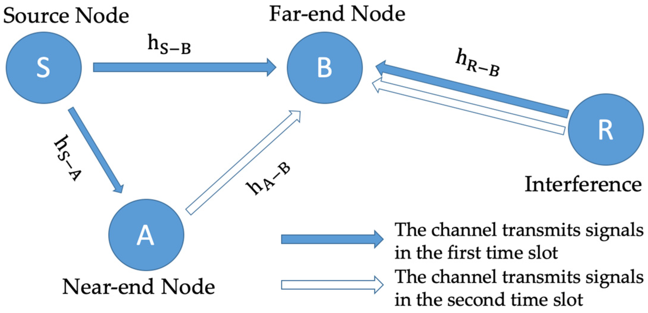
This section focuses on the discussion of one group of the cooperative process, namely the pairing between aircraft formation A and B. Formed in response to the scenario assumptions, node S is situated closer to formation A, while formation B suffers from interference due to its distance from the signal source. To mitigate the effects of interference, a cooperative scheme is adopted.
The abstract topology diagram (Figure 2) illustrates the transmission signal node S as AWACS, with the near-end node A and far-end node B representing the leading aircraft of formations A and B, respectively. The interference node R is an interfering aircraft, and hi denotes the respective channels between each node. This pairing enables the two aircraft formations to leverage cooperative NOMA technology for communication with the AWACS, thereby improving resource utilization efficiency and reducing outage probability.
Due to the high-speed movement and special spatial environment of aircraft, the Rician fading model is more suitable for aircraft communication links [28]. Therefore, in this article, all channel models are based on the Rician fading model, which can better describe the multipath effect of aircraft communication links and provide more accurate analysis of signal propagation and fading. This can help to design and optimize communication systems and improve communication quality and reliability.

2.2.1. Description of the Cooperative Process

In the first time slot, the transmission signal node S combines the instruction signals x 1 ( t ) and x 2 ( t ) intended for aircraft formations A and B, respectively, using selection combining (SC) multiplexing technique, and simultaneously transmits them to the near-end node A and the far-end node B. The transmission signal x s ( t ) of node S can be expressed as [28]
x s ( t ) = α 1 P s x 1 ( t ) + α 2 P s x 2 ( t ) ,
where α 1 and α 2 represent the power allocation coefficients for x 1 ( t ) and x 2 ( t ) , respectively, and α 1 + α 2 . Since formation A is closer to S and has better channel conditions, a smaller power is allocated to x 1 ( t ) , i.e., α 2 > α 1 . P s is the transmission power of S, E   [ | x 1 ( t ) | 2 ]   = 1 ,   E   [ | x 2 ( t ) | 2 ] = 1 . The signal received by formation A from S can be expressed as y A ( t ) .
y A ( t ) = h 1 ( t ) ( α 1 P s x 1 ( t ) + α 2 P s x 2 ( t ) ) + n 0 ( t ) ,
where h 1 ( t )   is the channel gain between S and A, and   n 0 ( t ) ~(0, σ 0 2 ) is the white Gaussian noise. Since formation A is closer to S, it decodes the stronger signal x 2 ( t ) in the first time slot and forwards it to formation B with a power of P A in the second time slot. At the same time, x 2 ( t ) is removed and reconstructed from the original signal y A ( t ) , and the reconstructed signal is denoted as y A 1 ( t ) .
y A 1 ( t ) = h 1 ( t ) α 1 P s x 1 ( t ) + n 1 ( t ) ,
where n 1 ( t ) ~(0, σ 0 2 ) is the white Gaussian noise. Since formation B is farther away from S, it receives not only the broadcast signal from S in the first time slot, but also the interference signal x R ( t ) from the enemy interference source R with a transmission power of P R . The signal received by formation B can be expressed as y B 1 ( t ) .
y B 1 ( t ) = h 2 ( t ) ( α 1 P s x 1 ( t ) + α 2 P s x 2 ( t ) ) + h 4 ( t ) P R x R ( t ) + n 2 ( t ) ,
where h 2 ( t ) is the channel gain between S and B,   h 4 ( t ) is the channel gain between R and B, and n 2 ( t ) ~(0, σ 0 2 ) is the white Gaussian noise. In the second time slot, formation B receives the signal x 2 ( t ) forwarded by A with a power of P A , and is also subject to the interference signal x R ( t ) from the enemy interference source R. The signal received by formation B in the second time slot can be expressed as y B 2 ( t ) .
y B 2 ( t ) = h 3 ( t ) P A x 2 ( t ) + h 4 ( t ) P R x R ( t ) + n 3 ( t ) ,
where h 3 ( t ) is the channel gain between formations A and B, and n 3 ( t ) ~(0, σ 0 2 ) is the white Gaussian noise.

2.2.2. Channel Capacity

Based on the cooperative process described in the previous section, the channel capacities of nodes A, B, and the entire system can be expressed first to facilitate the derivation of the closed-form expression for the outage probability. This article does not consider the impact of shadow fading on the derivation of the system’s channel capacity because, in open areas, the variation of shadow fading is slow and can be considered as a constant, so its impact can be ignored. Therefore, the channel gain h i ( t ) can be expressed as
h i ( t ) = d i ( t ) γ g i ( t ) ,
where d i ( t ) γ is the path loss coefficient, d i ( t ) is the distance between aircraft formations, γ is the path loss exponent, and g i ( t ) represents the Rician fading coefficient. In the following formulas, h i is used to represent h i ( t ) , and d i is used to represent d i ( t ) .
In the anti-interference cooperative NOMA system, the signal   y A ( t ) received by formation A in the first time slot contains both x 1 ( t ) and x 2 ( t ) . To decode the signal x 2 ( t ) with a larger power allocation coefficient using the SIC technique, x 1 ( t ) needs to be treated as noise. According to Shannon’s theorem, the decoding channel capacity C A 1   can be expressed as
C A 1 = log 2 ( 1 + α 2 P S | h 1 | 2 α 1 P S | h 1 | 2 + δ 2 ) .
After decoding the signal x 2 ( t ) from the original signal, the signal is removed and reconstructed. The decoding channel capacity for x 1 ( t ) can be expressed as
C A 2 = log 2 ( 1 + α 1 P S | h 1 | 2 δ 2 ) .
The signal y B 1 ( t ) received by formation B in the first time slot contains x 1 ( t ) ,     x 2 ( t ) , and the interference signal from the enemy. Since formation B needs to decode the signal with a larger power allocation coefficient, it can use the SIC technique to directly decode x 2 ( t ) , treating x 1 ( t ) and the enemy interference as noise. The decoding channel capacity is expressed as
C B 1 = log 2 ( 1 + α 2 P S | h 2 | 2 α 1 P S | h 2 | 2 + P R | h 4 | 2 + δ 2 ) .
The signal y B 2 ( t ) received by formation B in the second time slot contains the decoded and forwarded signal x 2 ( t ) from formation A with its own power and the interference signal from the enemy. The decoding channel capacity is expressed as
C B 2 = log 2 ( 1 + P A | h 3 | 2 P R | h 4 | 2 + δ 2 ) .
Formation B adopts the SC method to process the signals received in two time slots, i.e., selecting the maximum channel capacity. This can be expressed as
C B = max { C B 1 , C B 2 } .
The information channel capacity of the entire air data link system can be expressed as
C 0 = min { C A 1 , C A 2 , C B } .

3. Outage Probability

In the study of NOMA systems, outage probability is a widely used metric for assessing system stability. An outage event occurs in the system when the channel capacity of a node falls below a threshold value R, as represented by the outage probability distribution. In the model proposed in this paper, the possibility of outage events occurring in the system is considered with respect to two nodes.
(1)
At node A.
The channel capacity C A 1 for decoding x 2 ( t ) at node A is less than R, and the channel capacity C A 2 for decoding its own instruction signal x 1 ( t ) after signal reconstruction is also less than R. The outage probability P out A can be expressed as
P out A = Pr { min { C A 1 , C A 2 } < R } .
(2)
At node B.
If the channel capacity C B 1 for decoding x 2 ( t ) at node B is less than R or the channel capacity C B 2 for decoding x 2 ( t ) after signal reconstruction is less than R, an outage event will occur at node B. The outage probability P out B can be expressed as
P out B = Pr { max { C B 1 , C B 2 } < R } .
Therefore, the outage probability P out for the channel capacity C 0 of the entire system being less than R can be expressed as
P out = Pr { C 0 < R }   = Pr { min { C A , C B } < R } = Pr { log 2 ( 1 + min { α 2 P S | h 1 | 2 α 1 P S | h 1 | 2 + δ 2 , α 1 P S | h 1 | 2 δ 2 , max { α 2 P S | h 2 | 2 α 1 P S | h 2 | 2 + P R | h 4 | 2 + δ 2 , P A | h 3 | 2 P R | h 4 | 2 + δ 2 } } ) < R } = 1 Pr ( R 1 2 R 1 ) Pr ( R 2 2 R 1 )   [ 1 Pr ( R 3 < 2 R 1 ) Pr ( R 4 < 2 R 1 ) ] ,
where R 1 = α 2 P S | h 1 | 2 α 1 P S | h 1 | 2 + δ 2 ,   R 2 = α 1 P S | h 1 | 2 δ 2 ,   R 3 = α 2 P S | h 2 | 2 α 1 P S | h 2 | 2 + P R | h 4 | 2 + δ 2 ,   R 4 = P A | h 3 | 2 P R | h 4 | 2 + δ 2 .
P out = 1 Pr ( R 1 2 R 1 ) Pr ( R 2 2 R 1 ) [ 1 Pr ( R 3 < 2 R 1 ) Pr ( R 4 < 2 R 1 ) ] .
In the scenario set in this paper, the link attenuation between aircraft formations is considered to be Rayleigh fading. The probability distribution P h i ( x ) of the small-scale fading coefficient g i and the channel fading coefficient h i can be expressed as
P h i ( x ) = { d i γ 2 δ i 2 exp ( x 2 d i 2 γ + ρ i 2 2 δ i 2 ) I 0 ( x ρ i d i γ δ i 2 )   x 0 0   x < 0 ,
where I 0 ( · ) is the modified Bessel function of the first kind, δ i 2 is the power of the multipath component signal in Rayleigh channel, and ρ i 2 is the peak value of the line-of-sight signal. After transforming the independent variable, we can derive P | h i | 2 ( x ) as [28]
P | h i | 2 ( x ) = { d i γ 2 δ i 2 exp ( x d i γ + ρ i 2 δ i 2 ) I 0 ( x d i γ ρ i δ i 2 )   x 0 0   x < 0 .
To simplify the calculation, we first solve each probability distribution function separately by letting
F 1 ( r ) = Pr ( R 1 r ) = Pr { | h 1 | 2 < σ 2 α 2 P s r α 1 P s } = 0 r α 1 P s r α 2 P s P | h 1 | 2 ( x ) d x ,
F 2 ( r ) = Pr ( R 2 r ) = Pr { | h 1 | 2 < σ 2 x α 1 P s } = 0 σ 2 x α 1 P s P | h 1 | 2 ( x ) d x ,
F 3 ( r ) = Pr ( R 3 r ) = Pr { P A | h 3 | 2 P R | h 4 | 2 + σ 2 r } .
As the channels h 3 and h 4 are independent, we have
f 3 ( x 3 , x 4 ) = P | h 3 | 2 ( x 3 ) P | h 4 | 2 ( x 4 ) ,
F 3 ( r ) = Pr { P A | h 3 | 2 r σ 2 r P R | h 4 | 2 } = 0 0 r σ 2 + r P R x 4 P A f ( x 3 , x 4 ) d x 3 d x 4 ,
F 4 ( r ) = Pr ( R 4 r ) = Pr { α 2 P s | h 2 | 2 α 1 P s | h 2 | 2 + P R | h 4 | 2 + σ 2 r } .
Similarly, as the channels h 2 and h 4 are independent, we have
f 4 ( x 2 , x 4 ) = P | h 2 | 2 ( x 2 ) P | h 4 | 2 ( x 4 ) ,
F 4 ( r ) = 0 0 r σ 2 + r P R x 4 α 2 P s r α 1 P s f ( x 2 , x 4 ) d x 2 d x 4 = 0 P | h 4 | 2 ( x 4 ) 0 r σ 2 + r P R x 4 α 2 P s r α 1 P s P | h 2 | 2 ( x 2 ) d x 2 d x 4 .
Since the four formulas mentioned above are difficult to solve directly, this paper uses the composite five-point Gauss–Legendre formula and the Gauss–Laguerre formula to solve the integrals, where F 1 ( r ) and F 2 ( r ) . are single integrals that can be directly solved using the Gauss–Legendre formula:
F k ( r ) b a 2 n i = 1 n j = 1 m A j f k ( b a 2 n x j + b + a 2 n + b a n i ) ,
where n = 50 is the number of sub-intervals and m = 5 is the number of Gaussian nodes in each interval. A j is the weight value of the Gaussian quadrature formula, and x j is the corresponding Gaussian node associated with the weight value. The upper limit of integration b is given by b = r α 1 P s r α 2 P s , and the lower limit a is 0 for F 1 ( r ) . We have f 1 ( x ) = P | h 1 | 2 ( x ) . Similarly, for F 2 ( r ) , we have b = σ 2 x α 1 P s , a = 0 , and f 2 ( x ) = P | h 1 | 2 ( x ) .
For F 3 ( r ) and F 4 ( r ) , which are double integrals with infinite limits, we first use the Gauss–Legendre formula to obtain the inner integral as follows:
F 3 ( r )   0 P | h 4 | 2 ( x 4 )   [ b a 2 n i = 1 n j = 1 m A j P | h 3 | 2 ( b a 2 n x j + b + a 2 n + b a n i ) ] d x 4 = 0 e x 4 e x 4 P | h 4 | 2 ( x 4 )   [ b a 2 n i = 1 n j = 1 m A j P | h 3 | 2 ( b a 2 n x j + b + a 2 n + b a n i ) ] d x 4 = 0 e x 4 e x 4 I 3 ( x 4 ) d x 4 .
where   I 3 ( x 4 ) = P | h 4 | 2 ( x 4 )   [ b a 2 n i = 1 n j = 1 m A j P | h 3 | 2 ( b a 2 n x j + b + a 2 n + b a n i ) ] , b = r σ 2 + r P R x 4 P A , a = 0 , n = 50 , and m = 5 . After obtaining the inner integral using the Gauss–Legendre formula, we use the Gauss–Laguerre formula to obtain the second infinite integral for F 3 ( r ) as
F 3 ( r ) = 0 e x 4 I 3 ( x 4 ) d k = 1 l w k I 3 ( x 4 k ) ,
where l = 6 is the number of Gauss–Laguerre nodes used for numerical integration. w k are the weight and x j are the corresponding nodes obtained from the Gauss–Laguerre integration formula. In F 4 ( r ) ,   b = r σ 2 + r P R x 4 α 2 P s r α 1 P s ,   a = 0 ,   n = 50 , m = 5 , and l = 6 . Combining the above formulas, we can express the outage probability of the system as follows:
P out = 1 ( 1 F 1 ( 2 R 1 ) ) ( 1 F 2 ( 2 R 1 ) ) [ 1 F 3 ( 2 R 1 ) F 4 ( 2 R 1 ) ] .

4. Numerical and Simulation Results

The previous section derived the outage probability expression of the cooperative NOMA system for aviation data link under interference conditions. Next, simulation verification was conducted based on the derivation results to discuss the variation pattern of the outage probability with parameters under different conditions and further identify transmission power, forwarding power, interference power, communication distance, and signal data rate that satisfy stable communication of the system.
Assuming all links in the aircraft formation follow Rice fading [28], unless otherwise specified, the simulation parameters used are shown in Table 1. When the value of forwarding power P A is 0, it means that there is no cooperative forwarding, and the system is analyzed as a non-cooperative NOMA system.

4.1. Transmit Power and Relay Power

From the simulation results in Figure 3a, it can be seen that when the transmit power of node S is less than 20 dB, the system outage probability is basically 1. The larger the transmit power, the smaller the outage probability of the system. This is due to large-scale fading of the signal during long-distance transmission. When the signal transmit power is relatively small, strong enemy interference exists, and the signal-to-noise (SNR) ratio at the receiving end will be lower than the value required to correctly demodulate the signal. From Figure 3b, it can be seen that when the allocation coefficient is 0.2 and the relay power is less than 25 dB, the outage probability does not change much. This is because remote node B uses a selection combining method to receive broadcast signals and relay signals, and the effective SNR ratio of the relay signal at the receiving end is smaller than that of the broadcast signal. Therefore, a smaller relay power has little effect on the outage probability of the system.
Combining Figure 3a,b, when the allocation coefficient of node A is 0.3, the outage probability of the system is always lower than when the allocation coefficient is 0.2. When the transmit power P s > 40   dB and the relay power P A < 30   dB , the outage probability is very low. Without cooperative relaying, node S needs a transmit power of more than 50 dB to achieve the same effect. Therefore, introducing cooperative relaying in the anti-interference NOMA system of the aviation data link can greatly reduce the transmit power of NOMA signals of a single group transmitted by the AWACS using a smaller relay power, thereby reducing the business burden of the AWACS.
Therefore, the optimal parameter settings for the cooperative NOMA system in the aviation data link are to set the transmit power P s of the AWACS, the relay power P A of aircraft formation A, and the allocation coefficient α 1 to 40 dB, 30 dB, and 0.3, respectively.

4.2. Transmission Distance

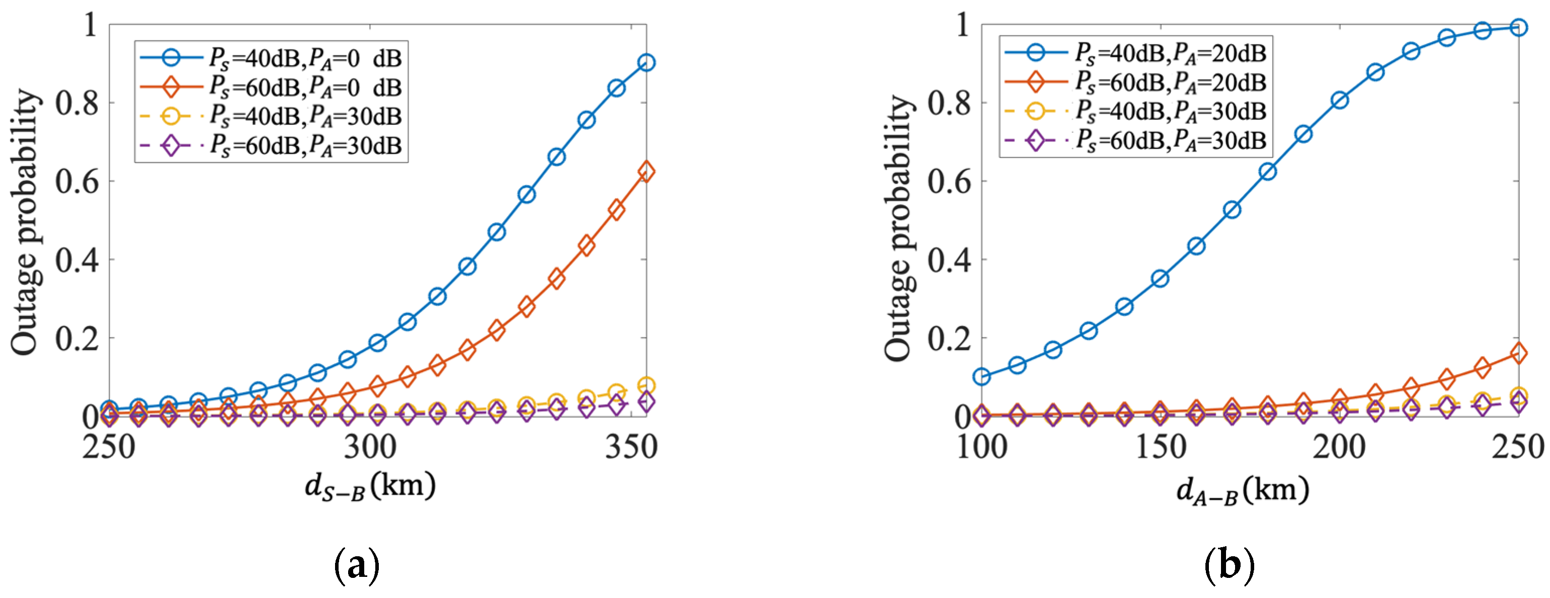
The impact of transmission distance on the outage probability in anti-interference cooperative NOMA systems is opposite to the effect of transmission and forwarding power due to transmission path loss. From the simulation results in Figure 4a, without cooperative forwarding, the farther the transmission distance between broadcast node S and remote node B, the smaller the signal-to-noise ratio (SNR) at the receiving end of node B under enemy interference, leading to a greater outage probability. The outage probability of the system increases significantly after the distance between nodes S and B exceeds 300 km but decreases significantly after node A performs cooperative forwarding for node B because the path loss is higher when the distance exceeds 300 km and the SNR for node B to receive information cannot support normal decoding. Node A is closer to node B than broadcast node S, and the forwarded signal decoded by node A can arrive at the receiving end with a higher SNR, thus lowering the outage probability at the receiving end.
From the simulation results in Figure 4b, when the cooperative forwarding power of node A is 20 dB and the transmission power of broadcast node S is 40 dB, the outage probability of the system increases significantly with the distance between nodes A and B because the condition parameters are at the critical state of the system’s anti-interference performance. Slight deterioration of any condition parameter will have a significant impact on the outage performance of the system. After appropriately increasing the transmission or forwarding power, the influence of the distance between nodes A and B on the outage probability becomes small. Therefore, optimizing the condition parameter status can make the anti-interference cooperative NOMA system for aviation data links more suitable to complex environmental changes.

4.3. Interference Signal Power

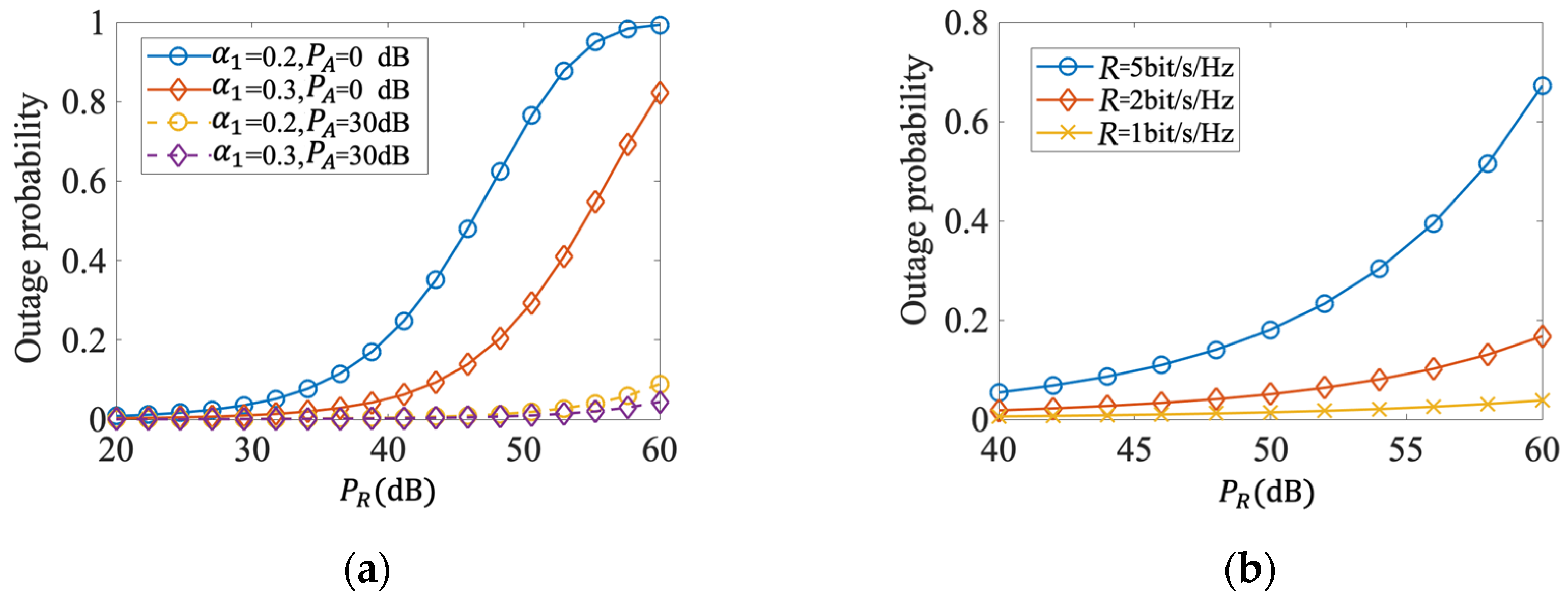
From the simulation results of Figure 5a,b, it can be observed that the higher the interference power of the enemy jamming aircraft, the higher the system outage probability. This is because under fixed receiving condition parameters, the SNR ratio of the remote node is closely related to the strength of the enemy interference, thereby affecting the system’s outage probability. In Figure 5a, when the forwarding power P A is 0 dB, the system’s outage probability quickly increases after the interference power exceeds 40 dB. This is because the SIR at the receiving end deteriorates sharply after breaking through the system’s stable demodulation condition.
However, when node A performs cooperative forwarding with a power of 30 dB, the system’s outage probability is significantly reduced. Even when the interference power reaches 60 dB, the system still maintains a low level of outage probability, thereby improving the system’s anti-interference performance. Therefore, it can be proved that the anti-jamming cooperative NOMA system can enhance the interference tolerance of the aviation data link.
From Figure 5b, it can be seen that the system’s anti-interference ability varies with different rates. When the interference power of the enemy jamming aircraft is high, the outage probability of the system increases with increasing rate. By appropriately reducing the transmission rate, the anti-jamming capability of the data link system can be effectively improved. Therefore, setting the transmission rate at 1 bit/s/Hz is an optimal condition parameter, which can help the system maintain good stability.

4.4. Data Transmission Rate

The simulation results of the impact of signal data rate and transmission/forwarding power on the system outage probability in the anti-jamming cooperative NOMA system of the aviation data link are shown in Figure 6. To ensure low outage probability of the system, higher transmission and forwarding power can achieve higher target rates. Therefore, to maintain a high transmission rate, a higher power must be paid as a cost. When the battlefield environment deteriorates, the system outage performance can be stabilized by reducing the transmission rate.
Through comprehensive analysis of the above, the authors advocate that introducing cooperative NOMA technology into the ADLS-NOMA-I-based aviation data link can significantly improve its anti-jamming capability, thereby providing stronger anti-jamming ability for aircraft formations when facing complex electromagnetic battlefield environments. Therefore, applying cooperative NOMA technology to data link systems not only has important practical significance but also has extensive research value and application prospects.

5. Conclusions

This paper investigates the outage performance of the anti-jamming cooperative NOMA system in aviation data links. A basic theoretical model is established, taking into account enemy interference, and the expression for the system’s outage probability is derived. Through simulation analysis, we found that setting the transmit power of the AWACS, the relay power of the aircraft formation, and the allocation coefficient to 40 dB, 30 dB, and 0.3, respectively, can provide the system with good anti-jamming capability. In addition, we also discussed how to adjust the relevant parameters to maintain system stability in the face of enemy interference and changes in the battlefield environment. This provides an effective reference and basis for the performance evaluation and setting of condition parameters of the data link system.
The results show that introducing cooperative NOMA technology into aviation data link systems can significantly improve their outage performance. Compared to non-cooperative NOMA technology, cooperative NOMA technology not only increases spectral efficiency but also ensures better anti-jamming capability, making it more adaptable to the complex electromagnetic environments of future air battlefields.
As enemy interference necessarily requires reconnaissance, the enemy reconnaissance aircraft can be introduced into the model proposed in this paper for improvement, and the system’s security interruption probability can be explored to optimize and improve it. Furthermore, we can also explore the use of machine learning and artificial intelligence algorithms to detect and mitigate interference in real-time, thereby further enhancing the system’s security and reliability. By continuously monitoring and analyzing the system’s performance, we can continue to optimize and improve the system to meet the evolving demands of modern warfare.

Author Contributions

Conceptualization, N.L.; Methodology, N.L.; Validation, X.Z.; Writing—original draft, X.Z. All authors have read and agreed to the published version of the manuscript.

Funding

This research received no external funding.

Data Availability Statement

Not applicable.

Conflicts of Interest

The authors declare no conflict of interest.

References

  1. Cheng, B.-N.; Wang, X.-H.; Liu, Y.; Liu, F.; Zhang, T.-Y. Design Considerations for Next-Generation Airborne Tactical Networks. IEEE Commun. Mag. 2014, 52, 138–145. [Google Scholar] [CrossRef]
  2. Stoica, A.; Militaru, D.; Moldoveanu, D.; Popa, A. Tactical Data Link—From Link-1 to Link-22. Sci. Bull. Mircea Cel Batran Naval Acad 2016, 19, 346. [Google Scholar]
  3. Sorroche, J.; Byers, R.; Barrett, N. Tactical Digital Information Link-Technical Advice and Lexicon for Enabling Simulation (Tadil-tales) Ii: Link 11/11b. Asrc Communication Ltd Kirtland Afb Nm Distributed Mission Operations Center. Tech. Rep. 200. Available online: https://books.google.com.hk/books/about/Tactical_Digital_Information_Link_Techni.html?id=i19mnQAACAAJ&redir_esc=y (accessed on 1 June 2005).
  4. Yilmaz, A.E.; Ozel, R.M.; Ilk, H.G. Analysis and Modeling of Multiple Tactical Data Links. In Proceedings of the IEEE 12th Signal Processing and Communications Applications Conference, Kusadasi, Turkey, 30 April 2004; pp. 763–766. [Google Scholar] [CrossRef]
  5. Hoekstra, W.E. Tactical Data Links and Interoperability, the Glue between Systems; Nato Consultation Command and Control Agency: Hague, The Netherlands, 2001. [Google Scholar]
  6. Bal, A.; Tajwar, R. Execution of Hybrid NOMA Schemes Concerning Outage Performance and Sum Rate Interplay. Appl. Sci. 2021, 11, 4967. [Google Scholar] [CrossRef]
  7. Reddy, P.V.; Kumar, M.A.; Krishna, G.M. Analytical Review on OMA vs. NOMA and Challenges Implementing NOMA. In Proceedings of the 2nd International Conference on Smart Electronics and Communication (ICOSEC), Trichy, India, 20–22 October 2022; pp. 552–556. [Google Scholar]
  8. Ding, Z.; Lei, X.; Karagiannidis, G.K.; Schober, R.; Yuan, J.; Bhargava, V.K. A Survey on Non-Orthogonal Multiple Access for 5G Networks: Research Challenges and Future Trends. IEEE J. Sel. Areas Commun. 2017, 35, 2181–2195. [Google Scholar] [CrossRef]
  9. Zeng, J.; Zhao, B.; Zhang, Z.; Liu, C.; Hu, R.Q. Investigation on Evolving Single-Carrier NOMA into Multi-Carrier NOMA in 5G. IEEE Access 2018, 6, 48268–48288. [Google Scholar] [CrossRef]
  10. Yadav, A.; Quan, C.; Varshney, P.K.; Poor, H.V. On Performance Comparison of Multi-Antenna HD-NOMA, SCMA, and PD-NOMA Schemes. IEEE Wirel. Commun. Lett. 2021, 10, 715–719. [Google Scholar] [CrossRef]
  11. Maraqa, O.; Rajasekaran, A.S.; Al-Ahmadi, S.; Yanikomeroglu, H.; Sait, S.M. A Survey of Rate-Optimal Power Domain NOMA With Enabling Technologies of Future Wireless Networks. IEEE Commun. Surv. Tutor. 2020, 22, 2192–2235. [Google Scholar] [CrossRef]
  12. Khan, W.U.; Jamshed, M.A.; Lagunas, E.; Chatzinotas, S.; Li, X.; Ottersten, B. Energy Efficiency Optimization for Backscatter Enhanced NOMA Cooperative V2X Communications under Imperfect CSI. IEEE Trans. Intell. Transp. Syst. 2022, 1–12. [Google Scholar] [CrossRef]
  13. Alkama, D.; Zenadji, S.; Ouamri, M.A.; Khireddine, A.; Azni, M. Performance of Resource Allocation for Downlink Non-Orthogonal Multiple Access Systems in Tri-Sectorial Cell. In Proceedings of the 2022 IEEE International Conference on Electrical Sciences and Technologies in Maghreb (CISTEM), Tunis, Tunisia, 26–29 October 2022; pp. 1–6. [Google Scholar] [CrossRef]
  14. Prashar, A.; Sood, N. Performance Analysis of MIMO-NOMA and SISO-NOMA in Downlink Communication Systems. In Proceedings of the 2nd International Conference on Intelligent Technologies (CONIT), Hubli, India, 24–26 June 2022; pp. 1–5. [Google Scholar] [CrossRef]
  15. Kaur, J.; Singh, M.L. User Assisted Cooperative Relaying in Beamspace Massive MIMO NOMA Based Systems for Millimeter Wave Communications. China Commun. 2019, 16, 103–113. [Google Scholar] [CrossRef]
  16. Auyo, A.M.; Babale, S.A.; Bello, L.M. Effect of Inspired CR-NOMA Power Allocation on Bit Error Rate for Three User NOMA System. In Proceedings of the 2022 IEEE Nigeria 4th International Conference on Disruptive Technologies for Sustainable Development (NIGERCON), Lagos, Nigeria, 5–7 April 2022; pp. 1–5. [Google Scholar] [CrossRef]
  17. Durceylan, M.N.; Gemici, Ö.F.; Özdemir, G.; Hökelek, İ.; Çırpan, H.A. Fuzzy Logic Based Power Allocation for Cooperative NOMA Systems. In Proceedings of the 2022 International Balkan Conference on Communications and Networking (BalkanCom), Sarajevo, Bosnia and Herzegovina, 22–24 August 2022; pp. 11–15. [Google Scholar] [CrossRef]
  18. Iswarya, N.; Jayashree, L.S. A Survey on Successive Interference Cancellation Schemes in Non-Orthogonal Multiple Access for Future Radio Access. Wirel. Pers. Commun. 2021, 120, 1057–1078. [Google Scholar] [CrossRef]
  19. Ding, Z.; Yang, Z.; Fan, P.; Poor, H.V. On the Performance of Non-Orthogonal Multiple Access in 5G Systems with Randomly Deployed Users. IEEE Signal Process. Lett. 2014, 21, 1501–1505. [Google Scholar] [CrossRef]
  20. Gupta, P.; Ghosh, D. User Fairness based Energy Efficient Power Allocation for Downlink Cellular NOMA System. In Proceedings of the 2020 5th International Conference on Computing, Communication and Security (ICCCS), Patna, India, 14–16 October 2020; pp. 1–5. [Google Scholar]
  21. Chen, J.; Yang, L.; Alouini, M.-S. Physical Layer Security for Cooperative NOMA Systems. IEEE Trans. Veh. Technol. 2018, 67, 4645–4649. [Google Scholar] [CrossRef]
  22. Bal, A.; Khan, M.R.H.; Peyal, M.K. Performance Comparison among Hybrid NOMA Schemes Focusing on Outage Performance and Sum Rate Arrangement. In Proceedings of the 2021 2nd International Conference for Emerging Technology (INCET), Belagavi, India, 21–23 May 2021; pp. 1–5. [Google Scholar] [CrossRef]
  23. Ding, Z.; Peng, M.; Poor, H.V. Cooperative Non-Orthogonal Multiple Access in 5G Systems. IEEE Commun. Lett. 2015, 19, 1462–1465. [Google Scholar] [CrossRef]
  24. Guo, S.; Xiaolin, X.; Bao, T.; Yuguang, F. Research Progress of Anti-jamming Technology of Unmanned Aerial Vehicle (UAV) Data Link. IOP Conf. Ser. Mater. Sci. Eng. 2020, 816, 012011. [Google Scholar] [CrossRef]
  25. Li, C.; Qi, P.; Wang, D.; Li, Z. On the Anti-Interference Tolerance of Cognitive Frequency Hopping Communication Systems. IEEE Trans. Reliab. 2020, 69, 1453–1464. [Google Scholar] [CrossRef]
  26. Suryana, J.; Candra, D. Implementation of Link-16 based Tactical Data Link System Using Software-Defined Radio. In Proceedings of the 2019 International Conference on Electrical Engineering and Informatics (ICEEI), Bandung, Indonesia, 9–10 July 2019; pp. 555–559. [Google Scholar]
  27. Qi, N.; Zhang, Q.; Liu, R.P.; Huang, J.; Leung, V.C.M. A Learning-Based Spectrum Access Stackelberg Game: Friendly Jammer-Assisted Communication Confrontation. IEEE Trans. Veh. Technol. 2021, 70, 700–713. [Google Scholar] [CrossRef]
  28. Yu, F.; Na, L.; Kun, C. Performance Analysis of Data Link System Based on NOMA Technology under Interference Conditions. J. Signal Process. 2020, 36, 1029–1037. [Google Scholar]
  29. Elsaraf, Z.; Ahmed, A.; Khan, F.A.; Ahmed, Q.Z. Non-orthogonal multiple access for wireless communication networks by exploiting the EXIT chart analysis. EURASIP J. Wirel. Commun. Netw. 2021, 2021, 79. [Google Scholar] [CrossRef]
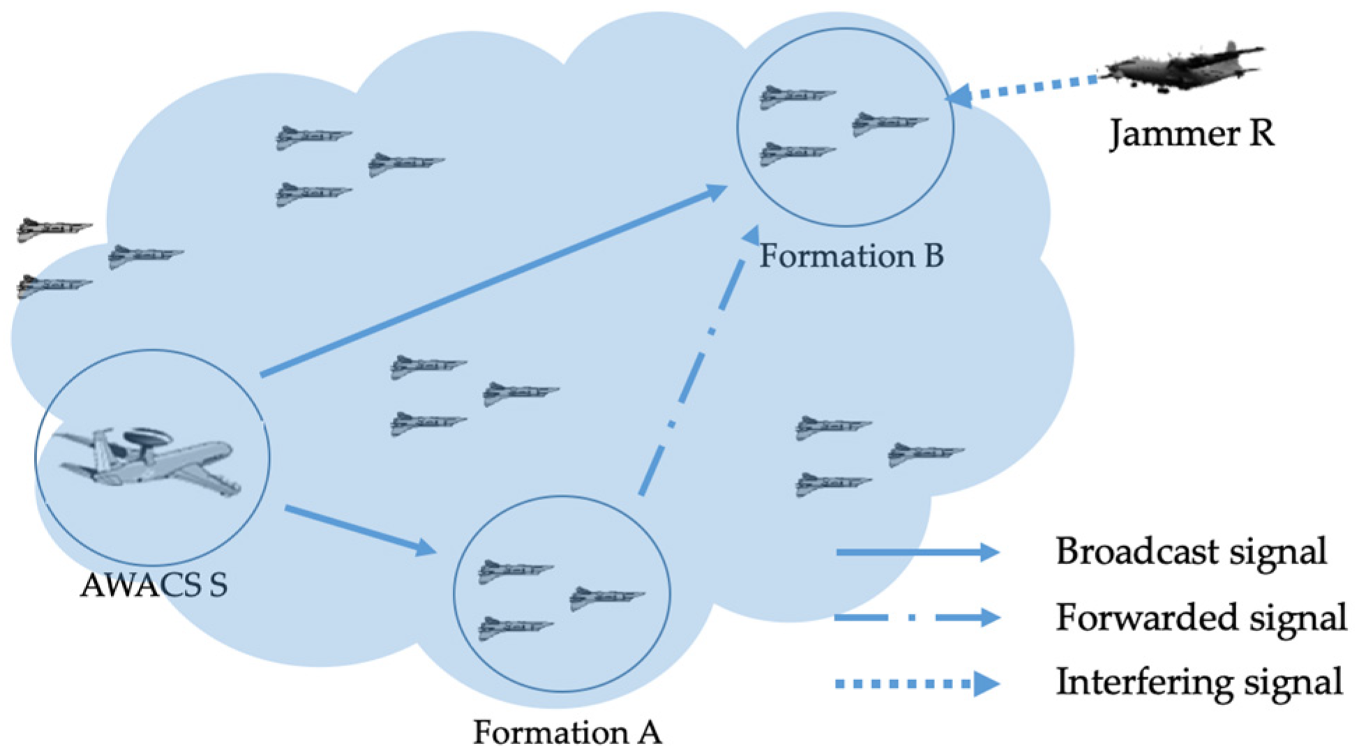
Figure 1. Schematic diagram of carrying out a combat mission.
Electronics 12 02182 g001
Figure 2. Model of anti-interference cooperative NOMA system for aviation data link.
Electronics 12 02182 g002
Figure 3. The outage probability varies with transmission power at different power distribution coefficients and transmission power: (a) the outage probability varies with transmit signal power; (b) the outage probability varies with relay signal power.
Electronics 12 02182 g003
Figure 4. The outage probability varies with transmission distance at different transmission power: (a) the outage probability varies with transmission distance from S to B; (b) the outage probability varies with transmission distance from A to B.
Electronics 12 02182 g004
Figure 5. The outage probability varies with interference signal power: (a) the outage probability varies at different power distribution coefficients and transmission power; (b) the outage probability varies at different transfer rates.
Electronics 12 02182 g005
Figure 6. The outage probability varies with the data transmission rate at different transmission power.
Electronics 12 02182 g006
Table 1. Simulation parameters.
ParametersValue
Transmit power of the AWACS P s 40 dB
Relay power of aircraft formation A  P A 30 dB
Enemy jamming power P R 50 dB
Power allocation coefficient α 1 0.3
Transmission distance d S A 200 km
Transmission distance d S B 300 km
Transmission distance d A B 250 km
Transmission distance d R B 200 km
Rice factor k S A 10 dB
Rice factor k S B 15 dB
Rice factor k A B 12.5 dB
Rice factor k R B 10 dB
Data transmission rate R1 bit/s
Disclaimer/Publisher’s Note: The statements, opinions and data contained in all publications are solely those of the individual author(s) and contributor(s) and not of MDPI and/or the editor(s). MDPI and/or the editor(s) disclaim responsibility for any injury to people or property resulting from any ideas, methods, instructions or products referred to in the content.