1. Introduction
Internet of Things (IoT) technologies have received a significant boost in development recently. In 2022, the market capitalization of the Internet of Things amounted to USD 201 billion. Experts predict that by 2023 this capitalization should reach USD 238 billion [
1]. The growing incomes of the population and the improvement of the quality of life contribute to the increasing penetration of electronic devices into everyday life. In addition, factors such as environmental monitoring, the lockdown caused by the COVID-19 pandemic, the development of cloud services and artificial intelligence have greatly contributed to the development of the IoT.
At the moment, most IoT devices use wireless communication to transmit information and run on batteries. The use of IoT devices can be difficult in urban environments, where the frequency spectrum can be significantly congested. In addition, applications such as monitoring and automation of industrial processes require that data from sensors be transmitted over a long distance in an unfavorable wireless environment due to the architecture of enterprises (reinforced concrete structures). The number of IoT devices is growing every year. This is giving a boost to the development of Power Line Communications (PLC) technology. The term PLC refers to the use of a power supply circuit to transmit data. There are currently many different standards for data transmission over power circuits, the best known of which are: G3-PLC, PRIME, X-10 and Homeplug [
2,
3,
4,
5]. The use of PLCs eliminates the need for an additional communication line, which reduces costs.
The use of data transmission technology over power circuits is fraught with problems, namely:
A limited frequency range (typically 0.1–50 MHz), as the signal attenuation increases at higher frequencies;
A complex interference environment, which further reduces the already limited available frequency range.
The technology of full-duplex data transmission over power circuits is one of the most effective technologies that can increase spectral efficiency up to two times. This was shown by the analysis of technologies for increasing the spectral efficiency of data transmission systems over power supply circuits. A half-duplex communication system is a system where information is received and transmitted without time and frequency separation. The difficulty in using a full duplex is the need to suppress its own transmitter signal (interference signal). Analog and digital cancellation is used for this purpose. The literature [
6,
7] discusses analog cancellation of the interference signal in a full-duplex communication system over power circuits. Thus, the authors of [
6] used a circulator with variable impedance as an analog cancellation device, while the authors [
7] used an analog filter. In both works, the analog part was controlled using the Least Mean Squares (LMS) algorithm. This was performed to adjust the changing conditions in the channel. Another work dedicated to the topic of analog echo cancellation in full-duplex power-line systems using adaptive filters is [
8]. A significant part of the work on digital cancellation of the interference signal in a full-duplex communication system relates to wireless communication. Thus, the literature [
9,
10] discusses digital cancellation of the interference signal in a full-duplex system. The authors used a digital filter where the filter coefficients were calculated periodically, using a preamble. The authors [
11,
12] also used a digital filter, but the coefficients were adjusted using the adaptive Recursive Least Squares (RLS) algorithm. The literature [
13] stands out among other works on digital cancellation over power lines. The authors of this paper use a modification of the adaptive LMS filtering algorithm when performing digital cancellation of the interference signal to improve filter performance in a fast-changing channel.
Adaptive algorithms are common algorithms for digital cancellation or algorithms to control analog cancellation, as can be seen from the above works. By adaptive filters is meant linear filters that use an adaptive algorithm to calculate weight coefficients.
Under PLC channel conditions, the operation of the adaptive filter is complicated by the presence of many additional disturbances and a constantly changing channel. This can have a significant impact on the rate of convergence of the filter coefficients and the quality of filtration. The PLC channel has both additive and multiplicative interferences, and their impact leads to significant distortion of the transmitted signal. In the PLC channel, interferences are divided into two types: pulsed and periodic. The main source of interference is most electrical appliances connected to the mains. The level of interference in the channel varies depending on the phase of the voltage in the power grid. This type of interference is called cyclostationary. As already mentioned, such an unfavorable situation significantly complicates the process of evaluating and cancelling for the interference signal. This paper considers digital cancellation using adaptive filtering under the influence of variable voltage in the power grid. A modification of the RLS algorithm was proposed to improve the quality of the functioning of the adaptive filter in the presence of interference in the PLC channel.
The main contribution of this work is the proposed solution, which includes modifications to the RLS algorithm to address the long-standing problem of digital echo cancellation in PLC channels. Extensive experiments were conducted to validate the effectiveness of the proposed solution compared to other approaches. The results clearly demonstrate the superiority of the proposed solution, indicating its potential to have a significant impact on the research field.
The paper presents an overview of some existing algorithms for digital cancellation of the signal of its own transmitter in the conditions of a PLC channel. The first algorithm is RLS [
14,
15] and the second is particle swarm optimization (PSO) [
16]. These algorithms were chosen due to the fact that they are often found in papers devoted to the full-duplex topic [
11,
12,
17]. The RLS algorithm related to the family of the algorithms that minimize least squares error, such as LMS, normalized least mean squares (NLMS) and LMS also used in full duplex [
13]. The RLS has the fastest convergence among other least squares algorithms, is not sensitive to the energy of the input signal like LMS and does not require choosing the optimal learning rate, as is required by LMS and NLMS algorithms [
14,
15]. These reasons led to the use of RLS and PSO algorithms in this work.
A modification of the RLS algorithm has been proposed to improve the level of cancellation. During the simulation, the efficiency of the RLS algorithm for the echo cancellation problem was investigated, and then the optimal number of filter coefficients was determined. The following characteristics were obtained: the dependence of the signal-to-interference ratio (SIR) at the filter output on the SIR at the filter input, the dependence of the change in the power of the useful signal, and the interference signal after filtering with a different value of SIR at the filter input.
During the experiment, 100 samples of signals were measured with the presence of periodic interference from switching power supplies. Digital cancellation of the interference signal was carried out using the echo cancellation methods discussed above. Such characteristics as error vector magnitude (EVM) and SIR were captured. The results were averaged and recorded in a table.
2. Description of Adaptive Algorithms
In this article, a full-duplex data transmission is carried out in the power supply circuit. We consider only digital cancellation, for which an adaptive filter is used. Some approaches to using adaptive filters for echo cancellation are described in [
14,
15,
17]. A schematic diagram of an adaptive filter operating in echo cancellation mode is shown in
Figure 1.
The reference signal is the signal to be received at the filter output. The input signal is the signal processed by the filter. The output signal is a reference signal processed by the filter. The error signal is the difference between the output signal and the reference signal. The received signal is used as the reference signal. This is the sum of a known interfering signal and an unknown useful signal.
The received signal in full-duplex transmission mode is described by the expression (1) [
14,
15].
where
and
is a transfer characteristic channel,
is a useful signal,
is a signal interference,
represents the presence of white Gaussian noise that is added to the signal.
The input signal of the filter is a known interference signal
. The output signal of the adaptive filter is described by the expression:
where
is a vector of filter weight coefficients,
is a number of filter coefficients.
The adaptive filter error signal is described as:
If the filter operates in echo cancellation mode, the useful signal is the error signal and not the output signal. Below the expression (4) is described in more detail.
where
is an evaluation of the interference signal channel,
is an error setting the filter coefficients.
Next, we will look at the algorithms used to perform adaptive filtering.
Algorithms 1.
Particle swarm optimization. PSO is a stochastic optimization method based on simulated social behavior. The search for an optimal solution is performed by several interacting particles in a given search space. The mathematical description of the canonical PSO method, which we used in the simulation, is presented in [
16,
17].
The available set of particles (swarm of particles) in n-dimensional space is denoted as [
16]:
where
is the particle coordinates,
is the number of particles in the swarm,
is the number of search spaces.
In this paper, PSO is used to find the optimal vector of weight coefficients. Therefore, the number of search spaces will be equal to the length of the vector of weighting coefficients. Thus, the coordinates of each particle in n-dimensional space are defined by the vector [
16]:
The mean square function was chosen as the error function for which the solution search is performed by the PSO method [
16]:
where
is the mathematical expectation.
At the moment, a large number of varieties of the PSO algorithm exist [
14]. In this paper, the canonical FDM algorithm was used. At each iteration, the new particle coordinate is defined as [
16]:
where
is the acceleration of the m-th particle,
is the restriction coefficient,
are the particle acceleration restriction coefficients,
is the random uniform distribution function,
is the element-by-element multiplication,
is the best position of the
m-th particle,
is the best position of the
m-th particle among two neighboring ones.
There are currently a large number of algorithms based on PSO. The PSO algorithm finds application in the problem of interference signal cancellation, although it is used in optimization problems [
16]. In such a problem, high computational complexity and the selection of a large number of hyperparameters are the main challenges of using PSO. Simplicity of implementation and resistance to local minima can be attributed to the advantage of the method.
Algorithms 2.
Recursive Least Squares. Recursive Least Squares (RLS) is an adaptive algorithm used to estimate the coefficients of a linear system. It is often used for signal processing applications, such as echo cancellation and equalization. The algorithm updates the estimates of the coefficients in a recursive manner, using the most recent input and output data, and a forgetting factor that controls the influence of past data on the current estimate. The RLS algorithm is known for its fast convergence and robustness to measurement noise, making it a popular choice for real-time applications. The mathematical description of the RLS method, which we used in the simulation, is presented in [
14]. This algorithm is based on minimizing the weighted least squares error:
where
is the number of signal samples,
is the current count,
is an exponential weighting factor used in the filtering problem, typically taking a value between 0.99 and 1, which is commonly referred to as the forgetting factor [
14].
The error signal is calculated as:
where
is the
k-th count of the reference signal with the number,
is the hermitian-conjugate
k-th vector of weighting coefficients of a filter of length N,
is the
k-th vector of the input signal of length N.
In this algorithm, the solution of the Wiener filtering problem is based on the search for recurrent relations of the autocorrelation of the input signal and the cross-correlation of the input signal with the reference [
14]:
where
is the vector cross-correlation of input and reference signal,
is the matrix autocorrelation of an input signal of size N by N,
is the input signal vector.
The initial value of the inverse autocorrelation matrix is calculated as [
14]:
where
is the input signal variance.
Thus, by calculating the above ratios, the RLS algorithm can be represented as [
14]:
where
is the vector of the Kalman coefficient.
The algorithm consists of four steps. The first step is to calculate the Kalman coefficients, which is done using Equation (16). The next step is to calculate the inverse autocorrelation matrix using Equation (17). After that, in step three, the error correction signal is computed using Equation (18). Finally, in step four, the filter coefficients are calculated using Equation (19). This algorithm is used in the RLS algorithm to minimize the error between the filter output and the desired signal.
Currently, in addition to the RLS algorithm, algorithms such as Least Means Squares (LMS) and Normalized Least Means Squares (NLMS) are used in adaptive filtering problems [
14,
15]. LMS is used in the applications where it is possible to determine the permissible value of the convergence step, which ensures the stability of the algorithm and the optimal convergence rate, which itself requires a priori information about the statistical characteristics of the input signal. If the characteristics of the input signal change over time, the NLMS algorithm is used.
In the NLMS algorithm, the convergence step is adapted during the filtering process. However, the need to select a dynamic convergence step, on which the speed of convergence is dependent, is still present. The NLMS algorithm is more stable when processing non-stationary signals than LMS, due to gradient normalization.
RLS provides the fastest convergence rate and lowest steady-state residual error compared to the algorithms described above. In addition, RLS does not require the selection of a hyperparameter such as the convergence step of the algorithm, due to which it is used in full-duplex communication systems [
11].
When adaptive filters are used as echo cancellers, the output signal of the filter is an error signal. Therefore, interference must be suppressed, and the useful signal must be preserved. One of the filter parameters is the weight parameter forgetting factor. This parameter determines the effect of the previous filter coefficients on the calculation of new ones. The smaller it is, the weaker is this influence. If the value of this parameter is small, the filter can suppress not only the interference signal, but also the useful signal, due to overtraining. Furthermore, the stability of the filter may be disrupted. The value of the forgetting factor equal to 1 was used in the work for the above reasons.
Algorithms 3.
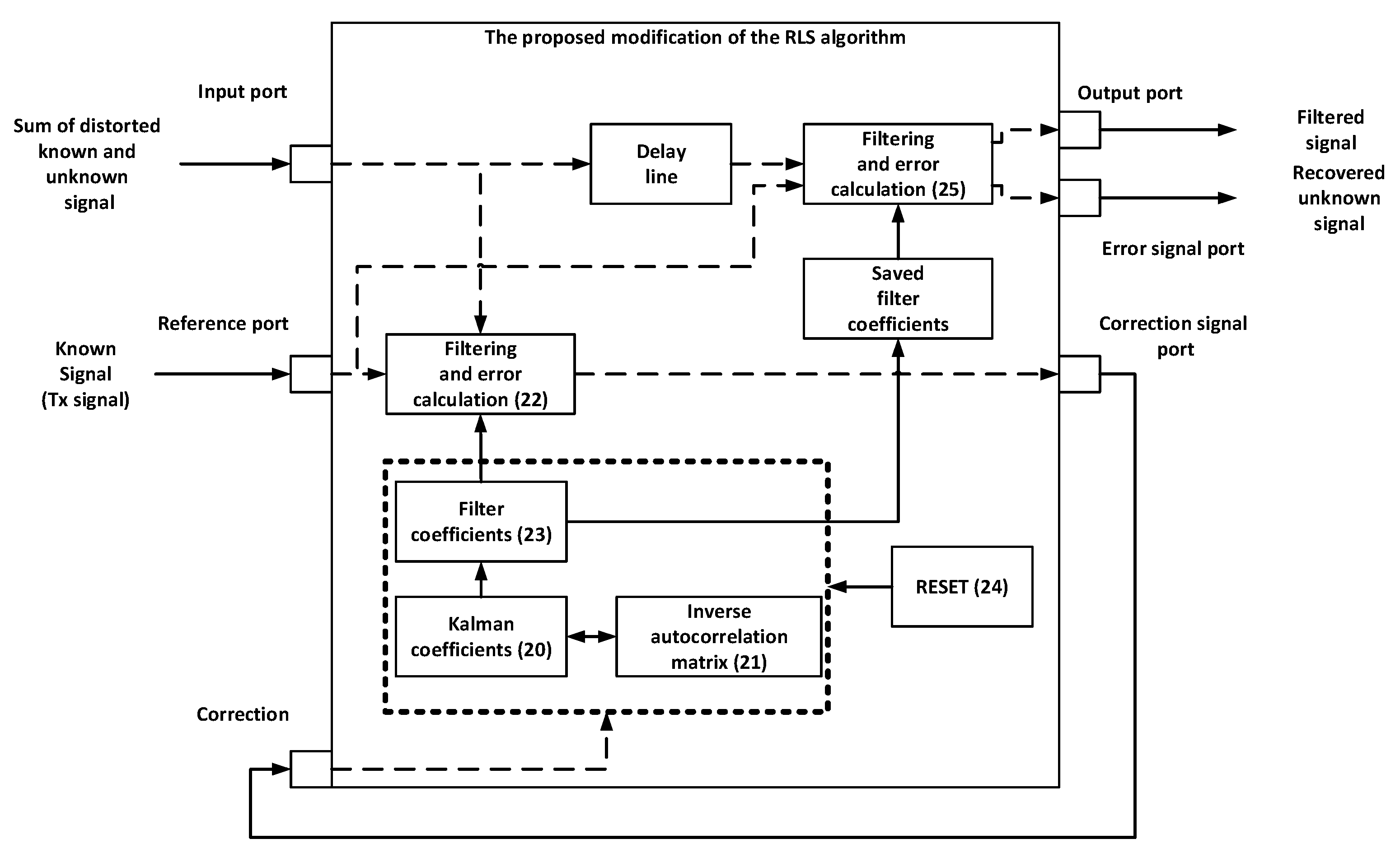
Modified Recursive Least Squares. A modification of the classical RLS algorithm was used to improve the quality of the adaptive filter in the power line channel. The main change is that the filter weights are calculated over a period of time
. In our case, the duration of one OFDM symbol was taken as time T1. After that, the calculated value is written to the register. The original vector of the weighting coefficients, the inverse correlation matrix and the vector of the Kalman coefficients are reinitialized. During the next period of time
, the calculation of the weighting coefficients continues, while the filtering of the signal is carried out using the coefficients stored in the register. This procedure is repeated throughout the filtration process. The functional diagram of the algorithm is shown in
Figure 2. Function blocks in
Figure 2 contain references on the equation related to the operation performed in the block.
The mathematical description of the algorithm is presented below.
where
is the variable counter,
is the time period during which the coefficients are calculated,
is the calculated vector of weight coefficients, which is stored in memory,
is filter output signal.
The following text provides a detailed description of the mathematical formulas used in the model. The filter coefficients are initially initialized to zero values. First, the Kalman coefficients are calculated in Equation (20). Then, Equation (21) is used to calculate the inverse autocorrelation matrix. The error correction signal is generated using Equation (22). The filter coefficients are calculated using Equation (23). The calculated filter coefficients are saved in the memory and all filter parameters are reset after a given time period using Equation (24). Finally, Equation (25) is used to filter the signal with the saved coefficients and subtract the filtered signal from the input signal to obtain the payload signal.
The use of precalculated coefficients together with periodic reinitialization of the filter avoids the influence of significant changes in the input signal on the further process of filter adaptation. The calculation period of the coefficients can be quite small due to the fast convergence of the RLS algorithm. In addition, the changes in signal amplitudes, as well as the noise, lead to fluctuations in the filter coefficients in the classical implementation. The modified algorithm reduces the number of fluctuations considerably.
A similar approach has been demonstrated in [
13], where the authors propose to reset the filter coefficients or change their sign in case of sudden channel changes.
If sudden changes occur in the channel, there is no guarantee that the inversion of the sign will bring the current filter coefficients closer to optimal. Furthermore, a reset requires some time to adapt the filter to new conditions. In addition, the disruption of the filter is not always associated with sudden changes in the channel; this will be demonstrated in the future. Slow changes also lead to a deterioration in the quality of filtration, since previously calculated filter coefficients can have a negative impact on the adaptation process. Therefore, such drastic measures as sign inversion or reset will not be appropriate.
4. Conclusions
For this article, echo signal cancellation was performed in the conditions of the power supply circuit channel, taking into account the influence of the alternating voltage of the power grid. Three adaptive filtering algorithms—RLS, PSO, and modified RLS—were used for cancelling an echo signal and separating an unknown useful signal.
RLS and PSO algorithms show worse results compared to the proposed method. The cancellation level for the proposed method is 4 dB higher compared to PSO, and 2 dB higher compared to RLS. It is worth noting that PSO, unlike RLS, has greater computational complexity. The proposed modified RLS provides computational complexity comparable to RLS, and signal interference suppression is the highest compared to RLS and PSO. The proposed modification of RLS can be used in communication systems that experience periodic channel interference, such as power lines.
According to our experiments, the PSO algorithm has the largest computational complexity, as it involves a set of filter coefficient registers that are updated on every iteration. This makes it slowest, and it consumes more resources compared to other algorithms. The RLS algorithm, on the other hand, has a computational complexity of O(N2), where N is the number of filter coefficients. It utilizes only one register for the filter coefficients, making it faster than the PSO algorithm. In our experiments, the RLS algorithm was the fastest.
In comparison to the RLS algorithm, the proposed modified RLS algorithm requires an additional delay line, a register to store calculated filter coefficients, a resetting block and a convolutional block. However, its computational complexity is insignificantly higher than the RLS algorithm and does not require many resources.
It is evident that in order for a full-duplex power-line data transmission system to function, both digital and analog echo cancellation must be utilized. This will prevent overload of the dynamic range of the receiving circuit by the transmitter signal that penetrates into it. At present, we are developing a hardware implementation of analog echo cancellation, in which we are addressing several tasks. The first task involves digital-to-analog echo cancellation, which includes the formation of a compensation signal in digital form, its subsequent conversion to an analog signal through a digital-to-analog converter and compensation of the transmitter signal in a summation circuit. The second task is to implement an electronic circulator in the 1–20 MHz range, which allows reducing the power of the transmitter signal that penetrates into the receiving circuit. The last task is to match the output impedance of the circuit with the power network and adapt it to possible changes. In the future, we plan to combine the proposed and used solutions and implement a full prototype of a full-duplex power-line data transmission system, which will enable the evaluation of the effectiveness of using full-duplex technology in such systems.

 ,
, 


