

Current-Mode First-Order Versatile Filter Using Translinear Current Conveyors with Controlled Current Gain

 ,
, 

 and
and
Abstract
:1. Introduction
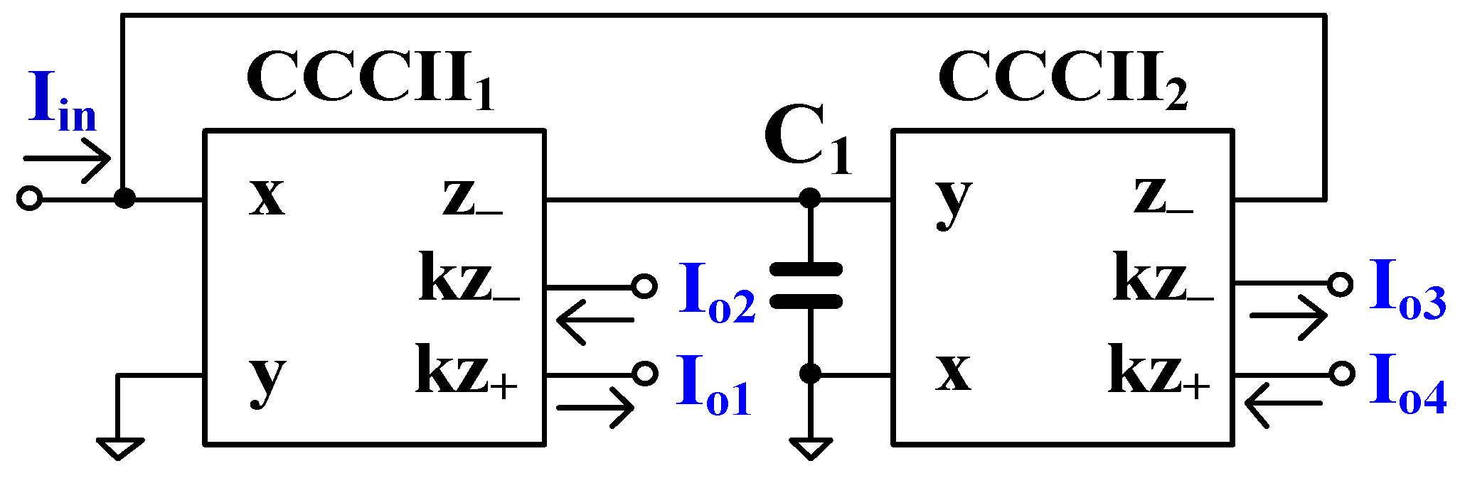
2. Circuit Description
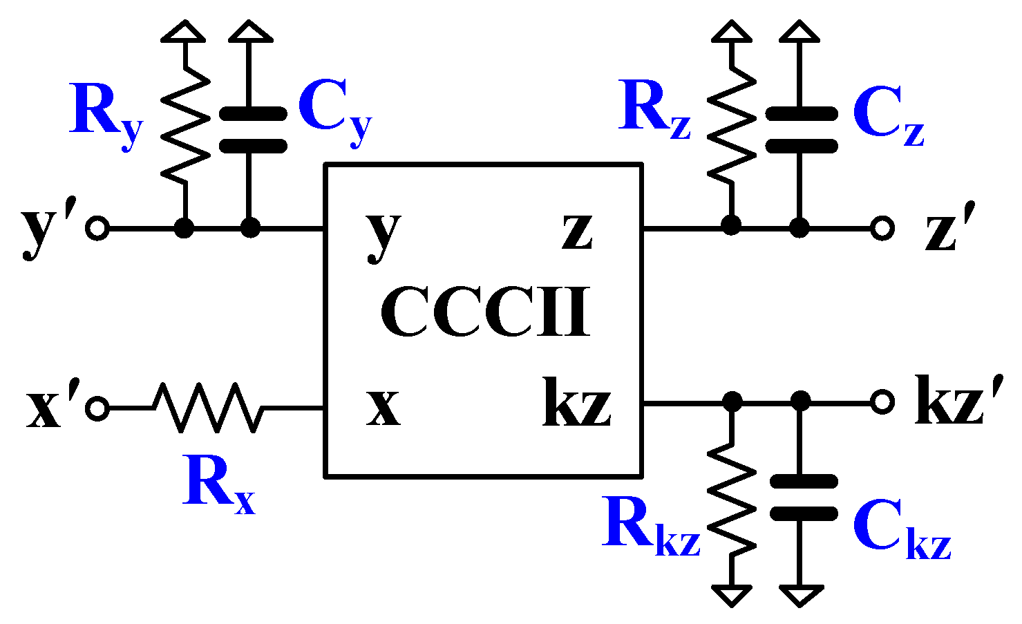
3. Non-Ideality Analysis
4. Application to Quadrature Oscillator
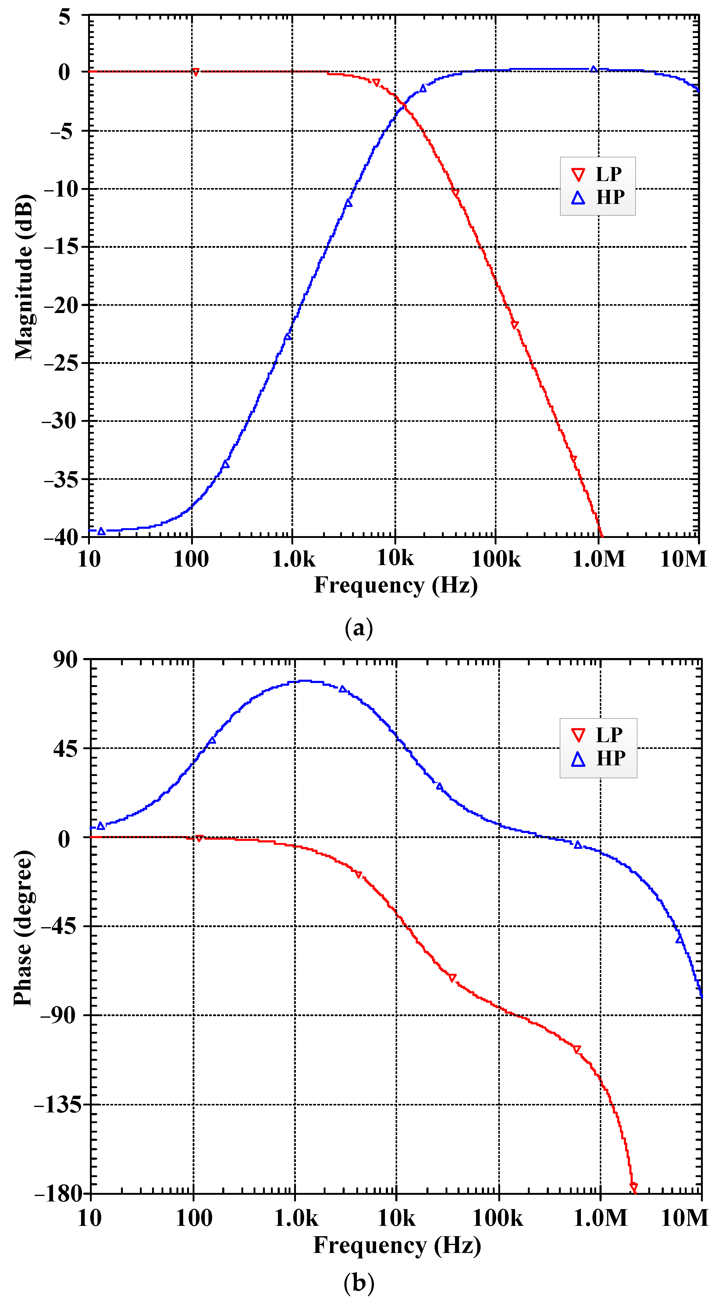
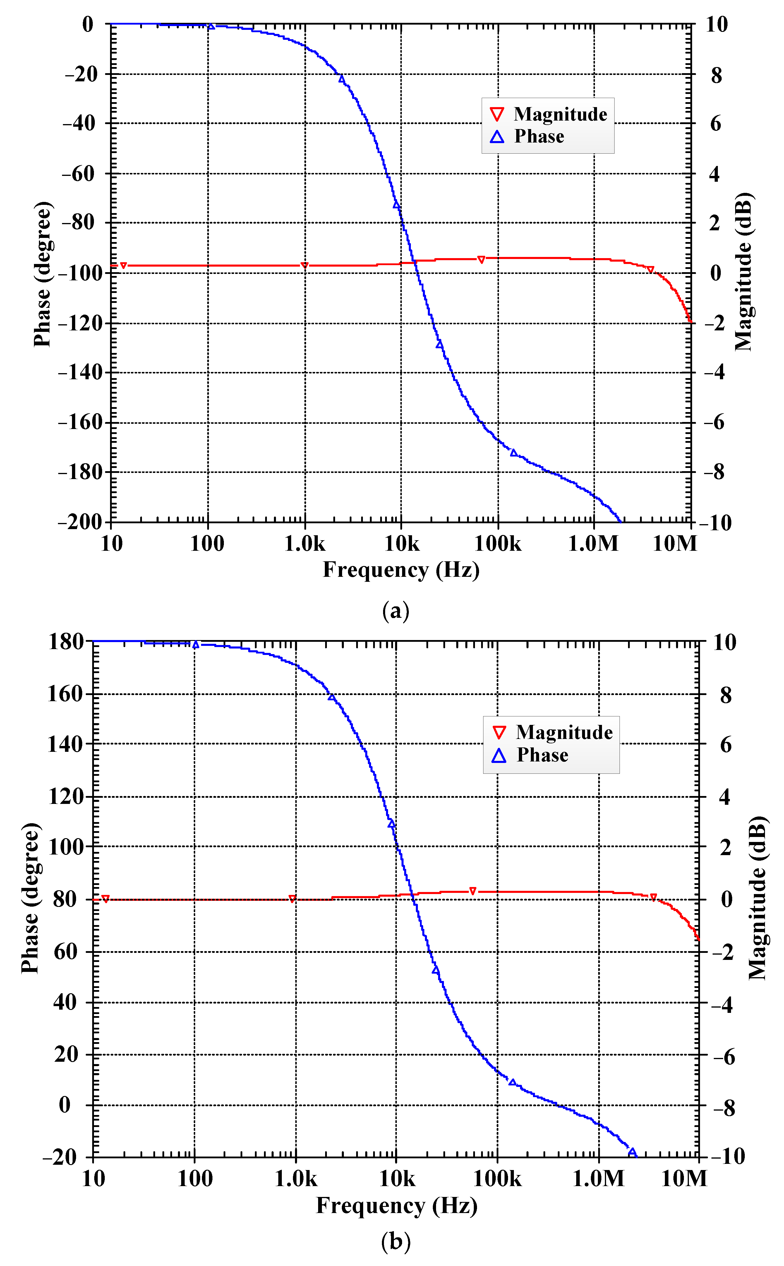
5. Simulation Results
6. Conclusions
Author Contributions
Funding
Data Availability Statement
Conflicts of Interest
References
- Roberts, G.; Sedra, A. All current-mode frequency selective circuits. Electron. Lett. 1989, 25, 759–761. [Google Scholar] [CrossRef]
- Toumazou, C.; Lidgey, F.J.; Haig, D.G. Analogue IC Design: The Current-Mode Approach; Peter Peregrinus: London, UK, 1990. [Google Scholar]
- Toker, A.; Ozoguz, S.; Cicekoglu, O.; Acar, C. Current-mode all-pass filters using current differencing buffered amplifier and a new high-Q bandpass filter configuration. IEEE Trans. Circuits Syst. II Analog. Digit. Signal Process. 2000, 47, 949–954. [Google Scholar] [CrossRef] [PubMed]
- Gift, S.J.G. The application of all-pass filters in the design of multiphase sinusoidal systems. Microelectron. J. 2000, 31, 9–13. [Google Scholar] [CrossRef]
- Idros, M.F.B.M.; Abu Hassan, S.F.B. A design of butterworth low pass filter’s layout basideal filter approximation on the ideal filter approximation. In Proceedings of the 2009 IEEE Symposium on Industrial Electronics & Applications, Kuala Lumpur, Malaysia, 4–6 October 2009; pp. 754–757. [Google Scholar] [CrossRef]
- Kumari, S.; Nand, D. DDCC-based MISO type voltage-mode first-order universal filter. In Proceedings of the 2022 2nd International Conference on Intelligent Technologies (CONIT), Hubli, India, 24–26 June 2022; pp. 1–6. [Google Scholar] [CrossRef]
- Dogan, M.; Yuce, E. A first-order universal filter including a grounded capacitor and two CFOAs. Analog. Integr. Circuits Signal Process. 2022, 112, 379–390. [Google Scholar] [CrossRef]
- Singh, P.; Varshney, V.; Kumar, A.; Nagaria, R. Electronically tun-able first order universal filter based on CCDDCCTA. In Proceedings of the 2019 IEEE Conference on Information and Communication Technology, Allahabad, India, 6–8 December 2019; pp. 1–6. [Google Scholar] [CrossRef]
- Jaikla, W.; Talabthong, P.; Siripongdee, S.; Supavarasuwat, P.; Suwanjan, P.; Chaichana, A. Electronically controlled voltage mode first order multifunction filter using low-voltage low-power bulk-driven OTAs. Microelectron. J. 2019, 91, 22–35. [Google Scholar] [CrossRef]
- Jaikla, W.; Buakhong, U.; Siripongdee, S.; Khateb, F.; Sotner, R.; Silapan, P.; Suwanjan, P.; Chaichana, A. Single Commercially Available IC-Based Electronically Controllable Voltage-Mode First-Order Multifunction Filter with Complete Standard Functions and Low Output Impedance. Sensors 2021, 21, 7376. [Google Scholar] [CrossRef]
- Barile, G.; Safari, L.; Pantoli, L.; Stornelli, V.; Ferri, G. Electronically Tunable First Order AP/LP and LP/HP Filter Topologies Using Electronically Controllable Second Generation Voltage Conveyor (CVCII). Electronics 2021, 10, 822. [Google Scholar] [CrossRef]
- Duangmalai, D.; Suwanjan, P. The voltage-mode first order universal filter using single voltage differencing differential input buffered amplifier with electronic controllability. Int. J. Electr. Comput. Eng. IJECE 2022, 12, 1308–1323. [Google Scholar] [CrossRef]
- Singh, P.; Nagaria, R.K. Voltage mode and trans-admittance mode first-order universal filters employing DV-EXCCCII. Aust. J. Electr. Electron. Eng. 2022, 19, 396–406. [Google Scholar] [CrossRef]
- Dogan, M.; Yuce, E.; Dicle, Z. CFOA-based first-order voltage-mode universal filters. AEU Int. J. Electron. Commun. 2023, 161. [Google Scholar] [CrossRef]
- Li, Y.-A. A series of new circuits based on CFTAs. AEU Int. J. Electron. Commun. 2012, 66, 587–592. [Google Scholar] [CrossRef]
- Herencsar, N.; Lahiri, A.; Koton, J.; Vrba, K. First-order multifunction filter design using current amplifiers. In Proceedings of the 2016 39th International Conference on Telecommunications and Signal Processing (TSP), Vienna, Austria, 27–29 June 2016; pp. 279–282. [Google Scholar] [CrossRef]
- Kumar, A.; Paul, S.K. Current mode first order universal filter and multiphase sinusoidal oscillator. AEU Int. J. Electron. Commun. 2017, 81, 37–49. [Google Scholar] [CrossRef]
- Chaturvedi, B.; Mohan, J.; Jitender; Kumar, A. A novel realization of current-mode first order universal filter. In Proceedings of the 2019 6th International Conference on Signal Processing and Integrated Networks (SPIN), Noida, India, 7–8 March 2019; pp. 623–627. [Google Scholar] [CrossRef]
- Horng, J.-W.; Wu, C.-M.; Zheng, J.-H.; Li, S.-Y. Current-mode first-order highpass, lowpass, and allpass filters using two ICCIIs. In Proceedings of the 2020 IEEE International Conference on Consumer Electronics-Taiwan (IC-CE-Taiwan), Taoyuan, Taiwan, 28–30 September 2020; pp. 1–2. [Google Scholar] [CrossRef]
- Yucel, F. A DVCC-Based Current-Mode First-Order Universal Filter. J. Circuits Syst. Comput. 2021, 30, 2150305. [Google Scholar] [CrossRef]
- Yuce, E.; Minaei, S. A new first-order universal filter consisting of two ICCII + s and a grounded capacitor. AEU Int. J. Electron. Commun. 2021, 137, 153802. [Google Scholar] [CrossRef]
- Raj, A.; Bhaskar, D.R.; Senani, R.; Kumar, P. Extension of recently proposed two-CFOA-GC all pass filters to the realisation of first order universal active filters. AEU Int. J. Electron. Commun. 2022, 146, 154119. [Google Scholar] [CrossRef]
- Herencsar, N.; Koton, J.; Sagbas, M.; Ayten, U.E. New tunable resistorless CM first-order filter based on single CBTA and grounded capacitor. In Proceedings of the 2016 IEEE 59th International Midwest Symposium on Circuits and Systems (MWSCAS), Abu Dhabi, United Arab Emirates, 16–19 October 2016; pp. 1–4. [Google Scholar] [CrossRef]
- Safari, L.; Yuce, E.; Minaei, S. A new ICCII based resistor-less current-mode first-order universal filter with electronic tuning capability. Microelectron. J. 2017, 67, 101–110. [Google Scholar] [CrossRef]
- Agrawal, D.; Maheshwari, S. An Active-C Current-Mode Universal First-Order Filter and Oscillator. J. Circuits Syst. Comput. 2019, 28, 1950219. [Google Scholar] [CrossRef]
- Chaturvedi, B.; Kumar, A.; Mohan, J. Low Voltage Operated Current-Mode First-Order Universal Filter and Sinusoidal Oscillator Suitable for Signal Processing Applications. AEU Int. J. Electron. Commun. 2019, 99, 110–118. [Google Scholar] [CrossRef]
- Chaturvedi, B.; Mohan, J.; Jitender; Kumar, A. Resistorless Realization of First-Order Current Mode Universal Filter. Radio Sci. 2020, 55, e2019RS006932. [Google Scholar] [CrossRef]
- Mohan, J.; Chaturvedi, B.; Jitender. CMOS Compatible First-Order Current Mode Universal Filter Structure and its Possible Tunable Variant. J. Circuits Syst. Comput. 2022, 31, 2250242. [Google Scholar] [CrossRef]
- Kumar, A.; Kumar, S.; Elkamchouchi, D.H.; Urooj, S. Fully Differential Current-Mode Configuration for the Realization of First-Order Filters with Ease of Cascadability. Electronics 2022, 11, 2072. [Google Scholar] [CrossRef]
- Chaturvedi, B.; Kumar, A. Electronically Tunable First-Order Filters and Dual-Mode Multiphase Oscillator. Circuits Syst. Signal Process. 2019, 38, 2–25. [Google Scholar] [CrossRef]
- Rohilla, K.; Pushkar, K.L.; Kumar, R.; Raj, A. Resistorless First-Order Universal Filter Structures Employing OTAs with Independent Controllability of Gain and Pole Frequency. IETE J. Res. 2022. [Google Scholar] [CrossRef]
- Raj, A. Mixed-Mode Electronically-Tunable First-Order Universal Filter Structure Employing Operational Transconductance Amplifiers. J. Circuits Syst. Comput. 2022, 31, 2250234. [Google Scholar] [CrossRef]
- Bhaskar, D.R.; Raj, A.; Senani, R.; Kumar, P. CFOA-based simple mixed-mode first-order universal filter configurations. Int. J. Circuit Theory Appl. 2022, 50, 2631–2641. [Google Scholar] [CrossRef]
- Roongmuanpha, N.; Likhitkitwoerakul, N.; Fukuhara, M.; Tangsrirat, W. Single VDGA-Based Mixed-Mode Electronically Tunable First-Order Universal Filter. Sensors 2023, 23, 2759. [Google Scholar] [CrossRef]
- Fabre, A.; Saaid, O.; Wiest, F.; Boucheron, C. Current controlled bandpass filter based on translinear conveyors. Electron. Lett. 1995, 31, 1727–1728. [Google Scholar] [CrossRef]
- Fabre, A.; Mimeche, N. Class A/AB second-generation current conveyor with controlled current gain. Electron. Lett. 1994, 30, 1267–1269. [Google Scholar] [CrossRef]
- Kumngern, M.; Jongchanachavawat, W.; Dejhan, K. New electronically tunable current-mode universal biquad filter using translinear current conveyors. Int. J. Electron. 2010, 97, 511–523. [Google Scholar] [CrossRef]
- Kumngern, M.; Chanwutitum, J.; Dejhan, K. Electronically tunable multiphase sinusoidal oscillator using translinear current conveyors. Analog. Integr. Circuits Signal Process. 2010, 65, 327–334. [Google Scholar] [CrossRef]
- Surakampontorn, W.; Kumwachara, K. Cmos-based electronically tunable current conveyor. Electron. Lett. 1992, 28, 1316–1317. [Google Scholar] [CrossRef]
- Mimaei, S.; Sayin, O.K.; Kuntman, H. A New CMOS electronically tunable current conveyor and its application to current-mode filters. IEEE Trans. Circuits Syst. I Regul. Pap. 2006, 53, 1448–1458. [Google Scholar] [CrossRef]
- Kumngern, M. A new CMOS second generation current conveyor with variable current gain. In Proceedings of the 2012 IEEE International Conference on Circuits and Systems (ICCAS), Kuala Lumpur, Malaysia, 3–4 October 2012; pp. 272–275. [Google Scholar] [CrossRef]
- Abuelmaatti, M.; Al-Qahtani, M. A new current-controlled multiphase sinusoidal oscillator using translinear current conveyors. IEEE Trans. Circuits Syst. II Analog. Digit. Signal Process. 1998, 45, 881–885. [Google Scholar] [CrossRef]
- Frey, D. Log-domain filtering: An approach to current-mode filtering. IEE Proc. G Circuits Devices Syst. 1993, 140, 406–416. [Google Scholar] [CrossRef]


| Parameters | Value |
|---|---|
| Supply voltage | ±2.5 V |
| Technology | BJT (ALA400 CBIC-R) |
| DC voltage range | −1.7 V to 1.7 V |
| Voltage gain | 0.999 |
| Current gain: | |
| Iz-/Ix | 1.01 |
| Ikz+/Ix (k = 1) | 1.02 |
| −3 dB bandwidth VF | 37.4 MHz |
| −3 dB bandwidth CF: | |
| Iz-/Ix | 14.6 MHz |
| Ikz+/Ix (k = 1) | 14.6 MHz |
| Power consumption (Iset = Ia = Ib = 25 μA) | 1.84 mW |
| Rx (Ib = 1–100 μA) | 13.27 kΩ–0.134 kΩ |
| Ry//Cy | 1.48 MΩ//5 pF |
| Rz-//Cz- | 375 kΩ//6 pF |
| Rkz+//Ckz+ | 373.7 kΩ//4.2 pF |
| Features | Proposed | [10] 2022 | [11] 2021 | [24] 2017 | [26] 2019 | [29] 2022 | [34] 2023 |
|---|---|---|---|---|---|---|---|
| Active and passive elements | 2 CCCII, 2 C | 1 LT1228, 2 R, 1 C | 2 CVCII, 1 C, 2 R (Figure 2) | 2 ICCII, 1 C, 1 MOS | 1 DXCCTA, 2 C | 1 MOCDTA, 1 C | 1 VDGA, 1 C, 1 R |
| Realization | BJT process (ALA400 CBIC-R) | Commercial IC | CMOS structure (0.18 μm) | CMOS structure (0.13 μm) | CMOS structure (0.18 μm) | CMOS structure (0.13 μm) | CMOS structure (0.18 μm) |
| Mode operation | CM | VM | CM, TIM | CM | CM | CM | MM |
| Type of filter | SIMO | MISO | SIMO | SIMO | SIMO | MIMO | MIMO |
| Number of filtering functions | 6 (LP+, LP-, HP+, HP-, AP+, AP-) | 4 (LP+, HP+, AP+, AP-) | 2 (LP+, AP+) | 6 (LP+, LP-, HP+, HP-, AP+, AP-) | 4 (LP-, HP+, AP-) | 3 (LP+, HP+, AP+) | 3 (LP-, HP+, AP-) |
| Electronic control of gain | Yes | LP+, HP+ | Yes | No | No | No | Yes |
| Low-input and high-output impedance | Yes | - | No | No | Yes | Yes | No |
| Using grounded capacitor/resistor | Yes | No | No | No | Yes | Yes | No |
| Pole frequency (kHz) | 12.3 | 90 | 89–1000 | 2600 | 10,000 | 1590 | 1590 |
| Yes | Yes | Yes | Yes | Yes | Yes | Yes | |
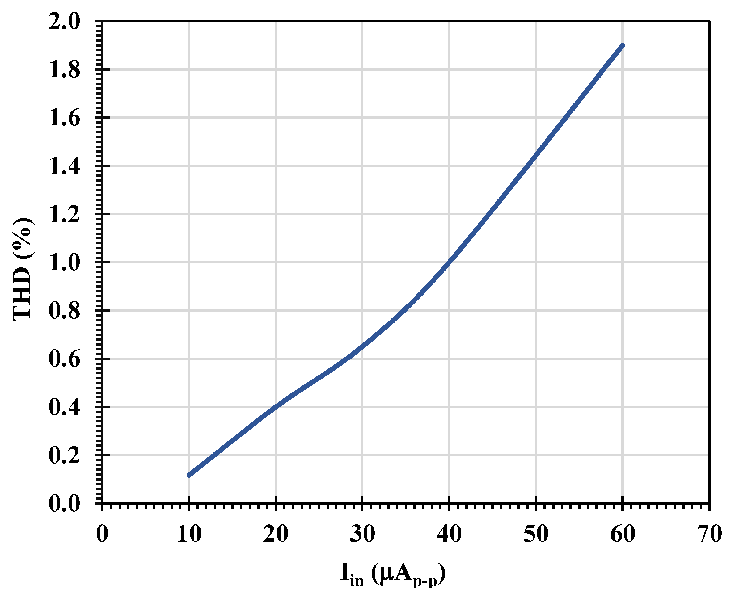
| Total harmonic distortion (%) | 1@40 μApp | 1@200 mVpp | 2@30 μApp | <1.5@90 μApp | - | - | - |
| Power supply voltages (V) | ±2.5 | ±5 | ±0.9 | ±0.75 | ±1.25 | ±1 | ±0.9 |
| Power consumption (mW) | 2.72 | 57.6 | 1.057 | 4.08 | 1.75 | 2.5 | 1.31 |
| Verification of result | Sim. | Exp. | Sim./Exp. | Sim. | Sim./Exp. | Sim./Exp. | Sim./Exp. |
Disclaimer/Publisher’s Note: The statements, opinions and data contained in all publications are solely those of the individual author(s) and contributor(s) and not of MDPI and/or the editor(s). MDPI and/or the editor(s) disclaim responsibility for any injury to people or property resulting from any ideas, methods, instructions or products referred to in the content. |
© 2023 by the authors. Licensee MDPI, Basel, Switzerland. This article is an open access article distributed under the terms and conditions of the Creative Commons Attribution (CC BY) license (https://creativecommons.org/licenses/by/4.0/).
Share and Cite
Kumngern, M.; Jongchanachavawat, W.; Phatsornsiri, P.; Wongprommoon, N.; Khateb, F.; Kulej, T. Current-Mode First-Order Versatile Filter Using Translinear Current Conveyors with Controlled Current Gain. Electronics 2023, 12, 2828. https://doi.org/10.3390/electronics12132828
Kumngern M, Jongchanachavawat W, Phatsornsiri P, Wongprommoon N, Khateb F, Kulej T. Current-Mode First-Order Versatile Filter Using Translinear Current Conveyors with Controlled Current Gain. Electronics. 2023; 12(13):2828. https://doi.org/10.3390/electronics12132828
Chicago/Turabian StyleKumngern, Montree, Wirote Jongchanachavawat, Punnavich Phatsornsiri, Natapong Wongprommoon, Fabian Khateb, and Tomasz Kulej. 2023. "Current-Mode First-Order Versatile Filter Using Translinear Current Conveyors with Controlled Current Gain" Electronics 12, no. 13: 2828. https://doi.org/10.3390/electronics12132828