Article

A Sub-Synchronous Oscillation Suppression Strategy Based on Active Disturbance Rejection Control for Renewable Energy Integration System via MMC-HVDC

1
State Grid Fujian Electric Power Research Institute, Fuzhou 350007, China
2
Fujian Key Laboratory of Smart Grid Protection and Operation Control, Fuzhou 350007, China
3
College of Electrical Engineering, Sichuan University, Chengdu 610065, China
*
Author to whom correspondence should be addressed.
Electronics 2023, 12(13), 2885; https://doi.org/10.3390/electronics12132885
Submission received: 26 April 2023 / Revised: 27 June 2023 / Accepted: 28 June 2023 / Published: 29 June 2023

Abstract

:
To realize the consumption of renewable energy such as wind power and photovoltaics in the power system, renewable energy integration system via modular multilevel converter (MMC)-based high voltage direct current (MMC-HVDC) has been widely applied. However, with the large-scale grid connection of renewable energy units, sub-synchronous oscillation (SSO) is prone to occur. Aiming at the problem, this paper proposes an SSO suppression strategy for renewable energy integration system via MMC-HVDC based on active disturbance rejection control (ADRC) theory. Using the direct drive permanent magnet synchronous generators (PMSG)-based wind farm integration system via MMC-HVDC as an example, firstly the topology and control system principles of the system are described, and a simulation model is built in PSCAD/EMTDC. Moreover, the SSO mechanism of the system is revealed by Nyquist stability criterion, and the major factors affecting the SSO of the system are simulated and analyzed. Subsequently, an additional sub-synchronous damping controller (ASSDC) is proposed based on ADRC theory. Compared to traditional additional damping controllers, the proposed controller considers disturbances of the system during the designing process and has stronger robustness. In addition, when faults happen, the speed of the system with ASSDC reaching a steady-state operating point rises by 33.7% as compared to the system without ASSDC. Finally, the effectiveness of the proposed suppression strategy is verified through simulation analysis.

1. Introduction

Modular multilevel converter (MMC)-based high voltage direct current (MMC-HVDC) has been demonstrated to be an efficient way for integrating renewable energy due to low harmonic content, flexible control, and low switching frequency [1,2]. In addition, it has been widely utilized in many practical projects to realize the consumption of renewable energy. However, with the large-scale grid connection of renewable energy, sub-synchronous oscillation (SSO) accidents have occurred many times in practical projects such as Nanao MMC-HVDC project [3] and Zhangbei flexible DC power grid [4,5], which leads to wind turbine disconnection, power quality issues, and so on [6].
Currently, the SSO suppression methods for renewable energy integration system can be divided into three categories: parameter optimization, adding SSO suppression devices, and adding additional damping control. Among them, the parameter optimization method is simple to use and inexpensive to implement. Reference [7] analyzed the influence of grid-side converter’s parameters on the equivalent damping and suggested a parameter optimization method based on particle swarm optimization algorithm (PSO), whose validity was verified by simulation. Reference [8] optimized the parameters of the grid connected inverter and the wind farm side MMC (WFMMC), respectively, to suppress SSO occurred in wind farm integration system via MMC-HVDC. On this basis, the damping coupling of SSO/super-synchronous oscillation (SupSO) caused by wind power delivery systems was considered in [9] and a coordinated optimization method which selected maximizing the damping ratios of the oscillation modes as optimization object was proposed to suppress the SSO/SupSO. However, when the control system is complicated and control parameters are numerous, there may be coupling between the control parameters [10]. The damping of different oscillation modes may become worse due to improper parameters, and parameter optimization will become more challenging [11]. As for adding SSO suppression devices, references [12,13,14] proposed to add flexible AC transmission systems (FACTS) such as STATCOM to system to restrain the SSO. In addition, it was proved that a renewable energy hydrogen production system (HPS) can mitigate SSO in [15]. Although adding SSO suppression devices has a good suppression impact and a quick response time, it has poor economics [16]. In terms of additional damping control, reference [3] added an SSO suppression controller to the control system of the WFMMC to suppress the SSO of the output current of the wind farm. Although the approach can significantly increase sub-synchronous damping, it pays little attention to the suppression ability of wind turbine converter. Regarding this issue, an SSO damping controller was proposed for double-fed induction generator (DFIG)-based wind farms and the optimum parameters of the controller were obtained by improved PSO in [17], which not only suppressed SSO effectively but also improved the dynamic performance of the system. In [18], it was found that phase-locked loop parameters were key factors affecting the stability of the wind farm integrated system and an additional damping controller was added to PLL to suppress SSO. Reference [19] proposed a damping control strategy for DFIG-based wind farm integrated system to damp SSO, whose performance was proven on a simulation model of a real-world wind power system. Moreover, the effectiveness of additional damping control in both converter stations of an MMC-HVDC and wind turbines was analyzed in [20], and it was proven that additional damping control can dampen SSO under different operating conditions. However, the aforementioned references rarely consider disturbances of the system when designing controllers. The performance of additional damping controllers will be significantly impacted and their robustness will be poor in the presence of disturbances in the system or when the operating point of the system is far from the initial operating point.
In this article, an additional sub-synchronous damping controller (ASSDC) is proposed based on the theory of active disturbance rejection control (ADRC) for renewable energy integration system via MMC-HVDC. Compared to traditional additional damping controllers, the proposed controller considers system disturbances during the designing process and has stronger robustness. Taking direct drive permanent magnet synchronous generators (PMSG)-based wind farm integration system via MMC-HVDC as an example, the main contributions of this article are summarized as follows:
(1) Based on the topology and control principles of the PMSG-based wind farm integration system via MMC-HVDC, a simulation model in PSCAD/EMTDC is established and the impedance characteristics of the wind farm and MMC subsystems are obtained by frequency scanning. Using Nyquist stability criterion, the mechanism of SSO in system is revealed.
(2) An additional sub-synchronous damping controller based on ADRC is proposed, which takes system disturbances as a new state variable of the controller, so it can adapt to different operating conditions and has stronger robustness under various disturbances.
The rest of the article is organized as follows: Section 2 introduces the topology and control system of the PMSG-based wind farm integration system via MMC-HVDC and establishes a simulation model in PSCAD/EMTDC. Then, the stability of the system is analyzed using Nyquist stability criterion and main factors influencing SSO are acquired by simulation analysis in Section 3. Section 4 suggests an additional sub-synchronous damping controller and describes how to tune its control parameters. The effectiveness of the proposed SSO suppression method is verified in Section 5 through simulation analysis. Finally, Section 6 draws the conclusion.

2. Modeling of PMSG-Based Wind Farm Integration System via MMC-HVDC

Establishing a model of the PMSG-based wind farm integration system via MMC-HVDC is one of the vital parts that analyzing the stability of the system. In this section, the topological structure and control principles of the system are initially introduced. On the basis of it, a simulation model in PSCAD/EMTDC is built and its accuracy is investigated.

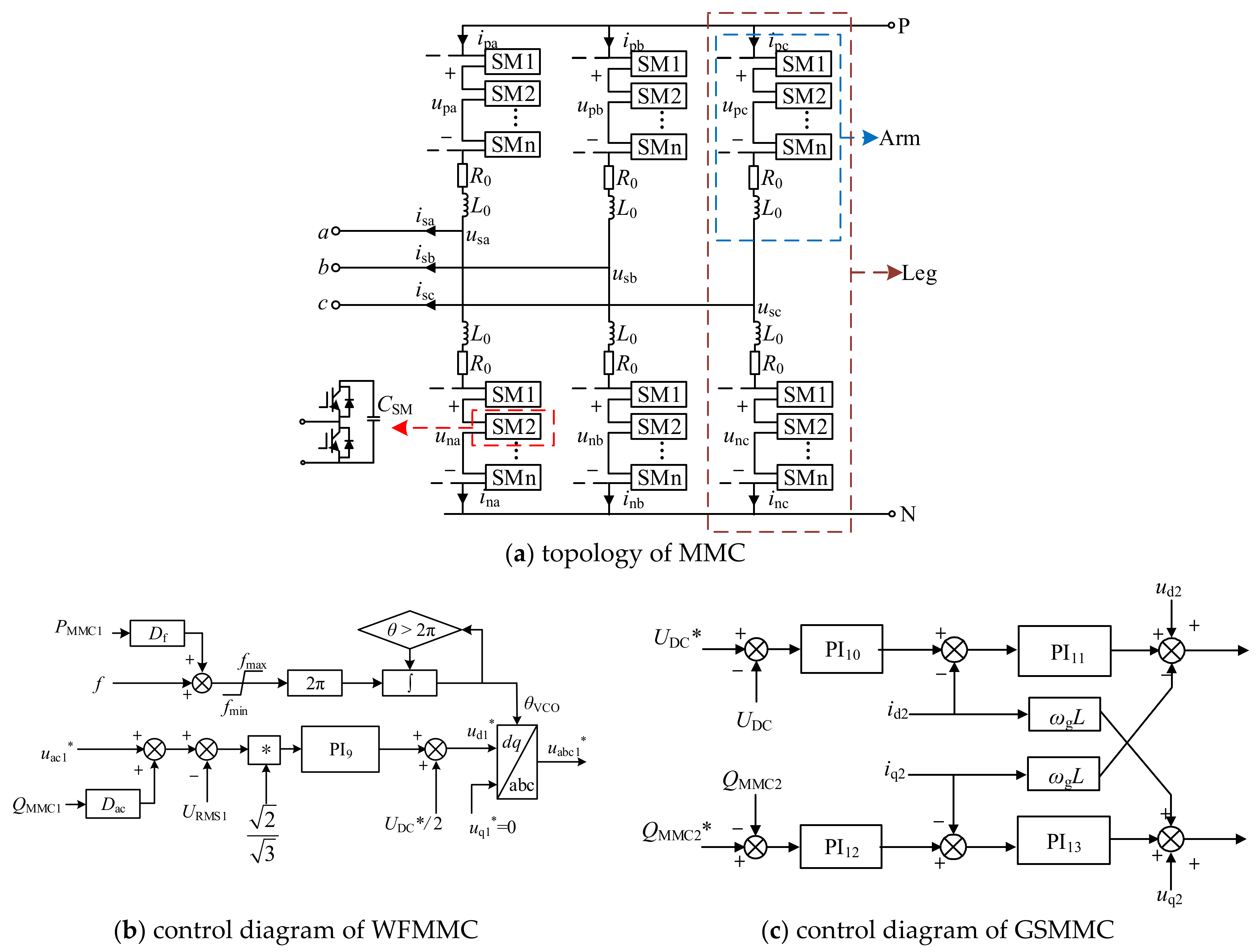
2.1. Topology and Control Principles of the System

Figure 1 shows the topological structure of the PMSG-based wind farm integration system via MMC-HVDC, which includes a PMSG-based wind farm (WF), a transformer station, high-voltage AC cables, a WFMMC station, high-voltage DC cables, and a grid side MMC (GSMMC) station. The wind farm is composed of 200 identical wind turbines with a total installed capacity of 500 MW. Then, the voltage level is stepped up from 35 kV to 220 kV, and the 220 kV bus as the point of common coupling (PCC) is connected to the WFMMC station for conversion into ±320 kV DC. In addition, the rated capacity of MMC-HVDC is 600 MVA, and the length of DC cables is 200 km.
The configuration and control system of a PMSG-based wind energy conversion system (WECS) are displayed in Figure 2, mainly including wind turbine, permanent magnet synchronous generator, machine side converter (MSC) and corresponding control system, grid side converter (GSC), and its control system [21,22]. Both MSC and GSC adopt dq decoupling control, where the outer loop of MSC controls active power PMS and AC voltage umabc, the outer loop of GSC controls DC voltage Udc and output reactive power QGS. The inner loops are current control loops. In addition, proportional-integral controllers are adopted in outer and inner loops.
In Figure 2, PMS* is the reference value of active power, which is provided by the maximum wind energy tracking module of the wind turbine; PMS is the actual active power generated by the PMSG; UmRMS and UmRMS* are the root mean square (RMS) value of the AC voltage umabc and its reference value at the output port of the generator, and UmRMS* = 1.0 p.u; imd, imq, are dq components of output current imabc of the generator; θr is the result of rotor angle multiplying by the number of pole pairs; ωs is the angular speed; Ls is the stator inductance of the generator. Udc and Udc* refer to the DC bus voltage and reference value; QGS and QGS* represents reactive power of the GSC and its reference value; igd and igq are dq components of output current igabc of the GSC; ugd and ugq are the dq components of the output voltage ugabc, respectively; ωg is the synchronous angular velocity of the AC grid; θg is the phase angle of ugabc output by phase-locked loop (PLL); Cdc is DC capacitor; Lg is the equivalent inductance of the incoming reactor of the GSC; PGS represents active power of the GSC; PWECS, iGabc, and uGabc are output active power, currents, and voltages of the aggregated PMSG-based WECS. The blue arrow represents the reference direction of the system currents.
Figure 3a presents the topology of MMC used for WFMMC and GSMMC. One upper arm and one lower arm are connected in series between the DC terminals to form each phase leg of the MMC. N identical series-connected submodules (SMs) make up each arm, along with an inductor L0 and an arm-equivalent series resistor R0. Each SM contains a capacitor CSM and a half bridge as the switching element. In this paper, WFMMC adopts island droop control, whose control diagram is shown in Figure 3b. GSMMC adopts constant DC voltage control and constant reactive power control, and the control diagrams is displayed in Figure 3c.
In Figure 3b,c, Df and Dac are droop control coefficients; fmax and fmin are the limits of frequency; f is the frequency of PCC1; uac1* is the reference value of the AC voltage uabc1 at PCC1 and URMS1 is the RMS value of uabc1; UDC and UDC* are the DC voltage and its reference value; L is the equivalent inductance of the AC grid; PMMC1 and QMMC1 are active and reactive power of WFMMC; QMMC2 and QMMC2* are reactive power of GSMMC and its reference value; ud1 and uq1 are dq components of uabc1; ud2 and uq2 are dq components of the AC voltage uabc2 at PCC2; id2 and iq2 are dq components of the AC current iabc2 at PCC2.

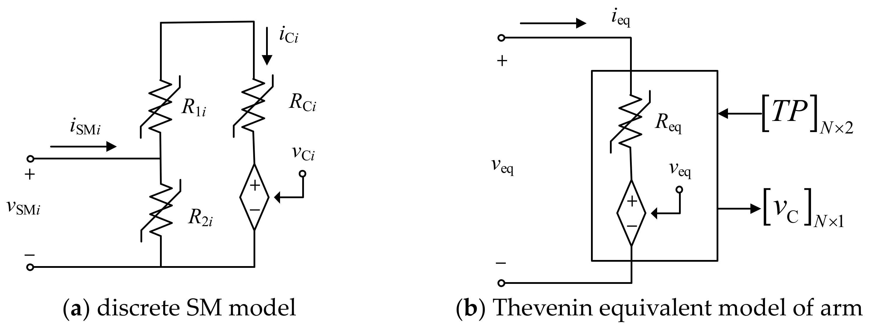
2.2. Simulation Model of the System

Based on the topological structure and control diagram of the aforementioned system, a model of the PMSG-based wind farm integration system via MMC-HVDC is constructed in PSCAD/EMTDC. In this simulation model, the wind farm is modeled by an aggregated PMSG-based WECS using equivalent processing to simplify the analysis. In addition, the original IGBT switch is replaced with a variable resistor switched between milliohm on resistance and megohm off resistance and the CSM of SMs are discretized to overcome the issue of enormous computation caused by too many switching elements [23]. The equivalent Thevenin models of each discrete SM and arm are shown in Figure 4, respectively. Some parameters in the simulation model are shown in Table 1.
The simulation model is validated when wind speed is 7 m/s and the waveforms of output active power PWECS, three-phase voltages uGabc, and three-phase currents iGabc represented by lines with different colors of the aggregated PMSG-based WECS are shown in Figure 5. Figure 6 displays the voltage UDC and current IDC waveforms of the DC cables, where the red lines represent the voltage and current of the positive DC cables and the green lines represent the voltage and current of the negtive DC cables [24,25,26].
Figure 5 and Figure 6 show that the simulation model can operate near the given values and soon reach a stable state. As a result, the simulation results confirm the viability of equivalent processing of the wind farm and MMC-HVDC models, as well as the correctness of the control strategies of the system.

3. Stability Analysis and Key Influencing Parameters Analysis of the System

Based on the simulation model established in Section 2, the impedance characteristics of the wind farm and MMC subsystems are obtained by frequency scanning and the stability of the system is analyzed using Nyquist stability criterion in this section. Additionally, the main factors affecting the SSO of the PMSG-based wind farm integration system via MMC-HVDC are analyzed by simulation.

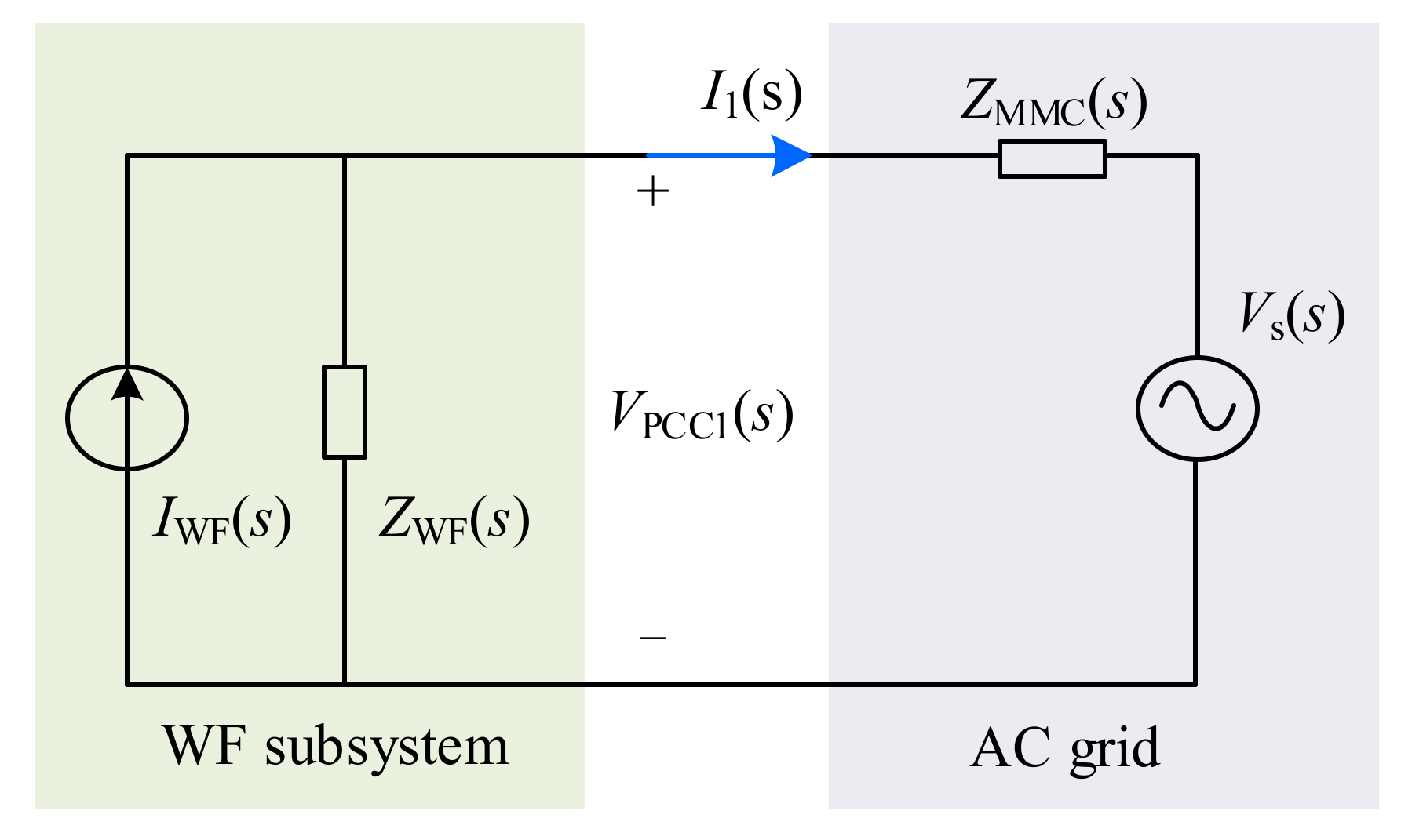
3.1. Stability Analysis of the System

The PMSG-based wind farm integration system via MMC-HVDC can be seen as a cascade of the wind farm and MMC subsystems as shown in Figure 1. According to [27], the cascade system can be equivalent to the small signal model shown in Figure 7. The aggregated PMSG-based WECS can be equivalent to an ideal current source IWF(s) and an impedance ZWF(s) in parallel since the inverter employ current control method. WFMMC is equivalent to an ideal voltage source Vs(s) and an impedance ZMMC(s) in series because of the AC voltage control strategy. The equivalent impedance of the system can be calculated without taking into account the AC cable’s impedance because the distance between the wind farm and the WFMMC station is often short.
The output current I1(s) and voltage VPCC1(s) at PCC1 can be expressed as follows:
I 1 ( s ) = I WF ( s ) V s ( s ) Z WF ( s ) 1 1 + Z MMC ( s ) / Z WF ( s )
V PCC 1 ( s ) = Z MMC ( s ) I WF ( s ) + V s ( s ) 1 1 + Z MMC ( s ) / Z WF ( s )
The stability of the system depends on whether the impedance ratio ZMMC(s)/ZWF(s) of the two cascaded subsystems meets the Nyquist stability criterion when the subsystems are stable under the ideal voltage source, respectively. When the amplitude-frequency characteristics of ZWF(s) and ZMMC(s) have an intersection point and the phase difference at the intersection point is close to or greater than 180°, there is a risk of oscillation in the system.
The curves of ZWF(s) and ZMMC(s) are obtained by adding a frequency scanning module to the PCC1 of the simulation model, which is shown in Figure 8. Because this paper mainly focuses on the stability of the sub-synchronous frequency band, Figure 8 only shows the impedance characteristic curves of the sub-synchronous frequency band.
According to Figure 8, the amplitude-frequency characteristic curves of ZWF(s) and ZMMC(s) have an intersection point at 29.2 Hz, and the phase difference at the intersection point is 174.73°, which is obviously insufficient. Therefore, the system has the risk of SSO.

3.2. Analysis of Key Influencing Parameters

The stability of the PMSG-based wind farm integration system via MMC-HVDC is easily affected by external factors and control parameters of control loops. In this subsection, it is studied that the influence of wind speed and controller parameters of the MSC and GSC on system stability.

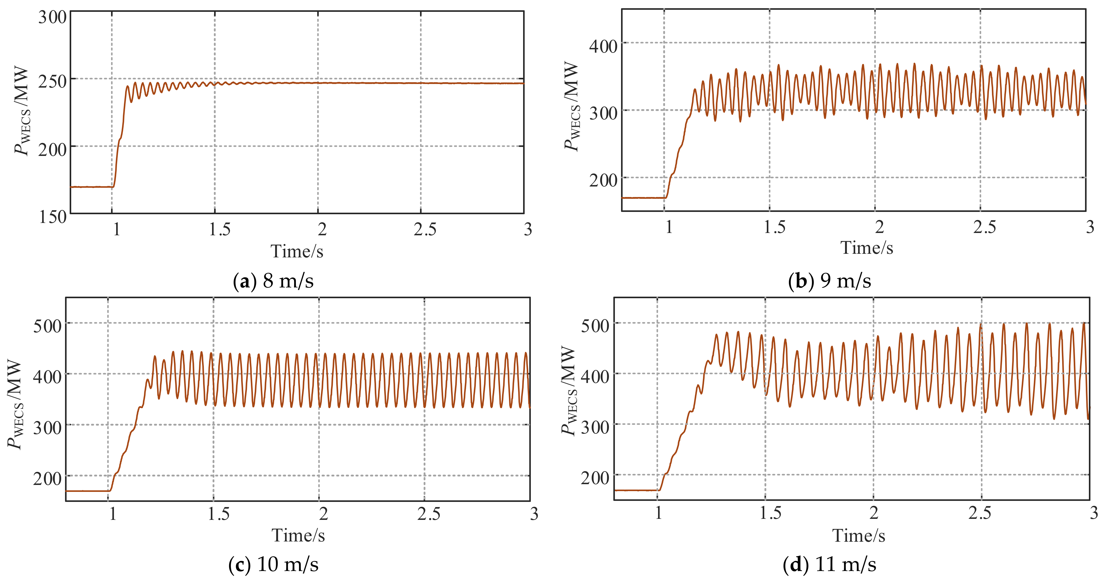
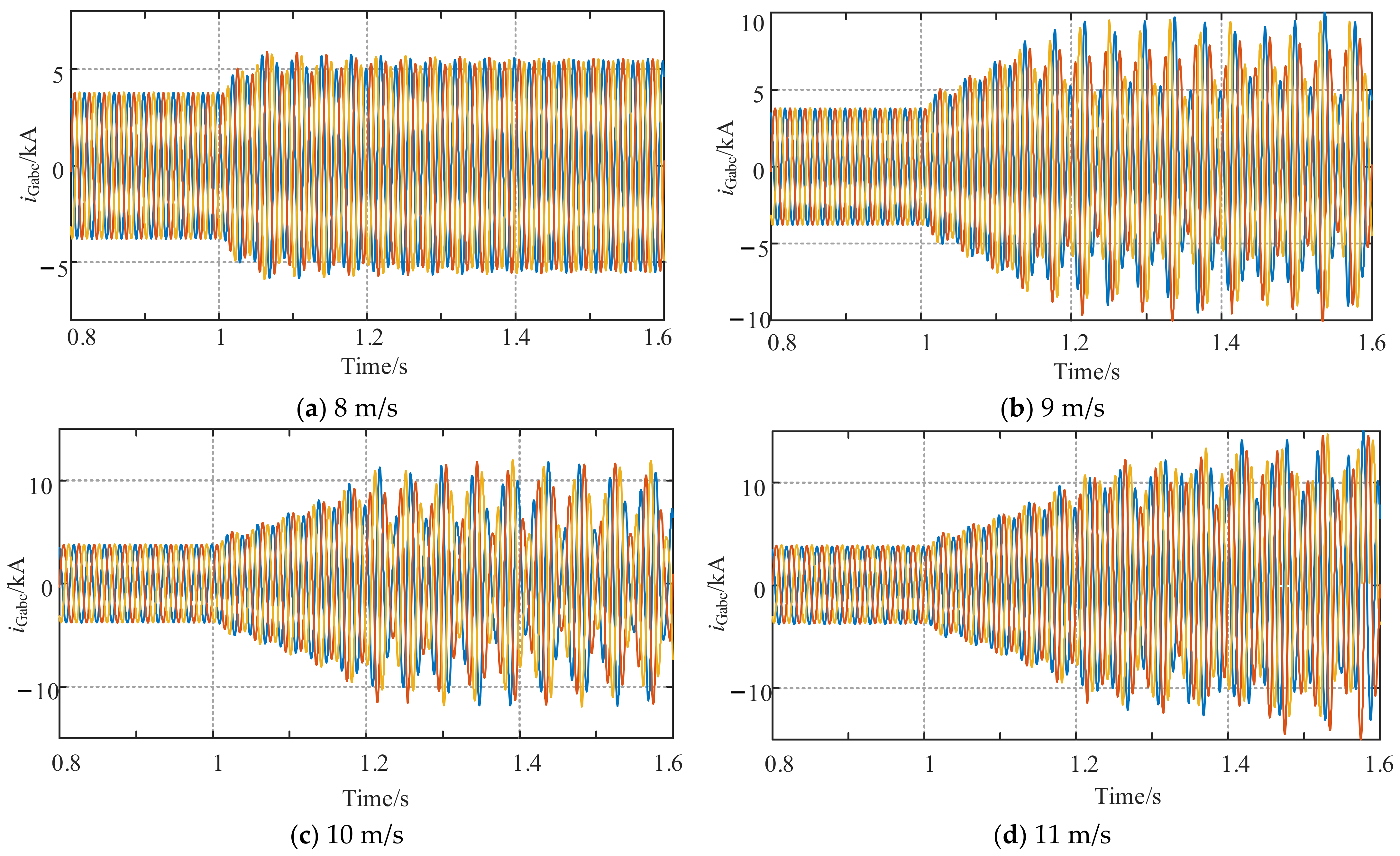
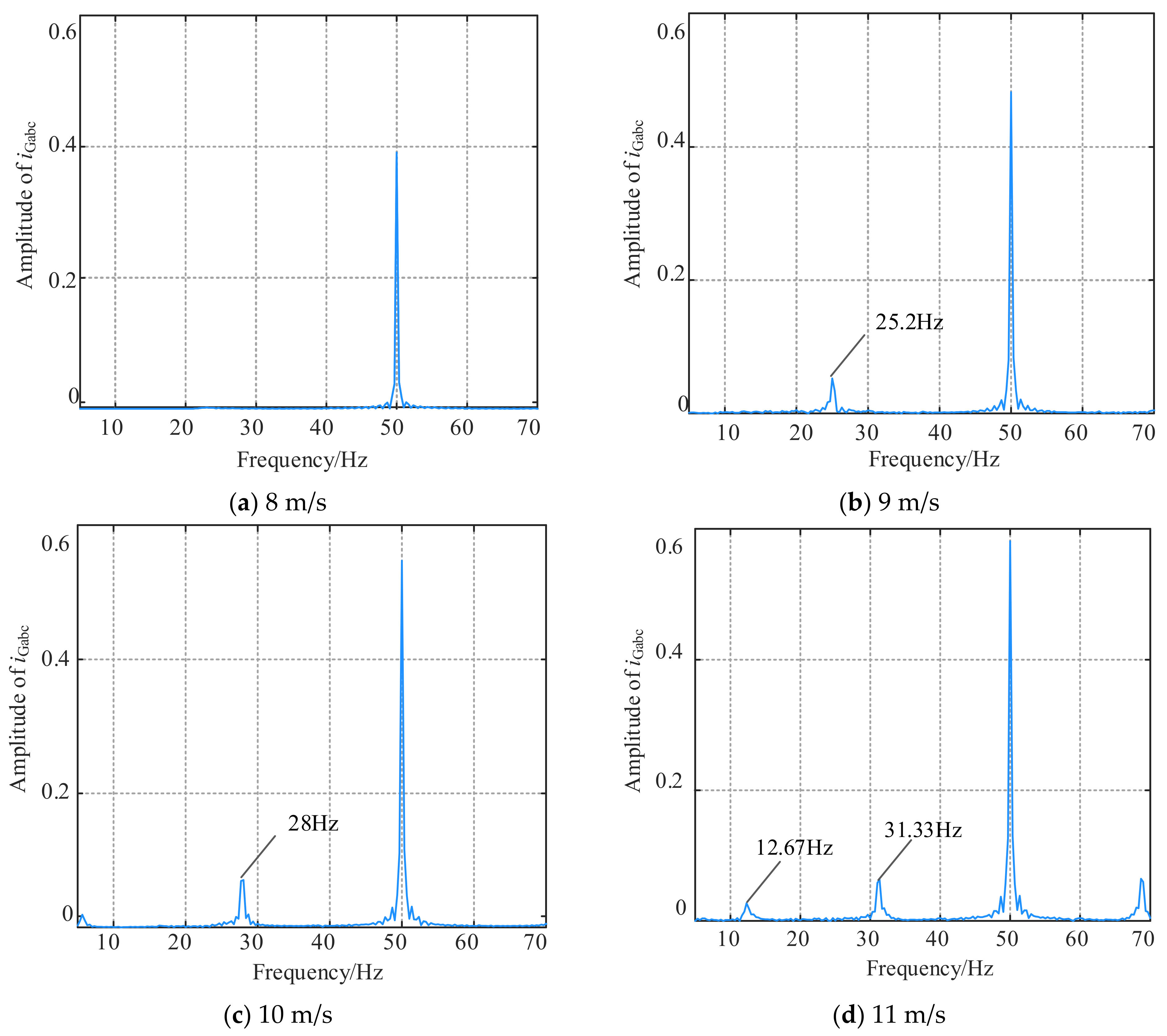
3.2.1. Impact of Wind Speed

The output power of the wind farm is unpredictable and uncontrollable because of the impact of wind speed, which causes it to fluctuate widely. In order to simplify the analysis, it is assumed that the wind speed is equal and changes synchronously of each wind field. The initial wind speed is set as 7 m/s, and the wind speed is changed when t = 1.0 s. As the wind speed increases, the output active power PWECS and currents iGabc of the aggregated PMSG-based WECS are observed, as shown in Figure 9 and Figure 10, respectively.
As seen from Figure 9 and Figure 10, the system oscillates in a tiny amplitude and rapidly converges, reaching a new stable state without visible oscillation when the wind speed reaches 8 m/s; when the wind speed is changed to 9 m/s, the system oscillates; when the wind speed is changed to 10 m/s, the output active power of the wind farm maintains constant amplitude oscillation; when the wind speed is changed to 11 m/s, the oscillation becomes more intense and exhibits a divergent trend, which eventually causes the system to become unstable. The corresponding Fourier analysis results of the output current can be obtained, shown in Figure 11.
As demonstrated in Figure 11, the oscillation frequency of the output current is 25.2 Hz when the wind speed is set to 9 m/s. When the wind speed is increased to 10 m/s, the SSO intensifies and the oscillation frequency at the moment is 28 Hz. The SSO of the system is amplified and a new oscillation frequency emerges when the wind speed is changed to 11 m/s. The oscillation frequencies are 12.67 Hz and 31.33 Hz, respectively.
The analysis presented above leads to the conclusion that the output active power of the aggregated PMSG-based WECS increases and the SSO worsens when wind speed increases. Additionally, as the wind speed increases, the oscillation frequency changes, and a new oscillation frequency even appears in the sub/super-synchronous frequency band.

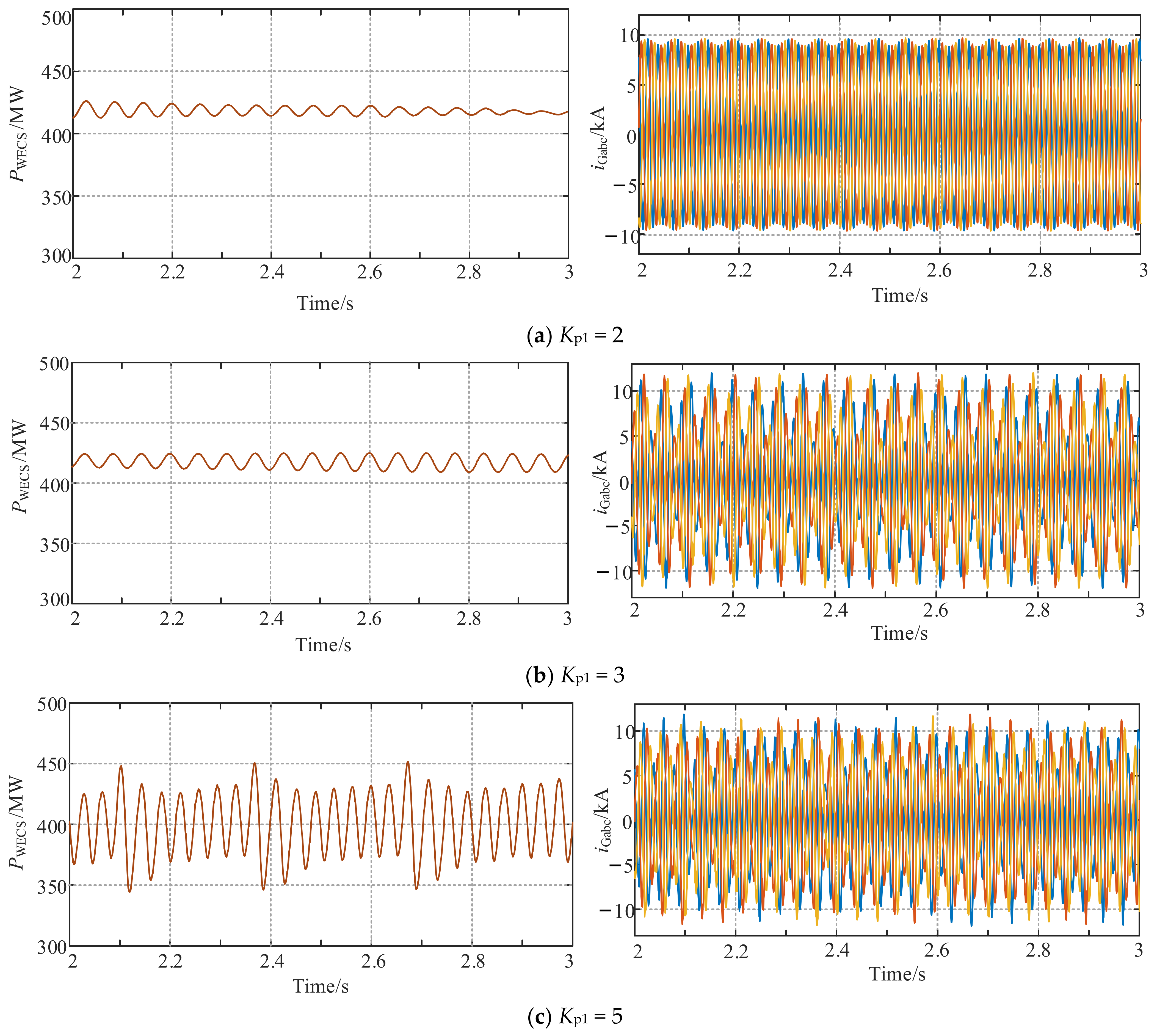
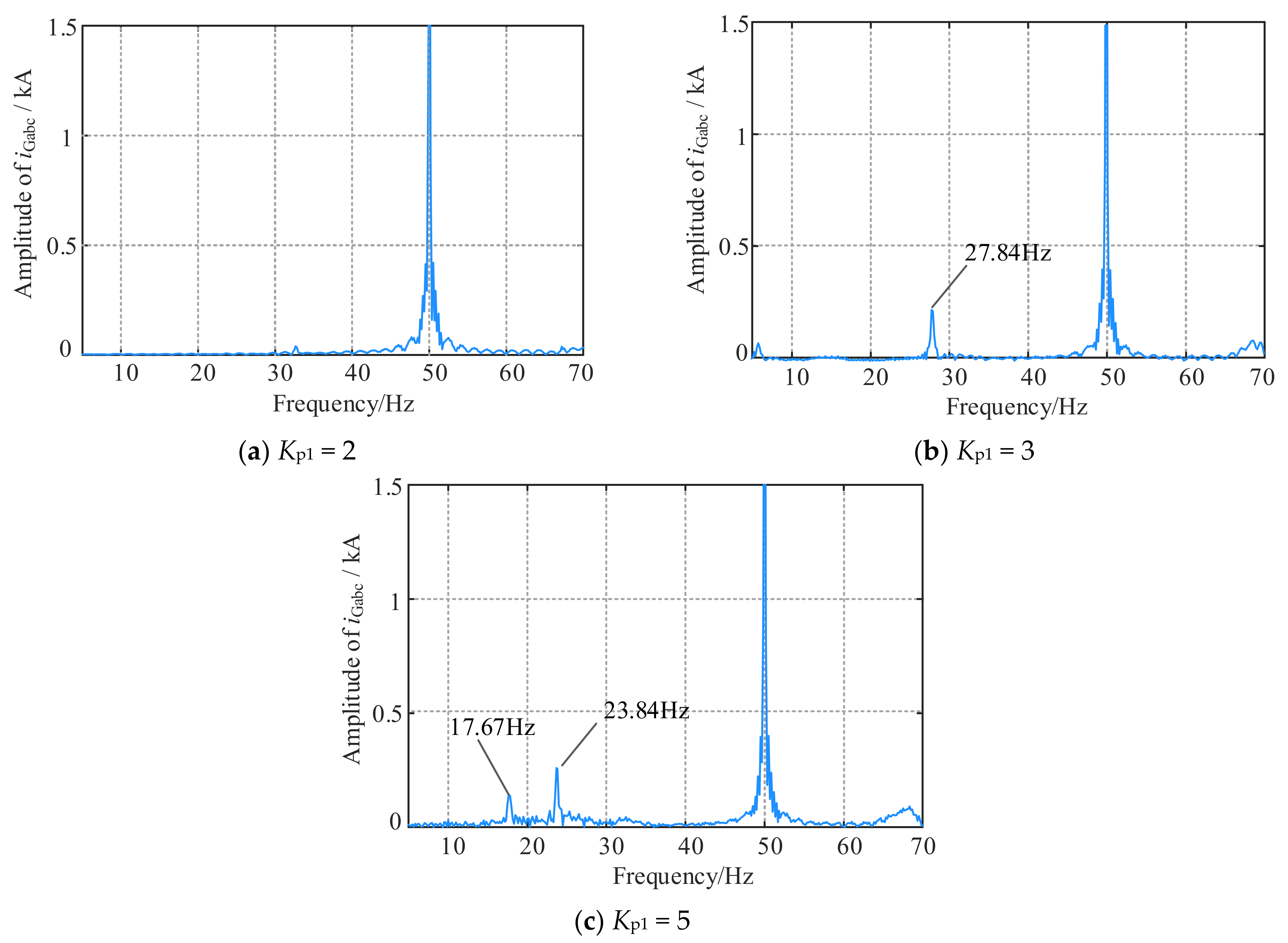
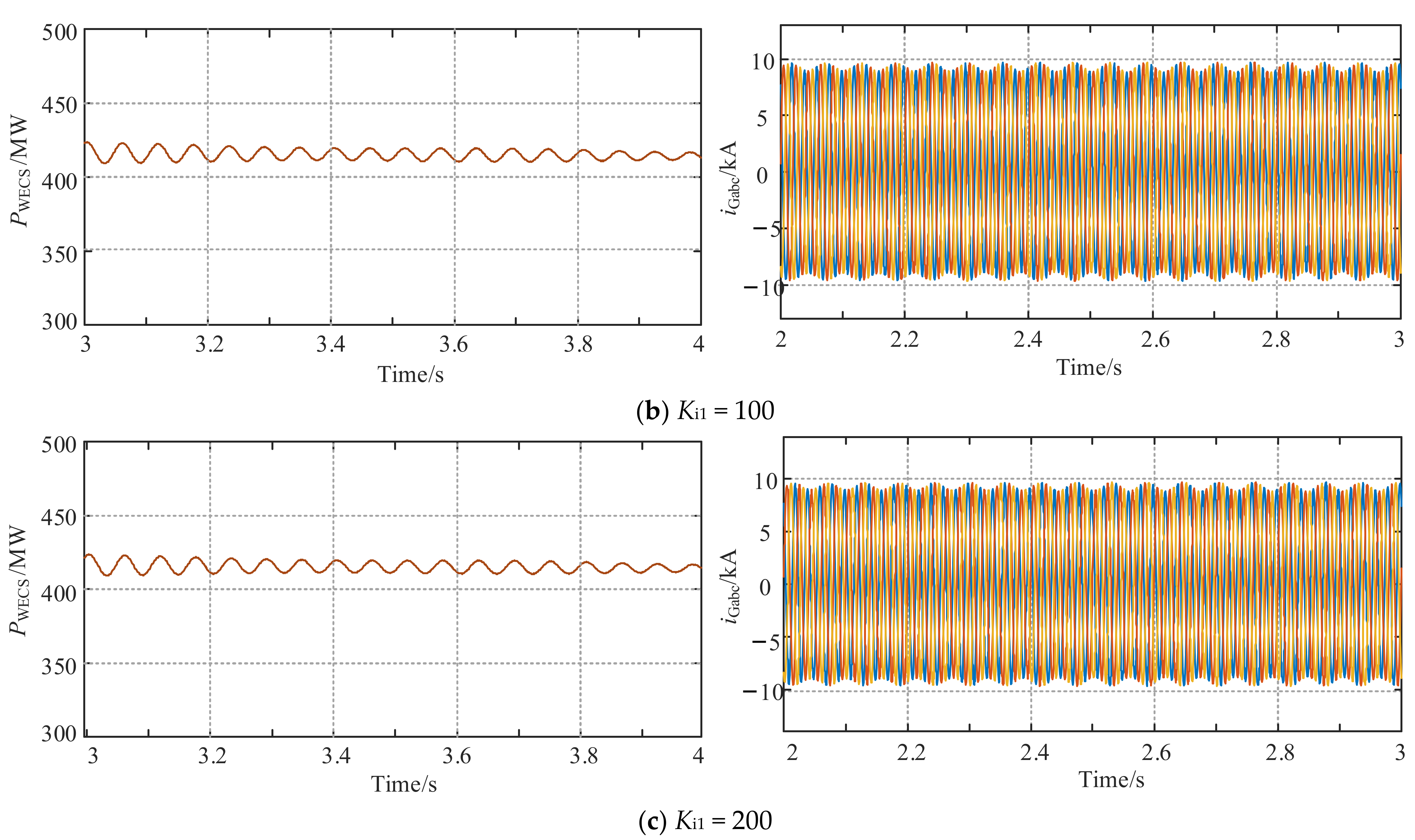
3.2.2. Impact of Control Parameters

In this subsection, the influence of control parameters of the aggregated PMSG-based WECS on SSO is analyzed, mainly considering the controller parameters of inner loops of the MSC and GSC [28].
(1) Parameters of MSC inner loop controller
Change the proportional coefficient Kp1 of MSC inner loop controller and set it as: (a) Kp1 = 2; (b) Kp1 = 3; (c) Kp1 = 5. The waveforms of the active power and current of the aggregated PMSG-based WECS are shown in Figure 12. Fourier analysis results of the current are shown in Figure 13.
As can be seen from Figure 12 and Figure 13, the oscillation frequency 27.84 Hz appears in the system when Kp1 = 3. When Kp1 = 5, the system oscillates at 17.67 Hz and 23.84 Hz. Compared with the former, the oscillation frequency of the system decreases, and the oscillation frequency points are increased. It can be concluded that with the increase in Kp1, the system oscillates at other frequencies except the fundamental frequency and the oscillation frequency decreases gradually. However, it can be seen from Figure 13 that the system will not become unstable through the above adjustment of Kp1.
Change the integral coefficient Ki1 of MSC inner loop controller and set it as: (a) Ki1 = 30; (b) Ki1 = 100; (c) Ki1 = 200. The waveforms of the active power and current are shown in Figure 14. As can be seen from Figure 14, changing Ki1 has no significant effect on the oscillation of the system.
(2) Parameters of GSC inner loop controller
Change the proportional coefficient Kp2 of GSC inner loop controller as follows: (a) Kp2 = 1; (b) Kp2 = 2; (c) Kp2 = 3. The waveforms of the active power and current are shown in Figure 15.
As demonstrated in Figure 15, the oscillation of the system converges when Kp2 = 1 and Kp2 = 2, and the oscillation amplitude grows as Kp2 increases. The oscillation diverges and the system becomes unstable when Kp2 = 3. FFT analysis is performed on the current, and the outcomes are displayed in Figure 16.
As shown Figure 16, the fundamental frequency is the only frequency in the system that oscillates visibly when Kp2 = 1 and Kp2 = 2. Sub-synchronous and super-synchronous oscillations happen concurrently when Kp2 = 3 and their frequencies are 32.67 Hz and 67.18 Hz, respectively. Therefore, the following conclusions can be drawn: as Kp2 increases, the oscillation amplitude of the system increases, and the oscillation will diverge when Kp2 increases to a certain value.
According to the simulation results, changing the integral coefficient Ki2 of GSC inner loop controller has no impact on the oscillation of the system. Therefore, it is not thoroughly examined here.
The above analysis shows that changing Ki1 and Ki2 has no obvious impact on system oscillation. Changing Kp1 and Kp2 has some impact on the system oscillation. The system will oscillate at other frequencies except the fundamental frequency but will not become unstable when Kp1 changes, while changing Kp2 can cause the system to become unstable. Therefore, it may be said that Kp2 is the key factor affecting the sub/super-synchronous oscillation of the system.

4. Design of An Additional Sub-Synchronous Damping Controller Based on ADRC

The proportional coefficient Kp2 of the GSC inner current control, which was examined in the previous section, is a crucial factor in the SSO. Therefore, the parameter design of the current loop controller in GSC plays a vital role in the system stability. The existing PI controller, however, suffers from control lag and there is coupling among the control parameters, making it challenging to suppress oscillations through parameter tuning. This section suggests an additional sub-synchronous damping controller (ASSDC) based on ADRC for the PMSG-based wind farm integration system via MMC-HVDC.

4.1. Active Disturbance Rejection Control Theory

ADRC does not depend on an accurate model of the system and estimates the disturbance in real-time, making it adaptable to various operating conditions and highly robust [29,30]. The control diagram, as shown in Figure 17, includes four parts: tracking differentiator, extended state observer, nonlinear state error feedback, and control signal generation loop.
(1) Tracking differentiator (TD)
The function of TD is to achieve fast tracking of the input signal and synchronous output differential signal, which can solve the conflict between overshoot and rapidity in traditional PID control. The mathematical expression of TD is expressed as follows:
fh = fhan ( v 1 v , v 2 , r 0 , h 0 ) v ˙ 1 = v 1 + h v 2 v ˙ 2 = v 2 + h fh
where v1 can track the control input v without overshoot and v2 is the approximate differentiation of v. h is the sampling period, r0 is the tracking speed factor, h0 is the filtering factor, and fhan is the comprehensive function, which has a specific mathematical expression in [31].
(2) Extended state observer (ESO)
The ESO expands the total disturbance into a new state variable of the system, and uses feedback compensation to track the signal and eliminate the influence of the total disturbance in the system. Its mathematical expression is:
ε 1 = z 1 y z ˙ 1 = z 2 β 01 ε 1 z ˙ 2 = z 3 β 02 fal ( ε 1 , a 1 , δ 1 ) + b 0 u z ˙ 3 = β 03 fal ( ε 1 , a 2 , δ 1 )
where y is the output of the controlled object; z1, z2, and z3 are state variables provided by ESO; u is control variable; β01, β02, β03, a1, and a2 are adjustable parameters of the ADRC; b0 is compensation factor; δ1 is filtering factor; the nonlinear function fal(x, a, δ) is expressed in (5), and δ > 0; sign(x) denotes the sign function.
fal ( x , a , δ ) = x δ 1 a e δ sign ( x ) x a e > δ
(3) Nonlinear State Error Feedback (NLSEF)
NLSEF obtains the error signal e1 = v1z1 and the error differential signal e2 = v2z2 based on the tracking signal output by TD and the signal observed by ESO, and compensates for disturbances by nonlinear combination to control the corresponding object, whose purpose is to suppress and eliminate disturbances.
There are generally two forms of nonlinear combinations, shown in Equations (6) and (7), respectively. In (6) and (7), c is the damping factor; r is the control gain; and h1 is the precision factor; β1, β2, a3, and a4 are adjustable parameters. In this paper, (6) is selected.
u 0 = β 1 fal ( e 1 , a 3 , δ 2 ) + β 2 fal ( e 2 , a 4 , δ 2 )
u 0 = fhan ( e 1 , c e 2 , r , h 1 )
(4) Control signal generation loop
The mathematical expression of the control variable can be obtained from Figure 17, shown as follows:
u = u 0 z 3 b 0
where −z3/b0 is the compensation for disturbance, and u0/b0 is the part that uses nonlinear feedback to control the integral cascade.

4.2. Additional Sub-Synchronous Damping Controller Based on ADRC

The previous subsection describes the control structure of the proposed ASSDC based on ADRC. To effectively suppress the SSO and promote the robustness of the system, it is also necessary to determine the input and output signals of the proposed controller and its parameters. This subsection will introduce the position of the controller within the PMSG-based wind farm integration system and the procedure for adjusting control parameters.
(1) Position of the controller and choice of the control signal
The input signal of the ASSDC needs to accurately reflect the characteristics of the SSO of the system and be easy to measure and control. Based on the analysis of the impact of wind speed on SSO in Section 2 and considering external disturbances in the system, this subsection takes the θr of the wind turbine as the input signal and adds the control loop to the inner loop control of the GSC. The specific position of the ASSDC in the system is shown in Figure 18.
(2) Optimization of parameters of the ASSDC based on genetic algorithm
It is clear from Section 4.1 that the following parameters need to be adjusted: r0, h, h0, β01, β02, β03, a1, a2, δ1, β1, β2, a3, a4, and δ2. Among them, h needs to be consistent with the actual simulation step size in the simulation model; when h is fixed, h0 is usually an integer multiple of h to achieve the filtering effect; r0 is typically set to 1000 [32]. In ESO, the values of a1 and a2 are usually taken as 0.5 and 0.25, respectively; δ1 is generally set to h; in NLSEF, 0 < a3 < 1<a4, and δ2 can generally be set between 5h and 10h. Therefore, the parameters that need to be tuned in practice are β01, β02, β03, β1, and β2.
In this subsection, genetic algorithm (GA) [33] is used to tune and optimize the above five parameters, and the ITAE criterion is selected as the fitness function for performance evaluation. The expression of the fitness function is shown in (9).
J = 0 t P WECS * P WECS d t + 0 t Q WECS * Q WECS d t + 0 t U dc * U dc d t
where PWECS*, PWECS, QWECS*, and QWECS represent the reference and actual values of active and reactive power of the aggregated PMSG-based WECS, respectively; Udc* and Udc represent the reference and actual values of the DC bus voltage of the wind turbine; t is simulation time.
The specific optimization process is shown in Figure 19, and the parameter settings of the GA are shown in Table 2.

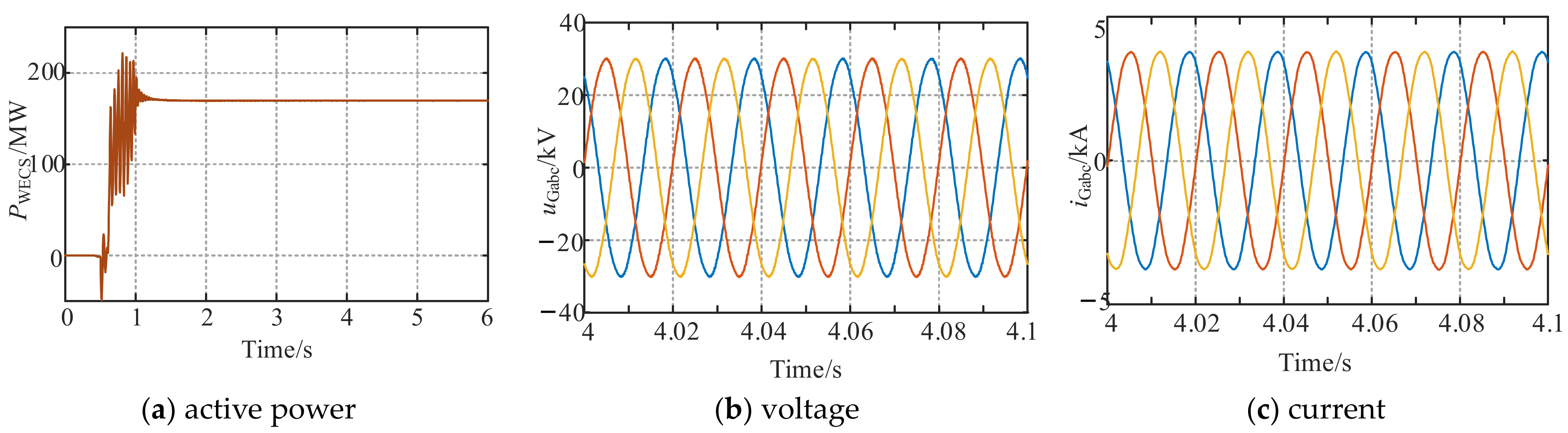
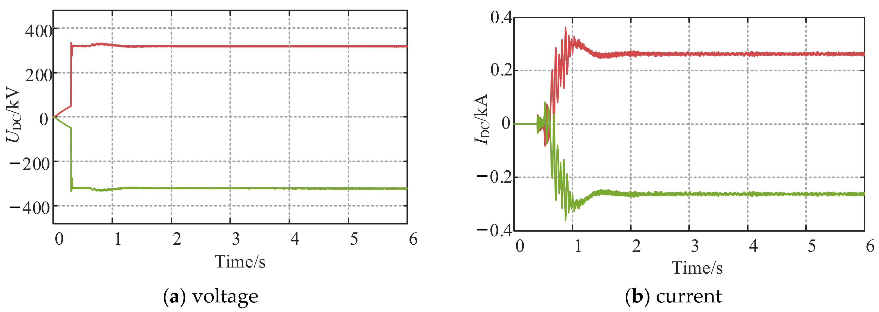
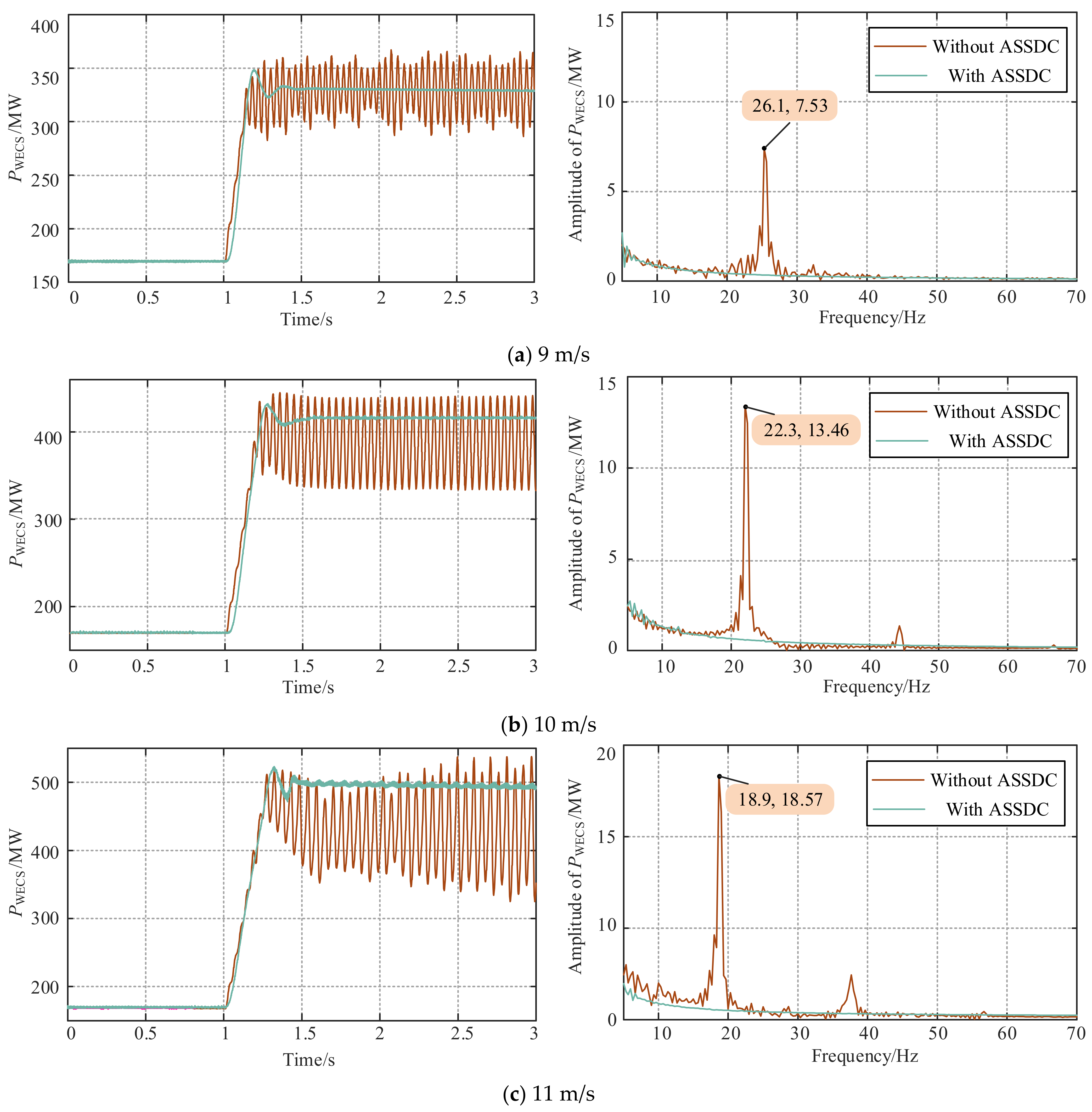
5. Simulation Verification

This section adds the ASSDC proposed in Section 4 to the model built in Section 1, and uses the optimized control parameters of ASSDC for simulation to verify the oscillation suppression effect of the controller under different wind speed and system faults.
(1) Effectiveness verification when wind speed changes
To verify the effectiveness of ASSDC in suppressing SSO under different wind speeds, the wind speeds are set to 9 m/s, 10 m/s, and 11 m/s. The corresponding output active power of the aggregated PMSG-based WECS and FFT analysis results are shown in Figure 20.
It can be seen from Figure 20 that the system can quickly reach a new stable state after adding the ASSDC, and the frequency components of SSO in the active power are much diminished. As the wind speed increases, the output active power PWECS of the PMSG-based WECS with ASSDC will also fluctuate slightly, but still accomplish adequate oscillation suppression effect. Therefore, the proposed ASSDC can effectively suppress the SSO of the system under different wind speeds, verifying the robustness of the ASSDC and helping to increase the transmission power of the system.
(2) Effectiveness verification under system fault
A three-phase short circuit to ground fault that lasts for 0.05 s is set in PCC1 when the model runs for 1.0 s. Figure 21 displays the output active power of the PMSG-based WECS with and without ASSDC under the fault and Table 3 is a table of performance comparison. It can be seen that the PWECS of the system without ASSDC has a wide fluctuation range and the minimum value is −100 MW at 1.28 s, indicating that the output active power of the PMSG-based WECS is reversed. The PWECS of the system with ASSDC, however, is always positive and has a narrow range of variation, with a minimum value of 23.1 MW at 1.32 s. The PWECS with ASSDC stabilizes after 0.6 s of the fault removal, while the PWECS without ASSDC still shows significant power fluctuations. Therefore, the proposed ASSDC can effectively suppress the fluctuation of the output active power and the system with ASSDC can reach the stable state faster under the three-phase short circuit to ground fault.

6. Conclusions

This paper uses the PMSG-based wind farm integration system via MMC-HVDC as an example of the SSO issue in large-scale renewable energy integration systems via MMC-HVDC. First, based on the system topology and control system principles, a simulation model of the system is constructed in PSCAD/EMTDC and the stability of the system is analyzed using Nyquist stability criterion and impedance characteristic curves of the wind farm and MMC subsystems obtained through frequency scanning. Then the impact of wind speed and the control parameters of MSC and GSC on SSO is analyzed by simulation, which can be concluded that the proportional coefficient Kp2 of the GSC inner current loop is the key factor affecting the SSO. Subsequently, an ASSDC based on ADRC theory is proposed. Considering external disturbances in the system, the ASSDC takes the θr of the wind turbine as the input signal and the output signal is added to the inner loop control of the GSC, and GA is utilized to optimize the parameters of the controller. Compared to previous additional damping controllers, this controller does not rely on the precise model of the system and takes into consideration potential disturbances and changes in the system. The ASSDC is able to improve the robustness of the system under disturbances and the recovery speed of system under faults. Finally, the effectiveness and robustness of the proposed ASSDC in suppressing SSO are verified through simulation analysis.

Author Contributions

Conceptualization, W.C., J.L. and Y.W.; methodology, C.D. and J.H.; software, Y.M. and Y.C.; validation, W.C. and J.L.; formal analysis, C.D. and L.D.; investigation, L.D.; resources, L.D.; data curation, Y.M. and J.L.; writing—original draft preparation, Y.C. and Y.M.; writing—review and editing, W.C. and Y.C.; visualization, J.H. and L.D.; supervision, J.L. and Y.W.; project administration, W.C. and Y.W.; funding acquisition, W.C. and Y.W. All authors have read and agreed to the published version of the manuscript.

Funding

This research was supported by the Science and Technology Project of State Grid Fujian Power Co., Ltd. of China (52130422000Y) which is named as Study on Mechanism and Suppression Strategy of DC Oscillation in MMC-HVDC.

Institutional Review Board Statement

Not applicable.

Informed Consent Statement

Not applicable.

Data Availability Statement

Data are contained within the article.

Conflicts of Interest

The authors declare no conflict of interest. The funders had no role in the design of the study; in the collection, analyses, or interpretation of data; in the writing of the manuscript, or in the decision to publish the results.

References

  1. Perez, M.A.; Bernet, S.; Rodriguez, J.; Kouro, S.; Lizana, R. Circuit Topologies, Modeling, Control Schemes, and Applications of Modular Multilevel Converters. IEEE Trans. Power Electron. 2015, 30, 4–17. [Google Scholar] [CrossRef]
  2. Debnath, S.; Qin, J.; Bahrani, B.; Saeedifard, M.; Barbosa, P. Operation, Control, and Applications of the Modular Multilevel Converter: A Review. IEEE Trans. Power Electron. 2015, 30, 37–53. [Google Scholar] [CrossRef]
  3. Lyu, J.; Dong, P.; Shi, G. Subsynchronous Oscillation and Its Mitigation of MMC-Based HVDC With Large Doubly-Fed Induction Generator-Based Wind Farm Integration. Proc. CSEE 2015, 35, 4852–4860. [Google Scholar] [CrossRef]
  4. Li, H.; Shair, J.; Zhang, J.; Xie, X. Investigation of Subsynchronous Oscillation in a DFIG-based Wind Power Plant Connected to MTDC Grid. IEEE Trans. Power Syst. 2022, 38, 3222–3231. [Google Scholar] [CrossRef]
  5. Li, H.; Xie, X.; Chai, W.; Jiang, Q. Subsynchronous Oscillation Events in an MTDC-connected Renewable Energy System. In Proceedings of the 2021 International Conference on Power System Technology (POWERCON), Haikou, China, 8–9 December 2021; pp. 1701–1706. [Google Scholar] [CrossRef]
  6. Wang, W.; Li, G.; Guo, J. Large-Scale Renewable Energy Transmission by HVDC: Challenges and Proposals. Engineering 2022, 19, 252–267. [Google Scholar] [CrossRef]
  7. Zheng, L.; Ma, S. DC-bus voltage damping characteristic analysis and optimization of grid-connected PMSG. Electr. Power Syst. Res. 2023, 216, 108980. [Google Scholar] [CrossRef]
  8. Lyu, J.; Cai, X.; Molinas, M. Optimal Design of Controller Parameters for Improving the Stability of MMC-HVDC for Wind Farm Integration. IEEE J. Emerg. Sel. Top. Power Electron. 2018, 6, 40–53. [Google Scholar] [CrossRef] [Green Version]
  9. Sheng, B.; Lin, T.; Chen, B.; Chen, R.; Guo, Z.; Xu, X. Coordination and Optimization of Controller Parameters for Subsynchronous/Super-Synchronous Oscillation in New Energy Delivery Systems. Trans. China Electrotech. Soc. 2019, 34, 984–992. [Google Scholar] [CrossRef]
  10. Wang, H.; Zhang, Y.; Liao, J.; Wang, Y. Medium and high-frequency resonance suppression strategy in flexible direct grid connected system based on impedance sensitivity analysis. Power Syst. Technol. 2023, 1–12. [Google Scholar] [CrossRef]
  11. Rafique, Z.; Khalid, H.M.; Muyeen, S.M.; Kamwa, I. Bibliographic review on power system oscillations damping: An era of conventional grids and renewable energy integration. Int. J. Electr. Power Energy Syst. 2022, 136, 107556. [Google Scholar] [CrossRef]
  12. Mohammadpour, H.A.; Siegers, J.; Santi, E. Controller design for TCSC using observed-state feedback method to damp SSR in DFIG-based wind farms. In Proceedings of the 2015 IEEE Applied Power Electronics Conference and Exposition (APEC), Charlotte, NC, USA, 15–19 March 2015; pp. 2993–2998. [Google Scholar] [CrossRef]
  13. Liu, Y.; Zheng, J.; Chen, Q.; Duan, Z.; Tian, Y.; Ban, M.; Li, Z. MMC-STATCOM supplementary wide-band damping control to mitigate subsynchronous control interaction in wind farms. Int. J. Electr. Power Energy Syst. 2022, 141, 108171. [Google Scholar] [CrossRef]
  14. Morshed, M.J.; Fekih, A. A Probabilistic Robust Coordinated Approach to Stabilize Power Oscillations in DFIG-Based Power Systems. IEEE Trans. Ind. Inform. 2019, 15, 5599–5612. [Google Scholar] [CrossRef]
  15. Zhao, Q.; Zhang, Y.; Xie, X.; Zhang, Y.; Zhang, D.; Chen, Z. Mitigation of Subsynchronous Oscillations Based on Renewable Energy Hydrogen Production System and Its Supplementary Damping Control. Proc. CSEE 2019, 39, 3728–3735. [Google Scholar] [CrossRef]
  16. Shao, B.; Zhao, S.; Yang, Y.; Gao, B.; Wang, L.; Blaabjerg, F. Nonlinear Subsynchronous Oscillation Damping Controller for Direct-Drive Wind Farms With VSC-HVDC Systems. IEEE J. Emerg. Sel. Top. Power Electron. 2022, 10, 2842–2858. [Google Scholar] [CrossRef]
  17. Yao, J.; Wang, X.; Li, J.; Liu, R.; Zhang, H. Sub-Synchronous Resonance Damping Control for Series-Compensated DFIG-Based Wind Farm With Improved Particle Swarm Optimization Algorithm. IEEE Trans. Energy Convers. 2019, 34, 849–859. [Google Scholar] [CrossRef]
  18. Shen, R.; Yang, S.; Zhang, T.; Hao, Z.; Zhang, B.; Ge, H. Suppression Method of Sub-/Super-synchronous Oscillation in D-PMSG Wind Farm Grid-connected Power Systems. In Proceedings of the 2021 IEEE 4th International Electrical and Energy Conference (CIEEC), Wuhan, China, 28–30 May 2021; pp. 1–5. [Google Scholar] [CrossRef]
  19. Shair, J.; Xie, X.; Yang, J.; Li, J.; Li, H. Adaptive Damping Control of Subsynchronous Oscillation in DFIG-Based Wind Farms Connected to Series-Compensated Network. IEEE Trans. Power Deliv. 2022, 37, 1036–1049. [Google Scholar] [CrossRef]
  20. Leon, A.E.; Mauricio, J.M. Mitigation of Subsynchronous Control Interactions Using Multi-Terminal DC Systems. IEEE Trans. Sustain. Energy 2021, 12, 420–429. [Google Scholar] [CrossRef]
  21. Xue, T.; Lyu, J.; Wang, H.; Cai, X. A Complete Impedance Model of a PMSG-Based Wind Energy Conversion System and Its Effect on the Stability Analysis of MMC-HVDC Connected Offshore Wind Farms. IEEE Trans. Energy Con-Version 2021, 36, 3449–3461. [Google Scholar] [CrossRef]
  22. Liu, B.; Li, Z.; Dong, X.; Yu, S.S.; Chen, X.; Oo, A.M.T.; Lian, X.; Shan, Z.; Liu, X. Impedance Modeling and Controllers Shaping Effect Analysis of PMSG Wind Turbines. IEEE J. Emerg. Sel. Top. Power Electron. 2021, 9, 1465–1478. [Google Scholar] [CrossRef]
  23. Gnanarathna, U.N.; Gole, A.M.; Jayasinghe, R.P. Efficient Modeling of Modular Multilevel HVDC Converters (MMC) on Electromagnetic Transient Simulation Programs. IEEE Trans. Power Deliv. 2011, 26, 316–324. [Google Scholar] [CrossRef] [Green Version]
  24. Corti, F.; Gulino, M.-S.; Laschi, M.; Lozito, G.M.; Pugi, L.; Reatti, A.; Vangi, D. Time-Domain Circuit Modelling for Hybrid Supercapacitors. Energies 2021, 14, 6837. [Google Scholar] [CrossRef]
  25. Hu, X.; Li, S.; Peng, H. A comparative study of equivalent circuit models for Li-ion batteries. J. Power Sources 2012, 198, 359–367. [Google Scholar] [CrossRef]
  26. Staņa, Ģ.; Voitkāns, J.; Kroičs, K. Supercapacitor Constant-Current and Constant-Power Charging and Discharging Comparison under Equal Boundary Conditions for DC Microgrid Application. Energies 2023, 16, 4167. [Google Scholar] [CrossRef]
  27. Zong, H.; Zhang, C.; Lyu, J.; Cai, X.; Molinas, M.; Rao, F. Generalized MIMO Sequence Impedance Modeling and Stability Analysis of MMC-HVDC With Wind Farm Considering Frequency Couplings. IEEE Access 2020, 8, 55602–55618. [Google Scholar] [CrossRef]
  28. Yin, R.; Sun, Y.; Wang, S.; Zhao, B.; Wu, G.; Qin, S.; Zhao, Y.; Wang, T. The Interaction Mechanism Analysis Among the Different Control Loops of the Direct-drive Wind Turbine Connected VSC-HVDC Systems. Proc. CSEE 2022, 42, 3627–3642. [Google Scholar] [CrossRef]
  29. Ma, J.; Yang, Z.; Du, W.; Shen, Y.; Cheng, P. An active damping control method for direct-drive wind farm with flexible DC transmission system based on the remodeling of dynamic energy branches. Int. J. Electr. Power Energy Syst. 2022, 141, 108004. [Google Scholar] [CrossRef]
  30. Wang, D.; Zhao, J.; Wang, C.; Zhu, X.; Zhou, Z.; Li, W.; Jia, Y.; Li, Z.; Wu, S.; Meng, J. An adaptive linear active disturbance rejection control method for HVDC transmission system. Energy Rep. 2023, 9, 3282–3289. [Google Scholar] [CrossRef]
  31. Han, J. From PID to Active Disturbance Rejection Control. IEEE Trans. Ind. Electron. 2009, 56, 900–906. [Google Scholar] [CrossRef]
  32. Jiang, S.; Liu, C.; Li, J. Mitigation Strategy of Sub/Supersynchronous Oscillation of PMSG Based on Additional Active Disturbance Rejection Controller. In Proceedings of the 2022 IEEE 5th International Electrical and Energy Conference (CIEEC), Nangjing, China, 27–29 May 2022; pp. 541–548. [Google Scholar] [CrossRef]
  33. Deb, K.; Pratap, A.; Agarwal, S.; Meyarivan, T. A fast and elitist multiobjective genetic algorithm: NSGA-II. IEEE Trans. Evol. Comput. 2002, 6, 182–197. [Google Scholar] [CrossRef] [Green Version]
Figure 1. Topological structure of the PMSG-based wind farm integration system via MMC-HVDC.
Electronics 12 02885 g001
Figure 2. The configuration and control system of a PMSG-based WECS.
Electronics 12 02885 g002
Figure 3. Configuration of MMC-HVDC.
Electronics 12 02885 g003
Figure 4. MMC model based on Thevenin equivalent circuit.
Electronics 12 02885 g004
Figure 5. Output waveforms of the aggregated PMSG-based WECS.
Electronics 12 02885 g005
Figure 6. The voltage and current waveforms of the DC cables.
Electronics 12 02885 g006
Figure 7. Equivalent impedance diagram of the interconnected system.
Electronics 12 02885 g007
Figure 8. Impedance characteristics of the wind farm and MMC subsystems.
Electronics 12 02885 g008
Figure 9. Waveforms of active power of the aggregated PMSG-based WECS under different wind speeds.
Electronics 12 02885 g009
Figure 10. Waveforms of current of the aggregated PMSG-based WECS under different wind speeds.
Electronics 12 02885 g010
Figure 11. FFT analysis results of the current under different wind speeds.
Electronics 12 02885 g011
Figure 12. Waveforms of active power and current of the aggregated PMSG-based WECS under different Kp1.
Electronics 12 02885 g012
Figure 13. FFT analysis results of the current under different Kp1.
Electronics 12 02885 g013
Figure 14. Waveforms of output active power and current of the aggregated PMSG-based WECS under different Ki1.
Electronics 12 02885 g014aElectronics 12 02885 g014b
Figure 15. Waveforms of active power and current of the aggregated PMSG-based WECS under different Kp2.
Electronics 12 02885 g015aElectronics 12 02885 g015b
Figure 16. FFT analysis results of the current under different Kp2.
Electronics 12 02885 g016
Figure 17. Control diagram of ADRC.
Electronics 12 02885 g017
Figure 18. Control diagram of ADRC.
Electronics 12 02885 g018
Figure 19. Optimization flowchart of ASSDC control parameters based on GA.
Electronics 12 02885 g019
Figure 20. Waveforms of output active power and corresponding FFT analysis with and without ASSDC under different wind speeds.
Electronics 12 02885 g020
Figure 21. Output active power of the PMSG-based WECS under three-phase short circuit to ground fault.
Electronics 12 02885 g021
Table 1. Some parameters of the simulation model.
TypeParametersValues
Parameters of the PMSG-based wind farmwind speed7 m/s
DC bus capacitance15 mF
Rated capacity of a wind turbine2.5 MVA
Equivalent number of wind turbines200
Rated DC voltage1.45 kV
Output voltage of a wind turbine0.62 kV
Output voltage of the wind farm35 kV
Ratio of T35 kV/220 kV
Parameters of MMC-HVDCDC voltage±320 kV
Number of unipolar SMs100
Inductance of an arm5 mH
Length of DC cables200 km
Rated capacity600 MVA
Parameters of AC gridVoltage of the AC grid220 kV
Rated frequency50 Hz
Table 2. Parameters of converter stations.
ParameterValue
Initial population100
Population of the surviving generation90
Population of the mating pool50
Elite population10
Percentage of population to be deviated3
Pairing methodrandom
Table 3. Performance comparison of the PMSG-based WECS with and without ASSDC under a three-phase short circuit to ground fault.
Minimum Value of PWECSTime of PWECS to
Become Stable after Fault Removal
The Total Harmonic
Distortion (THD) of
Stable PWECS after Fault Removal
The PMSG-based WECS with ASSDC23.1 MW1.65 s0.14%
The PMSG-based WECS without ASSDC−100 MW1.88 s3.98%
Disclaimer/Publisher’s Note: The statements, opinions and data contained in all publications are solely those of the individual author(s) and contributor(s) and not of MDPI and/or the editor(s). MDPI and/or the editor(s) disclaim responsibility for any injury to people or property resulting from any ideas, methods, instructions or products referred to in the content.

