Article

An In-Phase/Quadrature Index Modulation-Aided Spread Spectrum Communication System for Underwater Acoustic Communication †

1
Department of Electronic Information Engineering, School of Physics and Information Engineering, Fuzhou University, Fuzhou 350108, China
2
Department of Information and Communication Engineering, Xiamen University, Xiamen 361005, China
3
Key Laboratory of Southeast Coast Marine Information Intelligent Perception and Application, Ministry of Natural Resources (MNR), Zhangzhou 363000, China
4
Key Laboratory of Underwater Acoustic Communication and Marine Information Technology, Ministry of Education, Xiamen University, Xiamen 361005, China
*
Author to whom correspondence should be addressed.
This paper is an extended version of our conference paper published in 2021 15th International Symposium on Medical Information and Communication Technology under the title “A multiple sequences spread-spectrum system with in-phase/quadrature index modulation for underwater acoustic communications”.
Electronics 2023, 12(13), 2919; https://doi.org/10.3390/electronics12132919
Submission received: 19 May 2023 / Revised: 27 June 2023 / Accepted: 29 June 2023 / Published: 3 July 2023

Abstract

:
In a multiple-sequences-spread-spectrum (MSSS) communication system, the transmitted signal is made up of superimposed cyclic shift sequences, each sequence carrying a symbol, so the data rate is inceased. In this context, we propose an in-phase/quadrature index modulation-aided MSSS system (MSSS-I/Q-IM), which achieves higher data rate and better bit-error-rate (BER) performance. The new system maps the additional bits to the cyclic shift length of the superimposed sequences of I/Q branches. The sequences in two branches carry the real and imaginary parts of the M-ary phase-shift-keying (MPSK) symbols, respectively. We derive the theoretical BER of the MSSS-I/Q-IM system over an additive white Gaussian noise (AWGN) channel. Then, the simulation experiments of the proposed system and MSSS system over an underwater acoustic channel are analyzed and compared. Finally, field experiments are carried out in the pool environment. The experiment results show that the proposed scheme can achieve higher data rate or better BER performance via adjusting the IM parameter. This is important for the time-variant underwater acoustic transmission environments.

1. Introduction

In order to boost the construction and efficient development of marine economy, underwater acoustic communication (UAC) technology has always been a hot research topic. The ultimate goal of underwater acoustic communication is to achieve a high transmission rate and high reliability of information transmission, but the underwater acoustic channel is more complex, and the design requirements for an underwater acoustic communication system are more stringent. The underwater acoustic channel appears the severe multipath delay spread and Doppler spread. Furthermore, fearful ambient noise and absorption of underwater acoustic (UWA) channels result in the lack of available bandwidth of underwater acoustic communications [1,2]. Therefore, how to boost the ability of the system to adapt to complex channels is the research focus of underwater acoustic communications.
In order to solve the above problems, spread-spectrum technology was widely applied for underwater acoustic communications. It extends the modulation symbol into a long chip sequence to increase the signal bandwidth and reduce the power spectral density, thus providing good multiple access performance, anti-multipath interference ability, and low detection probability [3,4]. However, the traditional spread-spectrum underwater acoustic communication system has been unable to meet the requirements of high data rate and reliability. With the rise of other technologies, how to combine the spread spectrum with different technologies effectively has become a new hot topic.
Cyclic shift keying spread spectrum [5] is an M-ary direct-sequence spread-spectrum (DSSS) technique for low probability of intercept communications, which upgrades the spectral efficiency of DSSS systems. A cyclic shift keying spread-spectrum system has been proposed for underwater acoustic communications [6], and it uses the cyclic shift characteristic of the spreading sequences to map information bits, which can improve the data rate exponentially. However, the multipath delay spread of the channel will cause serious inter-symbol interference, and the phase offset caused by the Doppler effect will result in a decrease in spreading gain. Therefore, a method of applying time reversal technology to the cyclic shift keying spread-spectrum system is proposed to suppress the influence of the multipath effect [7]. For the M-ary spread-spectrum system in [8,9], a spreading sequence is selected according to the input information bits from a local sequence group that contains M sequences, and the data rate improvement depends on the size of M. Coincidentally, a parallel combined spread spectrum is similar to an M-ary spread spectrum, the difference is that the parallel combined spread spectrum selects several sequences from the local sequence group for spreading [10], which can be regarded as the generalization of an M-ary spread spectrum and can achieve a higher communication rate. In the multiple sequences spread-spectrum (MSSS) system, a plurality of spreading sequences with different cyclic shift lengths are superimposed, and each shifted sequence spreads an information symbol, which can also increase the data rate [11]. In this scheme, the pilot signal and the information symbols are carried in the same time slot, and they pass through the same channel, so the real-time channel estimation can be carried out, which improves the ability of the system to resist the time-varying characteristics of the UWA channel.
Index modulation (IM) techniques utilize the index of different transmission entities to transmit additional information bits, which has become a promising wireless communication [12,13,14] and underwater acoustic communications [15,16] solution. Inspired by [11] and index modulation, we have proposed an MSSS system with in-phase/quadrature index modulation (MSSS-I/Q-IM) [17]. Therefore, the contributions of this paper are summarized as follows. Relative to the conference paper [17], we further derive the theoretical BER of the MSSS-I/Q-IM system over an AWGN channel and verify by simulations. In addition, we investigate the system performance on the Watermark platform, which is the benchmark acoustic communication simulator driven by channel measurements for different sea scenarios [18]. Finally, we carry out the field experiments in pool. Compared with the MSSS system, the results show that the proposed scheme has advantages in data rate and BER performance.
The rest of this paper is organized as follows. Section 2 elaborates on the proposed system model. In Section 3, the theoretical BER is derived. Simulation and experiment results are presented in Section 4. Finally, conclusions are given in Section 5.
The following notations are used in this paper. Uppercase and lowercase boldface represent matrices and vectors, respectively. The superscript · T stands for the transpose, · * denotes the conjugation, · denotes floor function, and · denotes absolute operator. E · represents the expectation, Var · represents the variance, R · denotes the real part, and I · represents the imaginary part.

2. System Model

2.1. The Transmitter

The block diagram of the proposed transmitter is shown in Figure 1. First, the bit stream of a frame is divided into three parts, where b I = b I 1 , b I 2 , , b I M p and b Q = b Q 1 , b Q 2 , , b Q M p represent the index bits used for index modulation of branches I and Q, respectively, and b = b 1 , b 2 , , b n t represents the modulated bits used for MPSK constellation mapping.
Bit stream b is divided into J groups and mapped into J constellation symbols S 1 i , , S J i in the ith block. M c is the number of bits contained in an M-ary constellation symbol, so the length of b satisfies the equation n t = J M c . Bit streams b I and b Q are used for index modulation to obtain the cyclic shift index vectors J s e q I = k I , j j = 1 J and J s e q Q = k Q , j j = 1 J , then the original spreading sequence is cyclically shifted according to the index vectors to obtain two groups of J different sequences. To convert index bits to the index vectors, the natural numbers to k-combinations mapping algorithm was adopted [19]. As shown in Figure 1, the shift length is calculated by k j L + 1 , where L + 1 is the cyclic shift step size and L is usually equal to or greater than the number of channel multipaths. Two groups of spreading sequences carry the real and imaginary parts of constellation symbols, respectively. Then, all sequences with a pilot sequence, which is used for channel estimation, are superimposed. Moreover, the number of index bits M p is calculated as n t = log 2 J m a x 1 J , where J m a x 1 J = J m a x 1 ! J ! J m a x 1 J ! is the combination number, and J m a x = M L + 1 is the maximum number of available spreading sequences that are superimposed, where M is the length of the spreading sequences. The transmitted signal x i is represented as
x ( i ) = j = 0 J s j , R i T k I , j ( L + 1 ) c + 1 s j , I i T k Q , j ( L + 1 ) c ,
where s j , R i and s j , I i represent the real part and imaginary part of the jth transmitted constellation symbols during the ith block, respectively. The circular shift matrix T is defined as
T = 0 l × ( M l ) 1 I M 1 0 ( M 1 ) × 1 ,
where I denotes the identity matrix and 0 is the all zero matrix. It is worth pointing out that s 0 , R i , s 0 , I i denote the real part and imaginary part of the pilot signal when j = 0 , k I , 0 = k Q , 0 = 0 . In this design, the pilot signal and the information symbols go through the same channel after being spread and superimposed for a spreading block, thus it can estimate a more accurate channel.

2.2. The Receiver

For the underwater acoustic channel, it can be regarded as a time-invariant channel in a short period of time, so the number of spreading chips in a typical DSSS system is usually less than 1000. We can reasonably assume that the channel remains time-invariant during one spreading period, but the channel changes during different spreading periods. To eliminate inter-symbol interference due to multipath delay spread, a cyclic prefix (CP) of length L + 1 is inserted between transport blocks at the transmitter, and it is removed at the receiver. Thus, the equivalent channel after CP operation is expressed by
H ( i ) = l = 0 L 1 h ( i ; l ) T l ,
where L is the number of channel paths and h ( i ; l ) means the lth channel state information (CSI) in the ith received block. For brevity, we omit the index i in the rest of the paper. The block diagram of the proposed receiver is shown in Figure 2. Thus, the received signal is expressed as
r = H x + n = l = 0 L 1 h ( l ) T l j = 0 J s j , R i T k I , j ( L + 1 ) c + 1 s j , I i T k Q , j ( L + 1 ) c + n = j = 0 J s j , R i l = 0 L 1 h ( l ) T k I , j ( L + 1 ) + l c + 1 j = 0 J s j , I i l = 1 L 1 h ( l ) T k Q , j ( L + 1 ) + l c + n .
In (4), n denotes the zero mean additive white Gaussian noise vector with power spectral density of N 0 2 I . The details of signal processing are shown in Figure 2. In order to demodulate the information symbols, the same matched filter for MSSS is adopted, which is represented as T j ( L + 1 ) + l c T , thus, the output of matched filter is
v ( j , l ) = T j ( L + 1 ) + l c T r .
Then, the output of the matched filter and the pilot signal s 0 are used to estimate the channel as follows
h ^ ( l ) = v ( 0 ; l ) M s 0 , l = 0 , , L 1 .
After that, the jth decision variable is obtained using the estimated channel, and the calculation expression is given by
z ( j ) = l = 0 L 1 h ^ * ( l ) v ( j , l ) M l = 1 L | h ^ ( l ) | 2 , j = 1 , , J max 1 .
Different from MSSS, the proposed system needs to detect the J largest absolute values of the real part of z ( j ) and imaginary part of z ( j ) at first. As shown in Figure 2, the real part and imaginary part of the decision variable are sent to the index detection module to estimate the indices k ^ I , j j = 1 J and k ^ Q , j j = 1 J .
The algorithm of index detection is given in Algorithm 1. In order to recover the index bits on two branches and the real and imaginary parts of the constellation symbols, twice index detection is required. Firstly, to recover the index bits of the I branch, let Ω I = { | R { z ( 1 ) } | , | R { z ( 2 ) } | , , | R { z ( J m a x 1 ) } | } , otherwise let Ω Q = { | I { z ( 1 ) } | , | I { z ( 2 ) } | ,   , | I { z ( J m a x 1 ) } | } . Secondly, the J m a x 1 absolute values in Ω I and Ω Q are compared with each other to find J maximums, which are used to estimate indices of spreading sequences. Then, two estimated index vectors are fed into the combination number de-mapper block, and the index bits b ^ I and b ^ Q are estimated. Based on the estimated index vectors, the receiver knows which J cyclically shifted spreading sequences are used at the transmitter to carry constellation symbols, then the real and imaginary parts of the constellation symbols are retrieved by
s ^ j , R i = R { z k ^ I , j } , j = 1 , , J s ^ j , I i = I { z k ^ Q , j } , j = 1 , , J .
Combining s ^ j , R i and s ^ j , I i into s ^ j i = s ^ j , I i + 1 s ^ j , I i , the estimated modulated symbols are then obtained. At last, the estimated symbols are sent to the constellation de-mapping block. The modulated bits b are recovered.
Algorithm 1: To Estimate the Indexes k ^ ξ , j j = 1 J , ξ { I , Q } .
 
Input: J and Ω
  1: for  i = 1 : J
  2:    κ i = arg max Ω p p = 1 , , J m a x 1
  3:    Ω κ i = 0
  4: end for
  5:  Υ = κ 1 , κ 2 , , κ J
  6:  k ^ ξ , J , , k ^ ξ , 1 = s o r t Υ
Output:  k ^ ξ , J , , k ^ ξ , 1

3. Performance Analysis

In this section, the Gaussian approximation method is used to derive the theoretical BER of the MSSS-I/Q-IM system over an AWGN channel.

3.1. Bit Error Probability of MSSS-I/Q-IM

It is worth noting that the total number of transmitted bits in one MSSS-I/Q-IM symbol is N = g 1 + g 2 , where g 1 denotes the number of index bits and g 2 denotes the number of modulated bits. Consequently, the total BER of the MSSS-I/Q-IM system is a function of the BER of index bits and modulated bits. In this vein, assuming all bits are transmitted with equal probability, the BER of the MSSS-I/Q-IM system is calculated as
P = g 1 g 1 + g 2 P i n d + g 2 g 1 + g 2 P m o d ,
where P i n d and P m o d represent the error probability of index bits and modulated bits, respectively. The error probability of index bits depends on the error probability of index detection, which is denoted by P e d , and their relationship can be expressed as
P i n d = 2 g 1 1 2 g 1 1 P e d .
In addition, the detection errors of modulated bits are dependent on two completely different cases. In the first case, it still has 1 / 2 correct modulated bits for incorrect index detection [14]. For the second case, modulated bits are wrong with probability P c when the index detection is correct. In conclusion, the error probability of modulated bits P m o d can be expressed as
P m o d = P c 1 P e d + 1 2 P e d .

3.2. Erroneous Index Detection Probability P e d

Because the proposed system does not need to superimpose pilot signal and channel estimation over an AWGN channel, the output of the matched filter is given by
v ( m ) = T m ( L + 1 ) c T r = j = 1 J c T T M m ( L + 1 ) S j , R T k I , j ( L + 1 ) c + 1 S j , I T k g , j ( L + 1 ) c + c T T M m ( L + 1 ) n .
Since channel estimation is not required, the matched filter output v m is equal to the decision variable z m . Because the detection processes of the two branches are independent and consistent, we take the in-phase branch as an example to analyze the erroneous index detection probability. Therefore, the mean and variance of decision variable z m are obtained as
E R ( z m ) = E j = 1 J S j , R c T T M m ( L + 1 ) + k I , j ( L + 1 ) c = j = 1 , m k I , j 1 J S j , R M + S j 1 , R = μ I 1 , m k I , 1 , , k I , J j = 1 J S j , R M = μ I 2 , m k I , 1 , , k I , J ,
Var R Δ m = Var R c T T M m ( L + 1 ) n = N 0 2 E c 2 = σ 1 2 ,
where E c 2 denotes the energy of spreading sequence c . As shown in Figure 2, to obtain the indices of the transmitted sequences, the index detection block is used to find J maximums | R z u | , u k I , 1 , , k I , J from the variables | R z m | , m = 1 , , J m a x 1 . The remaining absolute values are given as | R z i | , i = 1 , , J m a x 1 J . Let X = min u k I , 1 , , k I , J | R z u | and Y = max i k I , 1 , , k I , J | R z i | ; when Y X , index detection is correct, so the error probability of in-phase branch index detection can be expressed as
P e d I = 1 P r Y X = 0 [ 1 P { Y X } ] f X ( x ) d x = 0 1 F R z i x J m a x J 1 f X ( x ) d x ,
where F R z i x is the cumulative distribution function (CDF) and f X ( x ) is the probability density function (PDF). When the index detection is correct, the real part of the decision variable approximately follows the normal distribution and the absolute value of the real part follows a folded normal distribution, so their PDF and CDF are respectively expressed as
f R z u ( x ) = 1 2 π σ 1 2 e x μ I 1 2 2 σ 1 2 + e x + μ I 1 2 2 σ 1 2 ,
F R z u ( x ) = 1 2 erf x μ I 1 2 σ 1 2 + erf x + μ I 1 2 σ 1 2 ,
where erf x = 2 π 0 x e t 2 d t and x 0 is error function. When index detection is incorrect, the CDF of the real part of the decision variable can be calculated as
F R z i ( x ) = 1 2 erf x μ I 2 2 σ 1 2 + erf x + μ I 2 2 σ 1 2 .
Since the probability distribution of | R z u | , u = 1 , , J are the same and are folded normal distribution and the CDF of X is represented as
F X ( x ) = 1 1 F R z u ( x ) J .
Next, take the derivative of the variable x in the CDF to obtain the PFD of X. The expression is as follows,
f X ( x ) = J 1 F R z u ( x ) J 1 f R z u ( x ) .
Substitute (18) and (20) into (15), then the error probability of in-phase branch index detection is obtained. Similarly, the error probability of quadrature branch index detection P e d Q is also obtained. At last, the erroneous index detection probability can be given by
P e d = P e d I + P e d Q 2 .

3.3. Demodulation Error Probability P c of Constellation Symbols

According to Figure 2, the decision variable of the index in the system is also the decision variable of the constellation symbols, so the mean and variance of the decision variable of the constellation symbols are respectively given by
E S j ^ = μ I 1 + μ I 2 = μ ,
Var S j ^ = 2 σ 1 2 = σ 2 .
When index detection is correct, the demodulation error probability of MPSK constellation symbols P c is approximately calculated as [20]
P c 2 M c Q π E s 2 M c J σ ,
where Q x = 2 π x exp t 2 2 d t is Gaussian Q-function and E s is the symbol energy of the system. Substituting (24) into (11), the error probability of modulated bits P m o d is obtained. Subsequently, the BER of the MSSS-I/Q-IM system over an AWGN channel can be obtained.

4. Numerical Results and Discussion

In this section, computer simulations are carried out to verify the correctness of the theoretical derivation over an AWGN channel. Moreover, in order to verify the feasibility of the system over a UWA channel, the proposed system is simulated on the Watermark platform [18], then the field experiments are carried out in pool. By comparing with the MSSS system, the BER performance of the MSSS-I/Q-IM system with different parameters is analyzed.

4.1. BER Performance over an AWGN Channel

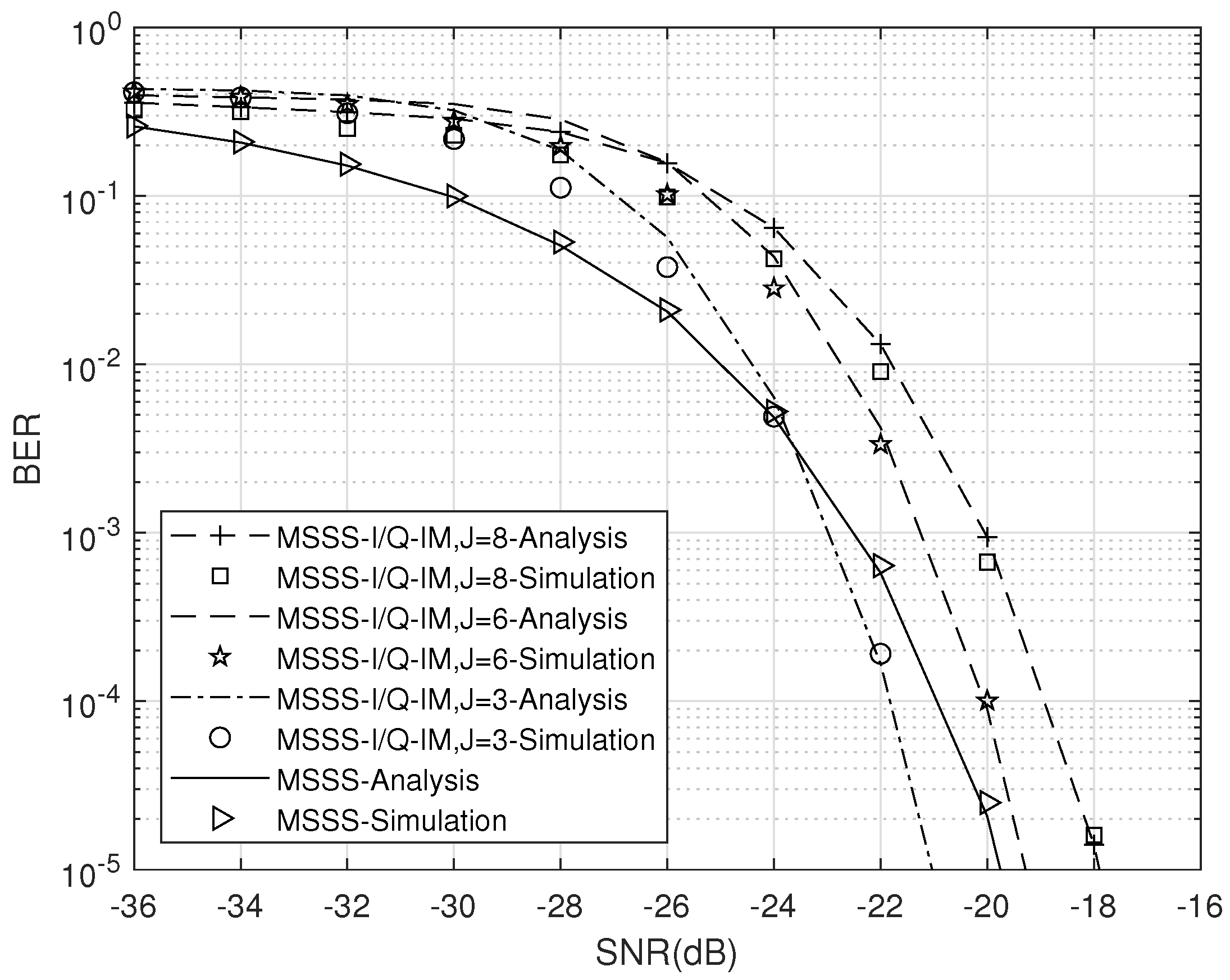
Figure 3 shows the theoretical and simulation results of the MSSS-I/Q-IM and MSSS systems over an AWGN channel. Signal-noise-ratio (SNR) in the figure represents the chip-energy-to-noise-ratio. The shift step size is L + 1 = 101 , and the number of sequences being superimposed is J = 3 , 6 , 8 . In this circumstance, the number of transmitted bits by the two systems within each block is shown in Table 1. As illustrated in the figure, the simulation curves and the theoretical curves are basically fitted, which verifies the correctness of the theoretical BER formula deduced in the previous section. According to Table 1, when J = 3 , the two systems transmit the same number of bits within a spreading sequence duration, which is 18. As shown in Figure 3, compared with the MSSS system, the MSSS-I/Q-IM system can obtain an SNR gain of about 1dB at a BER level of 10 5 . When J = 6 , the data rate of the proposed system exceeds 1 / 3 of that of the MSSS system, and the BER gradually approaches that of the MSSS system with the increasing of SNR.

4.2. BER Performance over a UWA Channel

In this section, the data of the MSSS-I/Q-IM system are modulated on the carrier for simulation experiment, and the BER performance is analyzed by changing various parameters of the system according to different UWA channels. The experiment is carried out on the Watermark 1.0 simulation platform [18].
Two kinds of UWA channels are adopted in the simulation experiment. The first channel was measured in a shallow sea of Oslofjorden, with a fixed single source and a fixed single hydrophone. The second channel was measured on a Shelf in Norway, and the transmitter and receiver were also fixed during the test. The channel impulse response (CSI) of the two channels are shown in Figure 4. The left figure characterizes the Fjord channel, whose delay profile decays quickly, and a cluster of discrete path arrivals is observed between 50 ms and 80 ms, however, these paths only carry a small fraction of the total energy. The stable channel paths carry about 80 % of received signal energy. It is a benign channel on the whole. In contrast, the Shelf channel has a larger Doppler shift.
In the Monte Carlo simulation for the two UWA channels, the sampling rate is 100 kHz, the carrier frequency is 14 kHz, the bandwidth is 8 kHz, the cyclic prefix length is set as 101 chips, and quadrature phase shift keying (QPSK) modulation is adopted.
Table 2 compares the effective bit rate of the MSSS-I/Q-IM and MSSS systems when taking different superposition sequence numbers J, and the signal duration in the simulation is 7.868 s. It can be seen from the table that when J = 3 , the effective bit rate of the two systems are consistent. With the increasing of J, the communication rate of the MSSS-I/Q-IM system increases continuously.
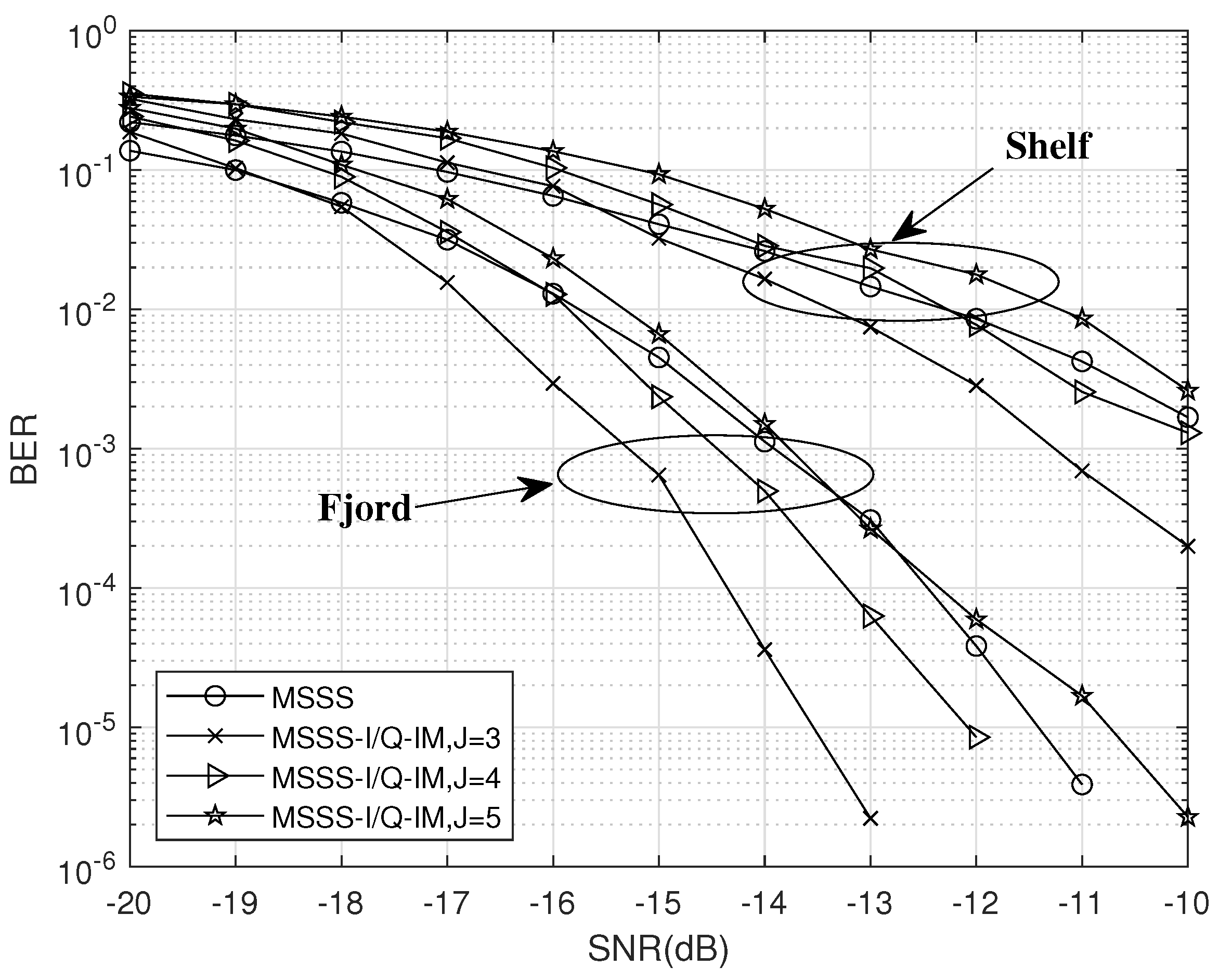
Figure 5 analyzes the influence of parameter J on the BER performance of the systems under the two UWA channels. The length of spreading sequence M = 1023 , and the cyclic shift step size L + 1 = 101 chips. From the overall trend of the curves, the BER over the Fjord channel is better than that over the Shelf channel. When J = 4 , compared with the MSSS system, the MSSS-I/Q-IM system has been able to achieve better BER performance in both UWA channels. In addition, the BER performance gain is larger over the Fjord channel, which means that with the increasing of channel complexity, the performance advantage that the MSSS-I/Q-IM system achieved will decrease. However, according to the influence of J on the BER performance, it indicates that the MSSS-I/Q-IM system has more flexibility.
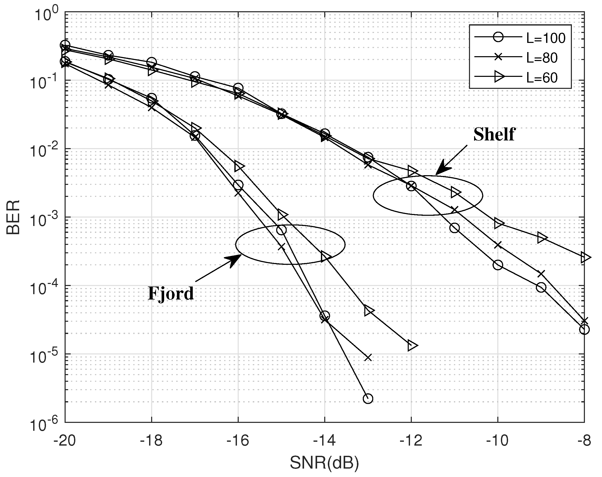
Figure 6 shows the effect of different cyclic shift step sizes on the BER performance of the proposed system. Other parameters are set to M = 1023 and J = 3 . In the simulation, the cyclic prefix length is set to 100, and under different L values, the effective bit rates of the MSSS-I/Q-IM system are the same, at 228.77 bit/s. As shown in the figure, there is a gap in the BER performance under different shift step sizes. Comparing the BER curves when L = 100 and L = 80 over the two UWA channels, the difference between them is small. However, for L = 60 , the BER performance drops significantly. The reason is that when the shift step size is too small, the inter-symbol interference (ISI) of the superimposed sequences is greatly increased. On the other side, when the shift step size is too large, the accuracy of the channel estimation will be reduced by the influence of L. Therefore, the shift step size not only affects the BER performance, but also affects the data rate.

4.3. Water Pool Experiments

In order to verify the practical feasibility of the MSSS-I/Q-IM system, this subsection carried out pool experiments. The inner wall of the pool is smooth, and the size is small. Compared with the marine environment, the multipath effect is more severe, but there is no influence of environmental noise and it is almost time-invariant. Table 3 shows the parameters of the pool experiments.
Through the correlation calculation of the synchronization signal, the CIRs of the channel can be estimated. In the experiment, information blocks with different parameter conditions are concatenated together to form a data packet for transmission. In addition, a synchronization signal is added before each block to estimate the CIRs. Figure 7 shows the CIRs of a data packet at different times. It can be seen from the figure that the channel has a weak variability with time and a large number of multipaths.
In the experiments, due to the use of the attenuator, the amplitude of the signal can be adjusted flexibly. Figure 8 shows the waveform of the received signal for a data packet under different attenuation factors; the attenuation factors are 10, 20, and 50.
Table 4 shows the BER comparison of the MSSS and MSSS-I/Q-IM systems with different parameter J under different attenuation factors. With the continuous increasing of the attenuation degree, the number of bit errors increases. This is because the signal amplitude is continuously reduced, and the interference caused by noise becomes more serious, which affects the correct demodulation. When J = 2 , the BER of the MSSS-I/Q-IM system is slightly higher than that of the MSSS system, and when J = 1 , the BER performance of the MSSS system is much improved. This shows that the MSSS-I/Q-IM system can adjust the BER performance by changing the number of superimposed sequences over a UWA channel and realize the trade-off between the communication rate and the BER performance.
Table 5 shows the effect of the shift step size on the BER of the MSSS-I/Q-IM system. Other parameters of the system are set as M = 1023 , J m a x = 5 , and J = 2 , so the communication rates with different L are the same. It can be found that, compared with other values, the system has the best BER performance for L = 200 . The bit errors do not appear until the attenuation factor is 50 for L = 200 . For other values, the bit error already exists when the attenuation factor is 20. Moreover, by comparing the BER when L = 150 and L = 100 , it is noted that the larger the L is, the better the BER performance is, which indicates that selecting an appropriate shift step is conducive to improving the reliability of the system.
Table 6 shows the effect of the spreading factor M on the BER of the MSSS-I/Q-IM system. According to the table, it is obvious that the larger the spreading factor is, the lower the BER is. However, the duration of data transmission with M = 511 is shorter, and the transmission rate is nearly twice that in the case of M = 1023 . Therefore, in practical application, the change of the spreading factor can affect the BER performance remarkably. The shorter spreading code can greatly improve the communication rate, but it slightly sacrifices the reliability.

5. Conclusions

Aiming at the problem of low data rate of underwater acoustic spread-spectrum communication systems, this paper proposed an in-phase/quadrature index modulation-aided multiple sequences spread-spectrum (MSSS-I/Q-IM) system. By adding in-phase/quadrature index modulation, the MSSS system obtains a new dimension for conveying index bits, so the spectral efficiency and data rate of the system are improved. We also derived the theoretical BER of the MSSS-I/Q-IM system over an AWGN channel and verified it through simulations. Then, in order to verify the feasibility of the MSSS-I/Q-IM system for a UWA channel, the simulations over UWA channels and the pool experiments were carried out. The results have proved that the proposed system can achieve higher data rate and better BER performance in UWA channels by adjusting system key parameters, such as J. In other words, the proposed system has shown a good trade-off between data rate and BER performance. In the future, we will further investigate the theoretical performance of the proposed scheme over multipath fading channels and UWA channels. In addition, to verify the robustness of the proposed scheme in complex environments, we will carry out some field experiments in sea or lake scenarios.

Author Contributions

Conceptualization, Y.W., L.Q. and W.X.; methodology, Y.W., L.Q., W.X. and D.W.; software, L.Q., W.X. and D.W.; validation, W.X.; formal analysis, Y.W., L.Q. and W.X.; writing—original draft preparation, Y.W., L.Q. and L.W.; writing—review and editing, Y.W., L.Q., W.X. and L.W.; visualization, Y.W.; supervision, W.X.; project administration, L.W.; funding acquisition, D.W. and W.X. All authors have read and agreed to the published version of the manuscript.

Funding

This work was supported in part by the Key Laboratory of Southeast Coast Marine Information Intelligent Perception and Application, Ministry of Natural Resources (MNR), No. KFJJ20220201. This work was supported in part by the National Natural Science Foundation of China under Grant 62271427 and 61871337.

Institutional Review Board Statement

Not applicable.

Informed Consent Statement

Not applicable.

Data Availability Statement

Not applicable.

Conflicts of Interest

The authors declare no conflict of interest.

References

  1. Farr, N.; Bowen, A.; Ware, J.; Pontbriand, C.; Tivey, M. An integrated, underwater optical/acoustic communications system. In Proceedings of the OCEANS’10 IEEE SYDNEY, Sydney, NSW, Australia, 24–27 May 2010; pp. 1–6. [Google Scholar]
  2. Brekhovskikh, L.; Lysanov, Y.P. Fundamentals of Ocean Acoustics; Acoustical Society of America; Springer: Berlin/Heidelberg, Germany, 2004. [Google Scholar]
  3. Diamant, R.; Lampe, L. Low probability of detection for underwater acoustic communication: A review. IEEE Access. 2018, 6, 19099–19112. [Google Scholar] [CrossRef]
  4. Zhou, Y.; Tong, F. Channel estimation based equalizer for underwater acoustic multiple-inputmultiple-output communication. IEEE Access. 2019, 7, 79005–79016. [Google Scholar] [CrossRef]
  5. Dillard, G.M.; Reuter, M.; Zeidler, J.; Zeidler, B. Cyclic code shift keying: A low probability of intercept communication technique. IEEE Trans. Aerosp. Electron. Syst. 2003, 39, 786–798. [Google Scholar] [CrossRef] [Green Version]
  6. He, C.B.; Huang, J.G.; Han, J.; Zhang, Q.F. Cyclic shift keying spread spectrum underwater acoustic communication. Acta Phys. Sinica. 2009, 58, 8379–8385. [Google Scholar]
  7. He, C.; Zhang, Q.; Huang, J. Passive time reversal communication with cyclic shift keying over underwater acoustic channels. Appl. Acoust. 2015, 96, 132–138. [Google Scholar] [CrossRef]
  8. Yang, Y.U.; Feng, Z.H.O.U.; Gang, Q.I.A.O.; Donghu, N.I.E. Orthogonal M-ary code shift keying spread spectrum underwater acoustic communication. Chin. J. Acoust. 2014, 33, 279. [Google Scholar]
  9. Zhou, F.; Liu, B.; Nie, D.; Yang, G.; Zhang, W.; Ma, D. M-ary cyclic shift keying spread spectrum underwater acoustic communications based on virtual time-reversal mirror. Sensors 2019, 19, 3577. [Google Scholar] [CrossRef] [PubMed] [Green Version]
  10. Lu, Q.; Hu, X.; Wang, D.; Zhou, S. Parallel combinatory multicarrier modulation in underwater acoustic communications. IET Commun. 2017, 11, 1331–1337. [Google Scholar] [CrossRef]
  11. Qu, F.; Qin, X.; Yang, L.; Yang, T.C. Spread-spectrum method using multiple sequences for underwater acoustic communications. IEEE J. Ocean. Eng. 2017, 43, 1215–1226. [Google Scholar] [CrossRef]
  12. Ishikawa, N.; Sugiura, S.; Hanzo, L. 50 years of permutation, spatial and index modulation: From classic rf to visible light communications and data storage. IEEE Commun. Surv. Tutor. 2018, 20, 1905–1938. [Google Scholar] [CrossRef] [Green Version]
  13. Sugiura, S.; Ishihara, T.; Nakao, M. State-of-the-art design of index modulation in the space, time, and frequency domains: Benefits and fundamental limitations. IEEE Access 2017, 5, 21774–21790. [Google Scholar] [CrossRef]
  14. Kaddoum, G.; Nijsure, Y.; Tran, H. Generalized code index modulation technique for high-data-rate communication systems. IEEE Trans. Veh. Technol. 2015, 65, 7000–7009. [Google Scholar] [CrossRef] [Green Version]
  15. Wen, M.; Cheng, X.; Yang, L.; Li, Y.; Cheng, X.; Ji, F. Index modulated OFDM for underwater acoustic communications. IEEE Commun. Mag. 2015, 54, 132–137. [Google Scholar] [CrossRef]
  16. Qasem, Z.A.H.; Wang, J.; Leftah, H.A.; Sun, H.; Hong, S.; Qi, J.; Esmaiel, H. Real signal DHT-OFDM with index modulation for underwater acoustic communication. IEEE J. Ocean. Eng. 2023, 48, 246–259. [Google Scholar] [CrossRef]
  17. Quan, L.; Xu, W.; Wang, D.; Wang, L. A multiple sequences spread-spectrum system with in-phase/quadrature index modulation for underwater acoustic communications. In Proceedings of the 15th International Symposium on Medical Information and Communication Technology (ISMICT), Xiamen, China, 14–16 April 2021; pp. 29–34. [Google Scholar]
  18. van Walree, P.A.; Socheleau, F.X.; Otnes, R.; Jenserud, T. The watermark benchmark for underwater acoustic modulation schemes. IEEE J. Ocean. Eng. 2017, 42, 1007–1018. [Google Scholar] [CrossRef] [Green Version]
  19. Başar, E.; Aygölü, Ü.; Panayırcı, E.; Poor, H.V. Orthogonal frequency division multiplexing with index modulation. IEEE Trans. Signal Process. 2013, 61, 5536–5549. [Google Scholar] [CrossRef]
  20. Cai, X.; Xu, W.; Wang, L.; Kolumbán, G. Multicarrier m-ary orthogonal chaotic vector shift keying with index modulation for high data rate transmission. IEEE Trans. Commun. 2019, 68, 974–986. [Google Scholar] [CrossRef]
Figure 1. The block diagram of the MSSS-I/Q-IM transmitter.
Electronics 12 02919 g001
Figure 2. The block diagram of the MSSS-I/Q-IM receiver.
Electronics 12 02919 g002
Figure 3. BER performance of the two systems with M = 1023 , L = 100 , and J = 8 , 6 , 3 over an AWGN channel.
Electronics 12 02919 g003
Figure 4. The CIRs of the Fjord and Shelf channels.
Electronics 12 02919 g004
Figure 5. BER performances of the two systems with J = 5 , 4 , 3 over a UWA channel.
Electronics 12 02919 g005
Figure 6. Influence of parameter L on BER performance of the MSSS-I/Q-IM system over UWA channels.
Electronics 12 02919 g006
Figure 7. The CIRs measured in the pool experiments.
Electronics 12 02919 g007
Figure 8. Received signal with different attenuation factors.
Electronics 12 02919 g008
Table 1. The number of transmitted bits by the two systems within a spreading sequence duration.
MSSSMSSS-I/Q-IM
18 J = 8 J = 6 J = 3
222418
Table 2. Comparison of effective bit rates of the two systems.
MSSSMSSS-I/Q-IM
228.77 bit/s J = 3 228.77 bit/s
J = 4 254.19 bit/s
J = 5 279.61 bit/s
Table 3. Parameters of water pool experiments.
ParametersValue
Distance10 m
Sample Rate100 kHz
Carrier Frequency25 kHz
Synchronization SignalLFM Signal
Bandwidth6 kHz
Table 4. BER comparison between the two systems.
Attenuation FactorEstimated SNRMSSSMSSS-I/Q-IM
J = 3J = 2J = 1
10−10.620000
20−11.610000
50−14.830.06500.16100.07720.0027
100−20.550.25920.35600.31660.1347
Table 5. Influence of parameter L on the BER of the MSS-I/Q-IM system.
Attenuation FactorEstimated SNRL = 200L = 150L = 100
20−8.6700.07120.0101
25−9.3600.15660.0652
100/3−11.2400.16100.0572
50−12.750.01210.20830.1092
Table 6. Influence of parameter M on the BER of the MSSS-I/Q-IM system.
Attenuation FactorEstimated SNRM = 1023M = 1023
50−6.010.01030.1340
100−9.970.34050.4787
125−12.370.34540.4183
Disclaimer/Publisher’s Note: The statements, opinions and data contained in all publications are solely those of the individual author(s) and contributor(s) and not of MDPI and/or the editor(s). MDPI and/or the editor(s) disclaim responsibility for any injury to people or property resulting from any ideas, methods, instructions or products referred to in the content.