Communication

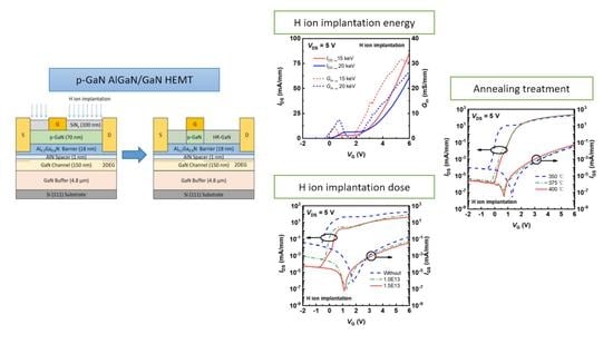
p-GaN Selective Passivation via H Ion Implantation to Obtain a p-GaN Gate Normally off AlGaN/GaN HEMT

1
School of Materials Science and Engineering, Nanjing University of Science and Technology, Nanjing 210094, China
2
Nanofabrication Facility, Suzhou Institute of Nano-Tech and Nano-Bionics, Chinese Academy of Sciences, Suzhou 215123, China
3
Guangdong Institute of Semiconductor Micro-NANO Manufacturing Technology, Foshan 528200, China
4
Suzhou Powerhouse Electronics Co., Ltd., Suzhou 215123, China
*
Authors to whom correspondence should be addressed.
Electronics 2023, 12(6), 1424; https://doi.org/10.3390/electronics12061424
Submission received: 15 February 2023 / Revised: 10 March 2023 / Accepted: 14 March 2023 / Published: 16 March 2023
(This article belongs to the Special Issue Nitride Semiconductor Devices and Applications)

Abstract

:
A dependable and robust technique for nanomachining is ion implantation. In this work, hydrogen (H) ion implantation was used, for the first time, to passivate p-GaN, except for the gate area, in order to create a normally off p-GaN/AlGaN/GaN high-electron-mobility transistor (HEMT). Ion implantation passivation reduces H ion diffusion in p-GaN, allowing it to withstand temperatures above 350 °C. Through experiments and analyses, the H ion implantation energy and dosage required to passivate p-GaN, by generating Mg-H neutral complexes, were determined to be 20 keV and 1.5 × 1013 cm−2, respectively. After conducting annealing procedures at various temperatures, we discovered that 400 °C was the ideal temperature to effectively obtain a normally off p-GaN HEMT. A threshold voltage of 0.8 V was achievable. The p-GaN HEMT also had a breakdown voltage of 642 V at a gate voltage of 0 V, maximum transconductance of 57.7 mS/mm, an on/off current ratio of 108, an on-resistance of 8.4 mm, and a maximum drain current of 240.0 mA/mm at a gate voltage of 6 V after being annealed at 400 °C.

Graphical Abstract

1. Introduction

Due to its wide bandgap and high electron mobility, AlGaN/GaN high-electron-mobility transistors (HEMTs) are advantageous for power electronics [1,2,3,4]. The conventional HEMT is a normally on device [3,4,5,6]. However, a normally off device is more secure [7,8,9,10]. The p-GaN gate [11,12,13] is one of the most common methods of preparing a normally off HEMT. In some studies, etching p-GaN [14,15] and passivating p-GaN using hydrogen plasma [16,17] are effective techniques to realize the p-GaN gate via the selective shedding of p-GaN. Nevertheless, etching can easily cause interface damage. Additionally, hydrogen will diffuse at high temperatures after hydrogen plasma treatment. There are still some difficulties associated with the stability and controllability of using these techniques in practice [18].
In this work, to obtain a p-GaN gate, H ion implantation, which is a reliable and stable method, was conducted to selectively shed the p-GaN layer. The Mg acceptors in p-GaN can form Mg-H neutral complexes [16,17] via H ion implantation. Then, the p-GaN becomes a high-resistance GaN. H ion implantation also can be applied to introduce spin carriers or p-GaN-based spintronics [19,20,21]. The H concentration is accumulated on the surface after H plasma treatment. H is easily diffused into the p-GaN gate. When exposed to high temperatures, the device will fail [16]. Due to the modicum of H ion on the surface due to ion implantation passivation, p-GaN can withstand temperatures above 350 °C. After conducting our experiments and analyses, the factors of H ion implantation containing the implantation energy, ion dose, and annealing conditions to passivate p-GaN were ascertained. The p-GaN HEMT with H ion implantation successfully achieved normally off operation. A maximum drain current of 240 mA/mm was found to be larger than that of p-GaN gate HEMTs using selective plasma etching and metallization technologies [12].

2. Materials and Methods

The p-GaN/AlGaN/GaN heterojunction was grown via metal-organic chemical vapor deposition on a 6-inch Si substrate. As shown in Figure 1a, the epitaxy material was composed of a GaN buffer layer, a GaN channel layer, an AlN space layer, an Al0.2Ga0.8N barrier layer, and a p-GaN cap layer with 3 × 1019 cm−3 Mg doping. The device was isolated first. Before source (S) and drain (D) deposition, the p-GaN was graphically etched using inductively coupled plasma. Then, Ti/Al/Ni/Au metals were deposited on the source and drain regions, and ohmic contacts were formed after annealing at 875 ℃ for 30 s. Additionally, Ni/Au metals were evaporated at the gate electrode (G) [16,17]. The devices were coated with silicon nitride (SiNx) as the sacrificial layer. After that, the p-GaN cap layer was deactivated via H ion implantation, except for the gate regions, as shown in Figure 1a. Finally, the SiNx was removed via reactive ion etching, and the p-GaN HEMT shown in Figure 1b was prepared. Figure 1c displays an optical image of the p-GaN HEMT.

3. Results and Discussion

Firstly, the H ion implantation energy was determined. In this work, 15 keV and 20 keV implantation energies were applied to p-GaN HEMTs. Figure 2a shows the transfer curves of devices with H ion implantation energies of 15 keV and 20 keV, without annealing. The drain current (IDS) of the device with an implantation energy of 15 keV is 85.5 mA/mm at a gate voltage (VG) of 6 V, which is 38% more than that with a H ion implantation energy of 20 keV. Additionally, the values of peak transconductance (Gm) are 31.7 mS/mm and 26.7 mS/mm for p-GaN HEMTs with H ion implantation energies of 15 keV and 20 keV, respectively. The average threshold voltages (VTh) of the p-GaN HEMT, defined as VG at IDS = 10 μA/mm, are −0.4 V and −0.2 V after H ion implantation of 15 keV and 20 keV. Additionally, the gate leakage at the negative bias of devices with H ion implantation energies of 15 keV and 20 keV are shown in Figure 2c. The gate leakage current (IG) of the p-GaN HEMT with a H ion implantation energy of 15 keV is 68% lower than that with a H ion implantation energy of 20 keV at VG = −8 V. Therefore, 15 keV is more suitable than 20 keV as a H ion implantation energy in the p-GaN HEMT.
Thus, this H ion implantation dose is indispensable for passivating p-GaN completely. During simulation, the H ion dose is about 1.0 × 1013 cm−2 in this work. To further determine the dose in p-GaN HEMTs, H ion doses of 1.0 × 1013 cm−2 and 1.5 × 1013 cm−2 were experimented with. Figure 3a contrasts the transfer characteristics at the log scale of devices without H ion implantation, and with H ion implantation doses of 1.0 × 1013 cm−2 and 1.5 × 1013 cm−2, without annealing. Before H ion implantation, the device is a normally on HEMT. The average value of VTh is −0.2 V after 1.0 × 1013 cm−2 H ion implantation. This means a H ion implantation dose of 1.0 × 1013 cm−2 cannot passivate p-GaN entirely. Fortunately, as shown in Figure 3b, the average value of VTh is 0.1 V in the p-GaN HEMT after a H ion implantation dose of 1.5 × 1013 cm−2. This indicates that after a H ion implantation dose of 1.5 × 1013 cm−2, the device is a normally off HEMT. Figure 3c shows the output characteristics at VG = 6 V of p-GaN HEMTs without H ion implantation, and with H ion implantation doses of 1.0 × 1013 cm−2 and 1.5 × 1013 cm−2. The maximum drain current of the device at VG = 6 V with a H ion implantation dose of 1.5 × 1013 cm−2 is 53.7 mA/mm, which is less than that with a dose of 1.0 × 1013 cm−2 (81.1 mA/mm) and without H ion implantation (228.9 mA/mm).
To passivate p-GaN completely, sufficient dosage and energy are required. Nevertheless, the lattice damage increases as the energy and dose of ion implantation increase, resulting in an increase in the device’s on-resistance and a decrease in the saturation current. To obtain a high saturation current, lattice damage must be repaired through high-temperature annealing. Three temperatures (350, 375, and 400 °C) were adopted in this work. As shown in Figure 4a, the transfer characteristics of p-GaN HEMTs during H ion implantation, after annealing at three temperatures, can be compared. After annealing at 350, 375, and 400 °C, the average values of the threshold voltages in Figure 4b are 0 V, 0.6 V, and 0.7 V, respectively. In Figure 4c, the gate leakage values of p-GaN HEMTs with H ion implantation at VG = −8 V, after annealing at 350, 375, and 400 °C, are 1.2 × 10⁻⁴ mA/mm, 6.3 × 10⁻⁶ mA/mm, and 1.3 × 10⁻⁶ mA/mm, respectively. Compared with the three annealing treatments, 400 °C is the optimal temperature.
Finally, the p-GaN HEMT obtained via H ion implantation with energy of 15 keV and a dose of 1.5 × 1013 cm−2, after annealing at 400 °C, was measured. The on/off current ratio is ~106, as shown in Figure 4a. From the transfer curve in Figure 5a, it can be seen that the value of Gm is 57.7 mS/mm. The maximum drain current at VG = 6 V is 240.0 mA/mm, as shown in Figure 5b. Additionally, the on-resistance (RON) is calculated to be 8.4 Ω·mm. As shown in Figure 5c, the breakdown voltage is 642 V at VG = 0 V.

4. Conclusions

In summary, we investigated the H ion implantation of a p-GaN HEMT to passivate p-GaN, except for the gate region. The H ion implantation energy was 15 keV. Additionally, to passivate p-GaN completely, the H ion implantation dose was 1.5 × 1013 cm−2. Annealing treatment was implemented after H ion implantation to improve the crystal damage caused by implantation. Compared with 350 and 375 °C, 400 °C was an ideal temperature for annealing treatment in this work. After annealing at 400 °C, the normally off device with H ion implantation succeeded, with a threshold voltage of 0.8 V and an on/off current ratio of 108.

Author Contributions

Conceptualization, G.Y. and B.Z. (Baoshun Zhang); methodology, X.D. and X.Y.; software, X.Y.; validation, X.Y., X.D., B.Z. (Bingliang Zhang), Z.D. and G.Y.; formal analysis, X.D. and X.Y.; investigation, X.D. and X.Y.; resources, X.D. and X.Y.; data curation, X.D. and X.Y.; writing—original draft preparation, X.D.; writing—review and editing, X.Y. and G.Y.; visualization, X.D.; supervision, Z.Z., X.Z. and B.Z. (Baoshun Zhang); project administration, Z.Z. T.J., X.Z. and B.Z. (Baoshun Zhang); funding acquisition, T.J., X.Z. and B.Z. (Baoshun Zhang). X.D. and X.Y. have contributed equally to this work. All authors have read and agreed to the published version of the manuscript.

Funding

This research was funded by the Suzhou science and technology foundation (SYG202027), the Youth Innovation Promotion Association of the Chinese Academy of Sciences (Grant No.2020321), and the National Natural Science Foundation of China (Grant No.92163204).

Data Availability Statement

The data presented in this study are available upon request from the corresponding author.

Acknowledgments

The authors would like to thank the Nanofabrication Facility, Vacuum Interconnected Nanotech Workstation (NANO-X) of the Suzhou Institute of Nano-Tech and Nano-Bionics for their technical support.

Conflicts of Interest

The authors declare no conflict of interest.

References

  1. Ambacher, O.; Foutz, B.; Smart, J.; Shealy, J.; Weimann, N.G.; Chu, K.; Murphy, M.; Sierakowski, A.J.; Schaff, W.J.; Eastman, L.F.; et al. Two dimensional electron gases induced by spontaneous and piezoelectric polarization in undoped and doped AlGaN/GaN heterostructures. J. Appl. Phys. 2000, 87, 334–344. [Google Scholar] [CrossRef]
  2. Xing, H.; Keller, S.; Wu, Y.-F.; McCarthy, L.; Smorchkova, I.P.; Buttari, D.; Coffie, R.; Green, D.S.; Parish, G.; Heikman, S.; et al. Gallium nitride based transistors. J. Phys. Condens. Matter. 2001, 13, 7139. [Google Scholar] [CrossRef]
  3. Mishra, U.K.; Parikh, P.; Wu, Y.-F. AlGaN/GaN HEMTs-an overview of device operation and applications. Proc. IEEE 2002, 90, 1022–1031. [Google Scholar] [CrossRef] [Green Version]
  4. Hudgins, J.L.; Simin, G.S.; Santi, E.; Khan, M.A. An assessment of wide bandgap semiconductors for power devices. IEEE Trans. Power Electron. 2003, 18, 907–914. [Google Scholar] [CrossRef] [Green Version]
  5. Miyoshi, M.; Egawa, T.; Ishikawa, H. Structural characterization of strained AlGaN layers in different Al content AlGaN/GaN heterostructures and its effect on two-dimensional electron transport properties. J. Vac. Sci. Technol. B 2005, 23, 1527–1531. [Google Scholar] [CrossRef]
  6. Effect of Source Field Plate Cracks on the Electrical Performance of AlGaN/GaN HEMT Devices. Crystals 2022, 12, 1195. [CrossRef]
  7. Khan, M.A.; Chen, Q.; Sun, C.; Yang, J.; Blasingame, M.; Shur, M.; Park, H. Enhancement and depletion mode GaN/AlGaN heterostructure field effect transistors. Appl. Phys. Lett. 1996, 68, 514–516. [Google Scholar] [CrossRef]
  8. Cai, Y.; Zhou, Y.; Chen, K.J.; Lau, K.M. High-performance enhancement-mode AlGaN/GaN HEMTs using fluoride-based plasma treatment. IEEE Electron Device Lett. 2005, 26, 435–437. [Google Scholar]
  9. Cai, Y.; Zhou, Y.; Lau, K.M.; Chen, K.J. Control of threshold voltage of AlGaN/GaN HEMTs by fluoride-based plasma treatment: From depletion mode to enhancement mode. IEEE Trans. Electron Devices 2006, 53, 2207–2215. [Google Scholar] [CrossRef]
  10. Nanjo, T.; Takeuchi, M.; Suita, M.; Oishi, T.; Abe, Y.; Tokuda, Y.; Aoyagi, Y. Remarkable breakdown voltage enhancement in AlGaN channel high electron mobility transistors. Appl. Phys. Lett. 2008, 92, 263502. [Google Scholar] [CrossRef]
  11. Meneghini, M.; Hilt, O.; Wuerfl, J.; Meneghesso, G. Technology and reliability of normally-off GaN HEMTs with p-type gate. Energies 2017, 10, 153. [Google Scholar] [CrossRef] [Green Version]
  12. Greco, G.; Iucolano, F.; Roccaforte, F. Review of technology for normally-off HEMTs with p-GaN gate. Mater. Sci. Semicond. Process. 2018, 78, 96–106. [Google Scholar] [CrossRef]
  13. Roccaforte, F.; Greco, G.; Fiorenza, P.; Iucolano, F. An overview of normally-off GaN-based high electron mobility transistors. Materials 2019, 12, 1599. [Google Scholar] [CrossRef] [PubMed] [Green Version]
  14. Hu, Q.; Li, S.; Li, T.; Wang, X.; Li, X.; Wu, Y. Channel Engineering of Normally-OFF AlGaN/GaN MOS-HEMTs by Atomic Layer Etching and HighHigh- κ Dielectric. IEEE Electron Device Lett. 2018, 39, 1377–1380. [Google Scholar] [CrossRef]
  15. Chang, Y.-C.; Ho, Y.-L.; Huang, T.-Y.; Huang, D.-W.; Wu, C.-H. Investigation of Normally-Off p-GaN/AlGaN/GaN HEMTs Using a Self-Terminating Etching Technique with Multi-Finger Architecture Modulation for High Power Application. Micromachines 2021, 12, 432. [Google Scholar] [CrossRef] [PubMed]
  16. Hao, R.; Fu, K.; Yu, G.; Li, W.; Yuan, J.; Song, L.; Zhang, Z.; Sun, S.; Li, X.; Cai, Y.; et al. Normally-off p-GaN/AlGaN/GaN high electron mobility transistors using hydrogen plasma treatment. Appl. Phys. Lett. 2016, 109, 152106. [Google Scholar] [CrossRef]
  17. Xu, N.; Hao, R.; Chen, F.; Zhang, X.; Zhang, H.; Zhang, P.; Ding, X.; Song, L.; Yu, G.; Cheng, K. Gate leakage mechanisms in normally off p-GaN/AlGaN/GaN high electron mobility transistors. Appl. Phys. Lett. 2018, 113, 152104. [Google Scholar] [CrossRef]
  18. Sayadi, L.; Iannaccone, G.; Sicre, S.; Häberlen, O.; Curatola, G. Threshold voltage instability in p-GaN gate AlGaN/GaN HFETs. IEEE Trans. Electron Devices 2018, 65, 2454–2460. [Google Scholar] [CrossRef]
  19. Saravade, V.; Ghods, A.; Woode, A.P.; Zhou, C.; Ferguson, I. GaN-based Room Temperature Spintronics for Next Generation Low Power Consumption Electronic Devices. In Proceedings of the 2019 IEEE 16th International Conference on Smart Cities: Improving Quality of Life Using ICT & IoT and AI (HONET-ICT), Charlotte, NC, USA, 6–9 October 2019; pp. 203–204. [Google Scholar]
  20. Cho, K.S.; Huang, T.-Y.; Wang, H.-S.; Lin, M.-G.; Chen, T.-M.; Liang, C.-T.; Chen, Y.F.; Lo, I. Zero-field spin splitting in modulation-doped AlxGa1−xN/GaN two-dimensional electron systems. Appl. Phys. Lett. 2005, 86, 222102. [Google Scholar] [CrossRef]
  21. Lin, D.; Kang, W.; Wu, Q.; Song, A.; Wu, X.; Liu, G.; Wu, J.; Wu, Y.; Li, X.; Wu, Z.; et al. High-Efcient Spin Injection in GaN at Room Temperature Through A Van der Waals Tunnelling Barrier. Nanoscale Res. Lett. 2022, 17, 74. [Google Scholar] [CrossRef] [PubMed]
Figure 1. Schematic diagram of p-GaN HEMTs: (a) H ion implantation; (b) p-GaN selective passivation; (c) optical image of the p-GaN HEMT.
Electronics 12 01424 g001
Figure 2. (a) Transfer characteristics; (b) average values and errors of threshold voltages; (c) gate leakage curves at the negative bias of p-GaN HEMTs with H ion implantation energies of 15 keV and 20 keV, without annealing.
Electronics 12 01424 g002
Figure 3. (a) Transfer characteristics in log scale; (b) average values and errors of threshold voltages; (c) output characteristics at VG = 6 V of p-GaN HEMTs without H ion implantation and with H ion implantation doses of 1.0 × 1013 cm−2 and 1.5 × 1013 cm−2, without annealing.
Electronics 12 01424 g003
Figure 4. (a) Transfer characteristics at log scale; (b) average values and errors of threshold voltages; (c) gate leakage characteristics at the negative bias of p-GaN HEMTs obtained via H ion implantation, after annealing at 350, 375, and 400 °C.
Electronics 12 01424 g004
Figure 5. (a) Transfer characteristic; (b) output characteristic; (c) breakdown curve of the p-GaN HEMT obtained via H ion implantation with energy of 15 keV and a dose of 1.5 × 1013 cm−2, after annealing at 400 °C.
Electronics 12 01424 g005
Disclaimer/Publisher’s Note: The statements, opinions and data contained in all publications are solely those of the individual author(s) and contributor(s) and not of MDPI and/or the editor(s). MDPI and/or the editor(s) disclaim responsibility for any injury to people or property resulting from any ideas, methods, instructions or products referred to in the content.

