Communication

Design of Parameter-Optimized Spiral Arrays with Ultra-Wideband Grating Lobe Suppression

1
Institute of Electromagnetics and Acoustics, Xiamen University, Xiamen 361000, China
2
Yangtze Delta Region Institute (Quzhou), University of Electronic Science and Technology of China, Quzhou 323000, China
3
School of Electronic Science and Engineering, University of Electronic Science and Technology of China, Chengdu 610000, China
*
Author to whom correspondence should be addressed.
Electronics 2023, 12(7), 1664; https://doi.org/10.3390/electronics12071664
Submission received: 21 February 2023 / Revised: 23 March 2023 / Accepted: 29 March 2023 / Published: 31 March 2023

Abstract

:
An effective method is presented to design the layout of spiral array with ultra-wideband (UWB) grating lobe suppression. In this method, the general array factor expression of spiral array is formulated. Then, the synthesis problem of spiral array layout is converted to an optimization problem of three geometric parameters: s, r and Δ ϕ . These parameters can determine the exact position of each element. The optimization problem is solved by particle swarm optimization (PSO) algorithm where the constraints of element spacing and array aperture are introduced. For different-sized spiral arrays, there are always only three variables that need to be optimized in the PSO algorithm, which allows the proposed method to handle the layout design of large-scale spiral arrays with UWB grating lobe suppression. Two examples with different synthesis requirements are conducted to verify the effectiveness and advantages of the proposed method.

1. Introduction

Ultra-wideband (UWB) antenna arrays have been widely used in many applications such as radar imaging system, high-speed data transmission and radio astronomy [1,2]. Compared with narrowband arrays, UWB arrays generally require to have grating lobe suppression performance in a wide frequency band instead of a single frequency point, which results in UWB array synthesis being much more challenging. For the grating lobe suppression, the existing effective approaches can be summarized into two classes. The first class is for uniformly spaced arrays, and it applies very small inter-element spacing (no more than half a wavelength at highest frequency) so that no grating lobe appears in the visible region [3]. However, this type of approaches usually requires complicated techniques such as tightly-coupled antenna design method to improve radiation efficiency and impedance matching at low frequency band [4]. In addition, it also needs a large amount of elements to fill the array aperture, which can lead to a significant increase in the weight and cost of the array system. The second class is to directly use aperiodic array layouts to avoid the appearance of grating lobes. It is clear that the aperiodic array layout requires fewer elements than the dense array layout used in the first class of approaches. Moreover, in Terahertz applications, the RF components of the antenna array elements are generally of large electrical size, so the aperiodic array layout is more advantageous for practical manufacturing implementation. Considering the cost and difficulty of the hardware design, the second class of approaches is more appropriate for UWB arrays. Then, how to obtain the aperiodic array layouts that meet the desired synthesis requirements becomes a vital issue.
In the last few decades, a variety of methods for designing aperiodic array layouts have been proposed. These methods include analytical method [5], matrix pencil method [6], iterative convex optimization [7], compressive sensing technique [8] and other methods [9,10]. They can achieve satisfactory grating lobe level and sidelobe level for narrowband cases. However, as the working frequency increases, most of them fail to maintain the grating lobe suppression performance. In order to eliminate the grating lobe in UWB cases, some arrays with special geometries are introduced, such as space-filling curve arrays [11], aperiodic tiling arrays [12] and rotation-symmetric arrays [13]. Among them, the space-filling curve array is designed by using the curve consisting of a self-avoiding path that intersects a triangular lattice. The aperiodic tiling array is generated by placing array elements at the locations of the vertices of an aperiodic tiling. The rotation symmetry array is inspired by the aperiodic structures of quasicrystals. However, these special geometric arrays by themselves cannot achieve grating lobe suppression over UWB, and therefore, stochastic optimization methods (such as genetic algorithm in [11,12] and covariance matrix adapation evolutionary algorithm in [13]) are usually needed to refine the element positions so as to further extend the working bandwidth. In such a strategy, the number of variables to be optimized equals the number of elements. Consequently, when considering large-scale arrays, the large number of variables can significantly increase the complexity of the optimization problem, making it so hard to reach the global optimal solution.
The spiral array is another kind of special geometric array, and it has been confirmed to possess satisfactory performance in UWB grating lobe suppression [14,15]. Different from the aforementioned arrays, the layout of spiral array is determined by only three geometric parameters of s, r and Δ ϕ , and therefore, the exact element positions can be easily accessible. By changing the parameter configuration, some classical arrays can be produced, such as Fermat spiral arrays [15] and Archimedean spiral arrays [16]. However, for different synthesis requirements (in terms of bandwidth, element count, element spacing and array aperture), the geometric parameters of the classical arrays remain fixed, which limits the UWB grating lobe suppression effect that could have been achieved. To the best of our knowledge, the optimization of the geometric parameters is very important to improve the array performance, but rarely reported in open literature. This paper will present an effective method to obtain the optimal geometric parameters in the sense of UWB grating suppression. First, we formulate a general expression of spiral arrays. Based on the expression, the layout design of spiral array with UWB grating lobe suppression can be converted to the optimization of s, r and Δ ϕ , which can greatly simplify the synthesis process compared with directly perturbing the element positions, thereby making the layout design for large-scale spiral arrays possible. Then, the optimization problem is solved by particle swarm optimization (PSO) algorithm [17] where the element spacing constraint and array aperture constraint are applied to meet the requirements of antenna size and platform size. To verify the effectiveness of the proposed method, two examples are conducted for different spiral arrays. The comparisons with other UWB array layouts are also presented in these examples.

2. Formulation and Algorithm

2.1. General Spiral Array Model

Consider an arbitrary planar array with N elements allocated on the x o y plane. The position of the nth element can be expressed as x n  =  ρ n cos ϕ n and y n  =  ρ n sin ϕ n , where ρ n is the distance from element position to array geometric center, and ϕ n is the angle deviation from the x axis. Assume that this array works at UWB from f L to f H . When uniform excitation is used, the far-field array factor can be written as
A F ( β , θ , φ ) = n = 0 N exp j β ρ n sin θ cos ( ϕ n φ )
where β = 2 π f / v is the free-space wavenumber, v is the wave propagation velocity, and θ and φ are the elevation and azimuth angles, respectively.
For the periodic array, when the working frequency increases, grating lobes can appear in the visible region, which is undesirable in the UWB application [12]. The aperiodic array is a solution to avoid this problem. The spiral line is a typical aperiodic array geometry where antennas are allocated discretely on the curve [18]. Generally, a spiral line in the polar coordinates can be expressed as
ρ = c ϕ r
where ρ is the polar radius and ϕ is the polar angle. The parameter settings of c and r are related to the intervals between spiral turns. Based on the spiral line equation of (2), a set of spiral array layouts can be derived. By sampling ϕ with ϕ n = n Δ ϕ (where n = 1 , 2 N and Δ ϕ is the polar angle spacing), we have ρ n = c ( n Δ ϕ ) r . Then, with the substitution of s = c ( Δ ϕ ) r , we can get the following parametric equation of the spiral array geometry:
ρ n = s n r ϕ n = n Δ ϕ for n = 1 , 2 N
Clearly, the parameter configuration of s, r and Δ ϕ directly determines the array layout as well as the array characteristics. There are some classical cases such as Fermat spiral arrays [14,15] and Archimedean spiral arrays [16]. In comparison, Fermat spiral arrays show better performance in UWB grating lobe suppression, which has attracted increasing attention [14,15]. The geometric parameters of classical spiral arrays usually remain the same, even for completely different synthesis requirements. For example, Fermat spiral arrays specify s = d min / 5 4 cos Δ ϕ G , r = 1 / 2 and Δ ϕ = Δ ϕ G (where d min is the desired minimum element spacing and Δ ϕ G is the golden angle [15]), which are independent of the array size. The fixed parameter configuration can limit the achievable array performance. By substituting (3) into (1), the general array factor of spiral array can be obtained, that is
A F ( β , θ , φ ; s , r , Δ ϕ ) = n = 0 N exp j β s n r sin θ cos ( n Δ ϕ φ )
This expression correlates the geometric parameters with the array radiation features. Base on (4), it is natural to consider optimizing the parameters to achieve a better array layout.

2.2. Parameter-Optimized Spiral Array by PSO Algorithm

The optimization goal can be described as finding a set of geometric parameters corresponding to a spiral array with the best UWB grating lobe suppression performance, that is, with the lowest peak sidelobe level (PSLL) Γ SL at the highest frequency f H [11,12,13]. The resulting spiral array, meanwhile, requires to satisfy some practical requirements, including desired minimum element spacing d min and desired maximum array aperture R max which are defined by the antenna size and the platform size, respectively. Therefore, the whole optimization problem can be formulated as:
min s , r , Δ ϕ Γ SL s . t . | A F ( β H , θ , φ ; s , r , Δ ϕ ) | Γ SL , ( θ , φ ) Ω SL max n , m ( ρ n cos ϕ n ρ m cos ϕ m ) / 2 R max max n , m ( ρ n sin ϕ n ρ m sin ϕ m ) / 2 R max s n r cos ϕ n s m r cos ϕ m 2 + s n r sin ϕ n s m r sin ϕ m 2 d min 2 for 1 n N , 1 m N and n m
where β H is the free-space wavenumber at f H , and Ω SL is the sidelobe region. Clearly, the above synthesis problem is nonlinear and nonconvex, so it is suitable to be solved by stochastic optimization methods. In this paper, we choose PSO algorithm which is widely used in array synthesis due to the flexibility of the objective setting and the ability the global search.
The PSO algorithm employs a group of particles to search for the possible solutions of the optimization problem [19]. The velocity and position of the ith particle at the kth iteration are represented as V i ( k ) = V i , 1 ( k ) , V i , 2 ( k ) , V i , D ( k ) and X i ( k ) = X i , 1 ( k ) , X i , 2 ( k ) , , X i , D ( k ) , respectively. In addition, let X pbest , i ( k ) = X pbest , i , 1 ( k ) , X pbest , i , 2 ( k ) , , X pbest , i , D ( k ) denote the personal best position attained by the ith particle up to the kth iteration and X gbest ( k ) = X gbest , 1 ( k ) , X gbest , 2 ( k ) , , X gbest , D ( k ) denote the global best position achieved by all particles up to the kth iteration. Then, the iterative process for updating the velocity and position of the ith particle can be described as follows:
V i , d ( k ) = w V i , d ( k 1 ) + a 1 · r 1 · ( X pbest , i , d ( k 1 ) X i , d ( k 1 ) ) + a 2 · r 2 · ( X gbest , d ( k 1 ) X i , d ( k 1 ) ) X i , d k = X i , d k 1 + V i , d ( k ) for i = 1 , 2 , , I , d = 1 , 2 , , D and k = 1 , 2 , , K
where I is the particle population number, D is the optimization problem dimensionality, K is the maximum iteration number, a 1 and a 2 are acceleration coefficients, r 1 and r 2 are random numbers generated from the range of [ 0 , 1 ] , and w is the inertia weight coefficient used to control the local exploration and global exploration of the particle [20]. In the proposed spiral array layout optimization problem, since there are three parameters of s, r and Δ ϕ that need to be optimized, the dimensionality is set to D = 3 and the particle position is defined as X i ( k ) = s i ( k ) , r i ( k ) , ϕ i ( k ) . In addition, to suppress the grating lobe over UWB, the fitness function of the PSO algorithm is defined as:
Fitness = A F ( β H , θ , φ ; s , r , Δ ϕ ) , ( θ , φ ) Ω SL
where · represents the infinity norm. The fitness value of every particle would be computed in each iteration. If the obtained fitness value is lower than the results of the previous iterations, then the personal best position X pbest , i ( k ) and the global best position X gbest ( k ) need to be updated accordingly. If not, X pbest , i ( k ) and X gbest ( k ) remain unchanged. The iterative process of (6) will continue until the preset maximum iteration number is reached, i.e., k = K . At this stage, identify and output the geometric parameters of X gbest ( K ) . The detailed synthesis procedure is shown in Algorithm 1.
Algorithm 1 The PSO-based synthesis procedure for optimizing geometric parameters of spiral array
  • Preset the parameters of the spiral array including the element count N, the working frequency band [ f L , f H ] , the desired minimum element spacing d min and the desired maximum array aperture R max ;
  • Preset the parameters of the PSO algorithm including the population number I, the dimensionality D, the maximum iteration number K, the acceleration coefficients a 1 and a 2 , and the inertia weight coefficient w;
  • Initialize the particle velocity V i ( 0 ) to zero and initialize the particle position X i ( 0 ) = s i ( 0 ) , r i ( 0 ) , ϕ i ( 0 ) randomly (for i = 1 , 2 , , I ); ensure that the spiral array associated with the geometric parameters of X i ( 0 ) satisfies the specified minimum element spacing and maximum array aperture constraints;
  • Calculate the initial fitness value of every particle by (7); set the initial personal best position as X pbest , i ( 0 ) = X i ( 0 ) , and set the initial global best position as the position of the particle with the lowest fitness value, i.e., X gbest ( 0 ) = arg min i = 1 , 2 , , I F i t n e s s X i ( 0 )
  • Set the iteration order to k = 1 and start the optimization process;
  • Update the particle position X i ( k ) and the particle velocity V i ( k ) according to (6);
  • Verify whether the spiral array associated with the geometric parameters of the new X i ( k ) satisfies the specified minimum element spacing and maximum array aperture constraints; if both constraints are satisfied, proceed to the next step, but if not, skip Step 8 and proceed directly to Step 9;
  • Calculate the new fitness value of every particle by (7); if the obtained fitness value is lower than the current best value, update the personal best position X pbest , i ( k ) and the global best position X gbest ( k ) , but if not, X pbest , i ( k ) and X gbest ( k ) remain unchanged;
  • Set the iteration order to k = k + 1 ;
  • Repeat Step 6 to 9 until k reaches the preset maximum iteration number K;.
  • Identify and output the geometric parameters of X gbest ( K ) .

3. Numerical Results

In this section, we will provide two examples for optimizing the geometric parameters of the spiral arrays with different settings in bandwidth, element count, element spacing and array aperture to validate the effectiveness and robustness of the proposed method. In all the examples, the coefficients of the PSO algorithm are set as: w = 0.7 , a 1 = 2.05 , a 2 = 2.05 , K = 1000 , I = 8 and D = 3 . In addition, the sampling density is set as Δ θ = Δ ϕ = 114 . 6 λ L / ( 40 R max ) where λ L is the wavelength at the lowest frequency f L (that is, there exists 20 sampling points within the first null beamwidth which is approximately equal to 114 . 6 λ L / 2 R max [21]). Note that the above settings can be adjusted if necessary in application. All the synthesis was performed on the same desktop with Intel Core i5-10400F CPU @ 2.9 GHz and 16.0 GB RAM. The program of the proposed PSO algorithm is self-compiled and executed on the MATLAB R2016a simulation software, operating on the Windows 10 platform.

3.1. Example I

In the first example, we will show a comparison of Fermat spiral arrays and parameter-optimized spiral arrays. The UWB grating lobe suppression performance of Fermat spiral arrays with different numbers of elements has been studied in [15]. The PSLL results of different-sized Fermat spiral arrays in Figure 3b of [15] are shown as dotted lines in Figure 1 of this paper. All these four arrays operate within a relative bandwidth of f / f L [ 2 , 20 ] and satisfy the desired minimum element spacing d min = 0.5 λ L . According to Figure 1, for the cases of N = [ 64 , 128 , 256 , 512 ] , the obtained PSLLs at the highest frequency are 7.59 dB, 9.69 dB, 11.79 dB and 15.46 dB, respectively. The geometric parameters of these Fermat spiral arrays are demonstrated in the left columns of Table 1. The data are calculated by s = d min / 5 4 cos Δ ϕ G , r = 1 / 2 and Δ ϕ = Δ ϕ G . As can be seen, the geometric parameters are independent of the element count N. Although the Fermat spiral arrays achieve good performance in grating lobe suppression over UWB, the obtained PSLLs can be further reduced by optimizing the geometric parameters.
In order to find more appropriate geometric parameters, we apply the PSO-based synthesis procedure in Algorithm 1. The settings of element count and bandwidth remain unchanged. For the four cases, we use the minimum element spacings and the maximum array apertures of the Fermat spiral arrays as the desired targets (i.e., d min = 0.5 λ L and R max = [ 4.67 , 6.95 , 9.87 , 13.93 ] λ L for N = [ 64 , 128 , 256 , 512 ] ). The optimization process requires 0.9 h, 1.4 h, 2.4 h, and 4.6 h to complete for N = [ 64 , 128 , 256 , 512 ] , respectively. The optimized geometric parameters are listed in the right columns of Table 1. The PSLL results of the parameter-optimized spiral arrays are shown as solid lines in Figure 1. As can be seen, the parameter-optimized spiral arrays have better UWB grating lobe suppression than Fermat spiral arrays for all the four cases, and the obtained PSLLs at the highest frequency are 8.26 dB, 10.62 dB, 13.26 dB and 16.40 dB for N = [ 64 , 128 , 256 , 512 ] , respectively. As an illustration, Figure 2a,b separately show the layouts of the Fermat spiral array and the parameter-optimized spiral array for the 256-element case, and Figure 3 shows the array factor cuts where the peak sidelobes are located, corresponding to the arrays in Figure 2. From Figure 3, we can see that the 256-element parameter-optimized spiral array is advantageous in the high grating lobe suppression.

3.2. Example II

In the second example, we will design geometric parameters for a spiral array with more elements to further verify the robustness of the proposed method. Here, we consider the 551-element perturbed Penrose array in [12] as a reference. This array operates over a relative bandwidth of f / f L [ 1 , 5 ] and has a UWB grating lobe suppression capability of 10.35 dB at the highest frequency and 16.64 dB at the lowest frequency. The layout of the perturbed Penrose array is generated by genetic algorithm with the desired minimum element spacing of d min = 0.5 λ L and the desired maximum array aperture of R max = 12 λ L . Figure 4a demonstrates the layout which is a copy of Figure 10 in [12]. For a fair comparison, we apply the same requirements of element count, minimum element spacing and maximum array aperture to design the spiral array layout. The optimization process requires 5.2 h to complete. The optimized geometric parameters are s = 0.132 , r = 0.521 and Δ ϕ = 99 . 46 , respectively. The corresponding spiral array layout is shown in Figure 4b. Figure 5 shows the array factor cuts where the peak sidelobes are located for the perturbed Penrose array and the parameter-optimized spiral array, where the resultant of the perturbed Penrose array is the same as that depicted in Figure 11 in [12]. To show the comparative performance more clearly, Figure 6 illustrates the plot of PSLL against frequency. The PSLL result of the perturbed Penrose array is the same as that depicted in Figure 6 in [12]. As can be seen, the PSLL of the parameter-optimized spiral array consistently remains lower than that of the perturbed Penrose array across the entire frequency band. Since the highest sidelobe of the resulting spiral array is the first sidelobe adjacent to the main lobe, the obtained PSLL remains consistent across all frequencies. The obtained PSLL at the highest frequency is 18.20 dB which is much lower than 10.35 dB of the perturbed Penrose array.

4. Conclusions

We have presented an effective method for designing the layouts of spiral arrays with UWB grating lobe suppression. The proposed method converts the layout design problem into the optimization problem of three geometric parameters, and then applies the PSO algorithm to solve it under element spacing and array aperture constraints. To validate the effectiveness of the proposed method, two examples have been provided with different synthesis requirements in bandwidth, element count, element spacing and array aperture. The synthesis results show that the spiral arrays optimized by the proposed method can achieve lower UWB grating lobe levels than Fermat spiral arrays and the perturbed Penrose array. For the convenience of readers to repeat the results, the values of the geometric parameters optimized by the proposed method have been provided in the two examples.
It should be noted that the current method is based on the assumption that antennas are excited with equal amplitude and phase in order to simplify the layout optimization of the spiral array. However, in the case of a real antenna array, the excitation fed to each element is often characterized by unequal amplitudes and phases due to mutual coupling (MC) effects, which can result in the performance degradation of array pattern. If the array layout is determined and the coupling information is available, it is feasible to calibrate the excitation with the consideration of MC effects. Specifically, the uniform element excitation can be modified by multiplying it with the HFSS-computed impedance matrix which accounts for MC effects. With the use of excitation calibration [22], the array pattern degradation caused by MC effects can be effectively reduced. However, in the context of array layout optimization, the challenge lies in the fact that the array layout is typically unknown. As a result, how to incorporate excitation calibration techniques into array layout optimization remains a problem worthy of study.

Author Contributions

Conceptualization, S.L., L.C. and Y.L.; methodology, S.L.; software, S.L. and L.C.; validation, S.L. and L.C.; formal analysis, Y.L.; investigation, Y.L.; resources, S.L.; data curation, S.L.; writing—original draft preparation, S.L.; writing—review and editing, S.L., L.C. and Y.L.; visualization, S.L.; supervision, Y.L.; project administration, S.L.; funding acquisition, Y.L. All authors have read and agreed to the published version of the manuscript.

Funding

This research was supported by the Municipal Government of Quzhou under Grant No.2022D021 and No.2021D011.

Institutional Review Board Statement

The study did not require ethical approval.

Informed Consent Statement

Not applicable.

Data Availability Statement

The data presented in this study are available on request from the corresponding author.

Conflicts of Interest

The authors declare no conflict of interest.

References

  1. Zhang, L.; Gao, S.; Luo, Q.; Li, W.; Li, Q. Wideband dual circularly polarized beam-scanning array for Ka-band satellite communications. Microw. Opt. Technol. Lett. 2017, 59, 1962–1967. [Google Scholar] [CrossRef]
  2. Eldek, A.A.; Elsherbeni, A.Z.; Smith, C.E. Wideband 2D array of microstrip fed rectangular-slot antennas for radar applications. Microw. Opt. Technol. Lett. 2005, 46, 36–40. [Google Scholar] [CrossRef]
  3. Tzanidis, I.; Sertel, K.; Volakis, J.L. UWB low-profile tightly coupled dipole array with integrated balun and edge terminations. IEEE Antenna Wirel. Propag. Lett. 2013, 66, 3017–3025. [Google Scholar] [CrossRef]
  4. Zhang, L.; Gao, S.; Luo, Q.; Li, W.; He, Y.; Li, Q. A wideband circularly polarized tightly coupled array. IEEE Trans. Antennas Propag. 2018, 66, 6382–6387. [Google Scholar] [CrossRef]
  5. Garza, L.A.; Yepes, L.F.; Covarrubias, D.H.; Alonso, M.A.; Panduro, M.A. Synthesis of sparse circular antenna arrays applying a tapering technique over reconstructed continuous current distribution. IET Microw. Antennas Propag. 2016, 10, 347–352. [Google Scholar] [CrossRef]
  6. Gong, Y.; Xiao, S.; Wang, B.Z. Synthesis of sparse planar arrays with multiple patterns by the generalized matrix enhancement and matrix pencil. IEEE Trans. Antennas Propag. 2021, 69, 869–881. [Google Scholar] [CrossRef]
  7. Fuchs, B. Synthesis of sparse arrays with focused or shaped beampattern via sequential convex optimizations. IEEE Trans. Antennas Propag. 2012, 60, 3499–3503. [Google Scholar] [CrossRef] [Green Version]
  8. Lin, Z.; Chen, Y.; Liu, X.; Jiang, R.; Shen, B.; Guo, X.X. Optimized design for sparse arrays in 3-D imaging sonar systems based on perturbed bayesian compressive sensing. IEEE Sens. J. 2020, 60, 5554–5565. [Google Scholar] [CrossRef]
  9. Keizer, W. Linear array thinning using iterative FFT techniques. IEEE Trans. Antennas Propag. 2008, 56, 2757–2760. [Google Scholar] [CrossRef]
  10. Oliveri, G.; Gottardi, G.; Hannan, M.A.; Anselmi, N.; Poli, L. Autocorrelation-driven synthesis of antenna arrays-the case of DS-based planar isophoric thinned arrays. IEEE Trans. Antennas Propag. 2020, 68, 2895–2910. [Google Scholar] [CrossRef]
  11. Spence, T.G.; Werner, D.H. Generalized space-filling gosper curves and their application to the design of wideband modular planar antenna arrays. IEEE Trans. Antennas Propag. 2010, 58, 3931–3941. [Google Scholar] [CrossRef]
  12. Spence, T.G.; Werner, D.H. Design of broadband planar arrays based on the optimization of aperiodic tilings. IEEE Trans. Antennas Propag. 2008, 56, 76–86. [Google Scholar] [CrossRef]
  13. Gregory, M.D.; Namin, F.A.; Werner, D.H. Exploiting rotational symmetry for the design of ultra-wideband planar phased array layouts. IEEE Trans. Antennas Propag. 2013, 61, 176–184. [Google Scholar] [CrossRef]
  14. Vigano, M.C.; Toso, G.; Caille, G.; Mangenot, C.; Large, I.E. Spatial density tapered sunflower antenna array. In Proceedings of the 2009 3rd European Conference on Antennas and Propagation (EuCAP), Berlin, Germany, 23–27 March 2009; pp. 778–782. [Google Scholar]
  15. Gabrielli, L.H.; Hernandez-Figueroa, H.E. Aperiodic antenna array for secondary lobe suppression. IEEE Photon. Technol. Lett. 2016, 28, 209–212. [Google Scholar] [CrossRef]
  16. Malhat, H.A.; Zainud-Deed, S.H. Linearly and circularly polarized reflectarray antennas with 4-arm archimedean spiral lattice. In Proceedings of the 32nd URSI General Assembly and Scientific Symposium (GASS), Montreal, QC, Canada, 19–26 August 2017; pp. 1–4. [Google Scholar]
  17. Perez, J.R.; Basterrechea, J. Particle swarm optimization with tournament selection for linear array synthesis. Microw. Opt. Technol. Lett. 2008, 50, 627–638. [Google Scholar] [CrossRef]
  18. Dunham, D. Hyperbolic spirals and spiral patterns. In Proceedings of the Meeting Alhambra, ISAMA-BRIDGES Conference Proceedings, Granada, Spain, 23–25 July 2003; pp. 521–529. [Google Scholar]
  19. Eberhart, R.; Kennedy, J. A new optimizer using particle swarm theory. In Proceedings of the Sixth International Symposium on Micro Machine and Human Science, Nagoya, Japan, 4–6 October 1995; MHS’95. pp. 39–43. [Google Scholar]
  20. Shi, Y.; Eberhart, R. Modified particle swarm optimizer. In Proceedings of the IEEE World Congress on Computational Intelligence, Anchorage, AK, USA, 1–9 May 1998; pp. 69–73. [Google Scholar]
  21. Liu, F.; Liu, Y.; Han, F.; Bao, Y.L.; Guo, Y.J. Synthesis of large unequally spaced planar arrays utilizing differential evolution with new encoding mechanism and cauchy mutation. IEEE Trans. Antennas Propag. 2020, 68, 4406–4416. [Google Scholar] [CrossRef]
  22. Huang, Z.; Cheng, Y. Near-field pattern synthesis for sparse focusing antenna arrays based on Bayesian compressive sensing and convex optimization. IEEE Trans. Antennas Propag. 2018, 66, 5249–5257. [Google Scholar] [CrossRef]
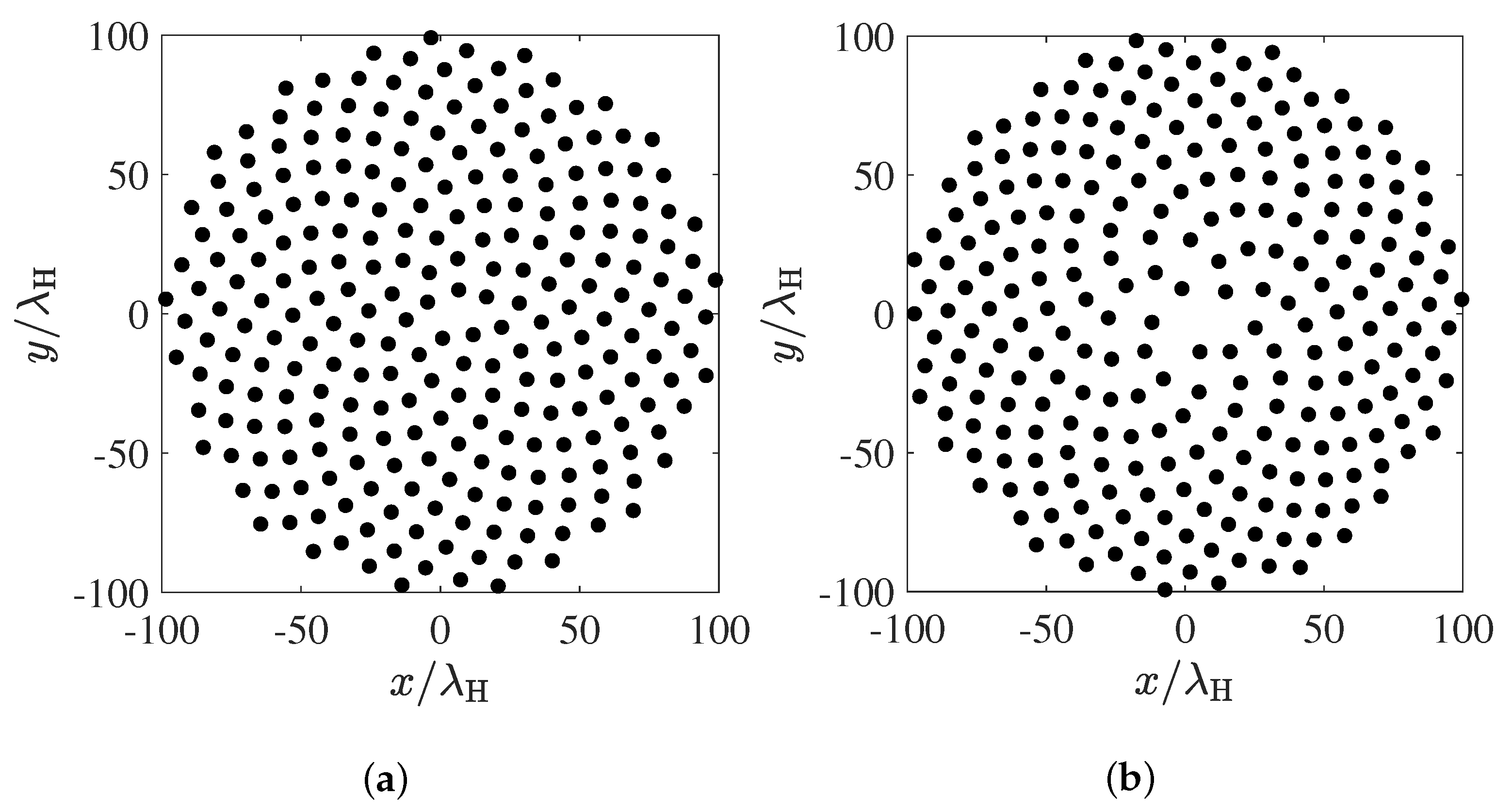
Figure 1. PSLL results of Fermat spiral arrays [15] and parameter–optimized spiral arrays for cases of different numbers of elements. The dotted lines and solid lines represent the results of Fermat spiral arrays and parameter–optimized spiral arrays, respectively.
Electronics 12 01664 g001
Figure 2. (a) Array layout of the 256–element Fermat spiral array [15] and (b) array layout of the 256–element parameter–optimized spiral array.
Electronics 12 01664 g002
Figure 3. Array factor cuts where the peak sidelobes are located. The dashed line indicates the φ = 126 . 5 array factor cut of the Fermat spiral array in Figure 2a, and the solid line indicates the φ = 152 array factor cut of the parameter–optimized spiral array in Figure 2b.
Electronics 12 01664 g003
Figure 4. (a) Array layout of the 551−element perturbed Penrose array [12] and (b) array layout of the 551–element parameter–optimized spiral array.
Electronics 12 01664 g004
Figure 5. Array factor cuts where the peak sidelobes are located. The dashed line indicates the φ = 90 array factor cut of the perturbed Penrose array in Figure 4a, and the solid line indicates the φ = 95 array factor cut of the parameter–optimized spiral array in Figure 4b.
Electronics 12 01664 g005
Figure 6. PSLL results of perturbed Penrose array [12] and parameter–optimized spiral array.
Electronics 12 01664 g006
Table 1. The Geometric Parameters of Fermat Spiral Array and Parameter-Optimized Spiral Array with Different Sizes.
NFermat Spiral ArrayParameter-Opt. Spiral Array
s r Δ ϕ s r Δ ϕ
64 0.093 0.5 137 . 51 0.131 0.419 106 . 55
128 0.093 0.5 137 . 51 0.122 0.448 106 . 39
256 0.093 0.5 137 . 51 0.137 0.432 97 . 15
512 0.093 0.5 137 . 51 0.115 0.466 64 . 08
Disclaimer/Publisher’s Note: The statements, opinions and data contained in all publications are solely those of the individual author(s) and contributor(s) and not of MDPI and/or the editor(s). MDPI and/or the editor(s) disclaim responsibility for any injury to people or property resulting from any ideas, methods, instructions or products referred to in the content.

