Article

Peak Arm Current Minimization of Modular Multilevel Converter Using Multiple Circulating Current Injection

1
Science and Technology Research Institute, China Three Gorges Corporation, Beijing 100000, China
2
School of Electronic Information and Electrical Engineering, Shanghai Jiao Tong University, Shanghai 200240, China
*
Author to whom correspondence should be addressed.
Electronics 2023, 12(7), 1695; https://doi.org/10.3390/electronics12071695
Submission received: 16 March 2023 / Revised: 31 March 2023 / Accepted: 2 April 2023 / Published: 3 April 2023
(This article belongs to the Special Issue Advancement in Power Electronics and Control)

Abstract

:
Conventional circulating current (CC) control schemes of the modular multilevel converters (MMC) typically suppress the CC to zero to reduce the system loss. However, the non-zero CC can also bring additional benefits. In this paper, a peak arm current minimization method of the MMC using multiple circulating current injection control (MCCIC) is studied. Specifically, the second-order CC (SOCC) and the fourth-order CC (FOCC) are used to achieve this purpose. Firstly, the amplitude and phase angle of the SOCC are determined to shape the arm current into a saddle wave. Next, the amplitude and the phase angle of the FOCC are studied to further cut flat the crest of the saddle wave to minimize the peak arm current. The feasibility boundary for the proposed strategy is discussed quantitatively. Moreover, a decoupling circulating current control strategy is developed for precise control of the SOCC and FOCC. In the end, the proposed techniques are verified via both PSCAD/EMTDC simulation and RTLAB&RTU-BOX hardware-in-the-loop experiment. The results show that the peak arm current of the MMC operating with high power factors can be reduced by about 23% and its power handling capacity can be increased by about 30%.

1. Introduction

Nowadays, the modular multilevel converter (MMC) has become one of the most attractive topologies for high-voltage and high-capacity applications [1,2]. The MMC has been widely used in the field of high-voltage DC transmission (HVDC) systems [3] thanks to its modularity, scalability, high efficiency, and low harmonics [4], etc. Under the background of vigorous development of new energy, the development of the MMC-based HVDC system (MMC-HVDC) is flourishing [5,6,7].
The current MMC-HVDC transmission system has reached GW-class capacity [8], whose massive input may trigger problems such as insufficient strength and low inertia of the power system [9]; thus, making short-time frequency stability one of the most pressing security issues in modern power systems [10,11]. Hence, MMC-HVDC systems may be expected to provide ancillary services to the grid where they are located [12,13]. While doing so, the MMC already operating at rated capacity must be capable of moving outside its rated operation range, which means that the MMC has been endowed with overload capability. However, the IGBT modules are sensitive to both overvoltage and overcurrent phenomena, so the operational limits of the IGBT modules in terms of Safe Operating Area (SOA) must be respected [14]. Undoubtedly, this issue can be overcome by using oversized IGBT modules that can reliably switch the increased peak current. However, this approach would significantly increase the investment cost of the system.
Alternatively, the overload capability of the MMC can be achieved simply by proper control techniques, i.e., by reducing the peak current flowing through the MMC, which allows the MMC to deal with more power without increasing the rating of the IGBT modules. The exploration of control schemes for peak current reduction of the MMC needs to be incorporated with its operating characteristics. It is widely known that the currents circulating between the three phases of the MMC, commonly referred to as the circulating current (CC), are intrinsic characteristics of the converter [15,16], where the second-order CC (SOCC) and the fourth-order CC (FOCC) dominate in this three-phase CC [17,18]. Reference [19] claims that the peak arm current of the MMC can be reduced by a reasonable SOCC injection. As a result, the MMC can handle more active power when using the same rating of IGBT modules. However, the specific design method of the SOCC is not presented. Moreover, the scheme does not take the combination of the FOCC into account.
Undoubtedly, the control design of the CC is an essential part of the MMC, which plays a significant role in its operational performance. The existing CC control targets can be summarized as follows.
(1)
CC elimination control (CCEC). The elimination of the CC is a commonly adopted control target, which aims to reduce the power loss of the MMC by reducing the RMS of its arm current [20,21]. However, power loss reduction by this mean is quite insignificant since the CC only increases the RMS of the arm current slightly [22]. In addition, the elimination of the CC will increase the peak arm current of the MMC compared with the scenario where the CC is naturally present [23].
(2)
CC injection control (CCIC). The presence of a moderate CC in the arm current of the MMC is acceptable and it can be utilized as a control freedom to optimize the characteristics of the MMC. Compared with the control target of the CCEC, this group can be uniformly categorized as the CCIC. Following this idea, researchers have conducted in-depth studies on the links between the CCIC technique and the performance improvement of the MMC, such as capacitor voltage ripple suppression [24,25], thermal management optimization [26,27], and operation region extension that has been presented in [19], etc. Compared with the CCEC, the CCIC trades off the conversion efficiency of the system in exchange for the MMC’s performance improvement in a particular area. Therefore, the CCIC is suitable for scenarios where there are special requirements for a particular aspect of the MMC.
The control implementation of the CCEC mainly relies on a synchronously rotating reference frame that utilizes the classical Park transformation for executing control loops in the dq coordinate system [20,28]. Similarly, the CC control in the αβ coordinate system can also be achieved using the classical Clark transformation [29,30]. Some advanced CC control structures, such as the energy-based control structure [31] and the repetitive controller-based control technique [32], have also been developed to achieve better CC control performance. However, the complex multi-objective optimization process and the lack of intuition may limit the application of these methods. In fact, it is possible to achieve unification between the CCEC and the CCIC in terms of control implementation, i.e., the control loops are identical, while their control reference values are different. In general, the reference values of the control loop of the CCEC are set to zero, while those of the CCIC are non-zero quantities designed to improve the performance of the MMC.
In order to extend the P/Q operation range of the MMC set by the peak arm current, multiple circulating current injection control (MCCIC)-based peak arm current minimization technique is proposed in this paper; which, can further reduce the MMC peak current by simultaneously injecting SOCC and FOCC into the arm current in comparison with [19] only injecting SOCC into the arm current. The major contributions of this paper include:
(1)
It reveals the relationship among the SOCC, the FOCC, and the peak arm current of the MMC under various power factors.
(2)
The optimal magnitudes and phase angles of the SOCC and the FOCC allowing for peak arm current minimization of the MMC have been designed in detail under various operating conditions. It can further reduce the peak arm current of the MMC in comparison with the technique proposed in [19], leading to enhanced power handling capacity of the MMC.
(3)
It designs a decoupling control strategy to obtain accurate control of the SOCC and the FOCC.
The following is the organization of this paper. Section 2 shows the structure and operation principle of the MMC and analysis of its peak arm current with the CCEC scheme. Section 3 presents the working principle of the proposed peak arm current minimization control, followed by comprehensive evaluations of the MMC performance in Section 4, including peak arm current reduction, power handling capacity improvement, and system loss increase. Detailed control implementation of the technique and the proposed decoupling circulating current control strategy is explicated in Section 5. The simulation and experiment verification are conducted in Section 6 and Section 7, respectively, to indicate the effectiveness of the method. Finally, Section 8 presents the conclusion.

2. Operation Principle and Peak Arm Current Analysis of the MMC with the CCEC Scheme

2.1. Structure and Operation of the MMC

The circuit configuration of a three-phase MMC is shown in Figure 1a, which is composed of six arms, and each arm consists of N identical submodules (SMs), an arm inductor La, and an equivalent resistance Ra. The upper arm and the lower arm in the same phase form a phase unit. Each SM contains a capacitor and a half-bridge converter that consists of two IGBT modules. The MMC is connected to the point of common coupling (PCC) through a YD-connected transformer.
Figure 1b depicts the equivalent circuit of the MMC based on its Arm Average Model (AAM) [15,31]. The AAM of the MMC comprises many assumptions, such as infinite switching frequency, identical submodule behavior, and linear loss distribution, etc. According to Figure 1b, the upper arm voltage uxp, the lower arm voltage uxn, and the upper arm current ixp, the lower arm current ixn can be described as
{ u x p = U d c 2 e x e c i r x u x n = U d c 2 + e x e c i r x , { i x p = I d c 3 + i c i r x + i x 2 i x n = I d c 3 + i c i r x i x 2
where Udc and Idc present the DC-side voltage and DC-side current, respectively; icirx denotes the CC flowing through phase x; ex is the inner electromotive force (EMF) driving the current ix; ecirx is the EMF driving the current icirx [31]. Please note that the CC in this paper is defined as the difference between the common-mode current of phase x and one-third of the DC-side current that equally flows into each phase.
In Figure 1a, the phase current ix and the phase voltage usx can be generally expressed as
{ u s x = U m cos ( ω t + θ x ) i x = I m cos ( ω t φ + θ x ) , x = a , b , c
where Um and Im represent the magnitudes of usx and ix, respectively; φ is the phase difference between the voltage usx and the current ix; θx represents the phase sequence angle of positive order, and θa, θb and θc equal 0, −2/3π and 2/3π, respectively; ω is the fundamental angular frequency of the AC grid.
Accordingly, the relationship between Im and Idc can be established as follows [15,22]:
I d c = 3 4 m I m cos φ
where m denotes the modulation index of the MMC, and it equals 2Um/Udc. In general, the rated modulation index of the MMC-HVDC system is usually set as 0.85 [8,15,22].

2.2. Analysis of the Peak Arm Current of the MMC with the CCEC Scheme

Here we take only the upper arm of phase a as an example; the other five arms are also available in the same way.
When the CCEC is used, the current flowing through the upper arm of phase a, i.e., iap_E, can be expressed as
i a p _ E = 1 3 i d c + 1 2 i a = 1 2 I m [ 1 2 m cos φ + cos ( ω t φ ) ]
Accordingly, the waveform of iap_E when the MMC operates in the inverter model can be drawn, as shown in Figure 2a. In Figure 2a, icira2 denotes the SOCC flowing through phase a, which has been controlled to zero in this case.
To obtain the instant at which the peak arm current would occur, (4) is differentiated and equated to zero, as in the following equation:
d i a p _ E d ω t = 1 2 I m sin ( ω t φ ) = 0
Solving the above equation yields
{ sin ( ω t φ ) = 0 cos ( ω t φ ) = ± 1
Obviously, the arm current iap_E attains peak when cos(ωt − φ) = 1, i.e., point A in Figure 2a. Then, the value of point A, i.e., iap_E_A, is
i a p _ E _ A = 1 2 I m [ 1 2 m cos φ + 1 ]
The arm current iap_E attains trough when cos(ωt − φ) = −1, i.e., point B in Figure 2a. Then, the value of point B, i.e., iap_E_B, is
i a p _ E _ B = 1 2 I m [ 1 2 m cos φ 1 ]
Comparing (7) and (8), we can obtain
i a p _ E _ A > | i a p _ E _ B |
As a result, iap_E_A represents the maximum value of iap_E when the MMC operates in the inverter model.
Similarly, Figure 2b shows the waveform of iap_E when the MMC operates in the rectifier model. In this case, the absolute value of point A represents the maximum value of the arm current iap_E.
The maximum value of the arm current of the MMC with the CCEC scheme, i.e., (iap_E)max, under various operating conditions, can be summarized as follows.
( i a p _ E ) max = I m ( 1 4 α + 0.5 )
where α = | m cos φ | .

3. Proposed Control Method for Peak Arm Current Minimization

3.1. Analysis of the Peak Current of the MMC Operating in the Inverter Mode

3.1.1. Single Injection of SOCC

Noteworthy, Reference [19] presents only the concept that an appropriate SOCC injection control can reduce the peak arm current of the MMC. However, no detailed amplitude and phase design methods for the SOCC are investigated. Here, we must fill this gap first.
When injecting a SOCC into phase a, the instantaneous expression of the arm current can be expressed in a general way as
i a p _ I 2 = 1 4 m I m cos φ + 1 2 I m cos ( ω t φ ) + k 2 I m cos ( 2 ω t φ 2 ) i c i r a 2
where iap_I2 denotes the arm current of the phase a upper arm of the MMC when injecting a SOCC; icira2 represents the injected SOCC and φ2 and k2 are its phase angle and normalized magnitude, respectively.
As can be seen from (11), the fundamental-frequency component in iap_I2 attains a peak at ωt = φ. Substituting ωt = φ in (11) yields
i a p _ I 2 = 1 4 m I m cos φ + 1 2 I m + k 2 I m cos ( 2 φ φ 2 )
When the MMC is set to operate in the inverter mode, the DC side current is positive, i.e., cosφ > 0, and therefore, the amplitude of the positive arm current needs to be reduced. In the positive half of the arm current, in order to locate the trough of the SOCC and the peak of the fundamental-frequency current of the arm current in one place, it is necessary to satisfy
{ φ 2 = 2 φ k 2 < 0
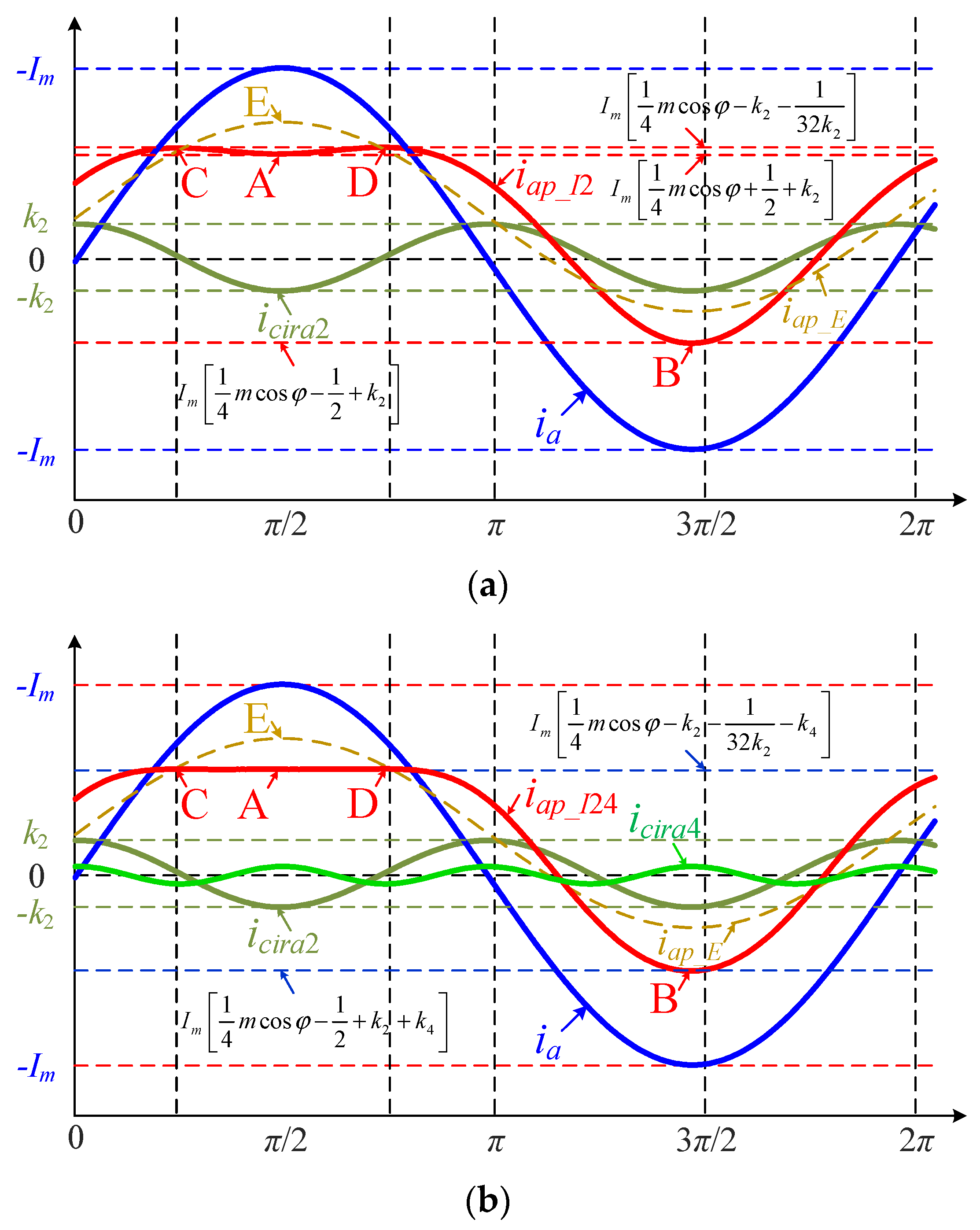
As a consequence, the peak arm current of the MMC will be reduced as long as k2 < 0. Now, the top of the positive part of iap_I2 becomes a saddle wave, as shown in Figure 3a.
Substituting φ2 = 2φ in (11) results in the following:
i a p _ I 2 = 1 4 m I m cos φ + 1 2 I m cos ( ω t φ ) + k 2 I m cos ( 2 ω t 2 φ )
Finding the derivative of (14) with respect to ωt yields
d i a p _ I 2 d ω t = 1 2 I m sin ( ω t φ ) 2 k 2 I m sin ( 2 ω t φ 2 )
Equating (15) to zero, one has
{ sin ( ω t φ ) = 0 cos ( ω t φ ) = 1 8 k 2
It can be seen from (16) that there are four extreme points, which are
{ A : sin ( ω t 1 φ ) = 0 , cos ( ω t 1 φ ) = 1 B : sin ( ω t 2 φ ) = 0 , cos ( ω t 2 φ ) = 1 C : sin ( ω t 3 φ ) = 64 k 2 2 1 8 k 2 , cos ( ω t 3 φ ) = 1 8 k 2 D : sin ( ω t 4 φ ) = 64 k 2 2 1 8 k 2 , cos ( ω t 4 φ ) = 1 8 k 2
The locations of points A, B, C, and D are shown in Figure 3a, respectively. By substituting (17) in (14), the following equations can be obtained.
{ i a p _ I 2 _ A = I m [ 1 4 m cos φ + 1 2 + k 2 ] i a p _ I 2 _ B = I m [ 1 4 m cos φ 1 2 + k 2 ] i a p _ I 2 _ C = I m [ 1 4 m cos φ k 2 1 32 k 2 ] i a p _ I 2 _ D = I m [ 1 4 m cos φ k 2 1 32 k 2 ]
where iap_I2_A, iap_I2_B, iap_I2_C, and iap_I2_D denote the values of the arm current iap_I2 at points A, B, C and D, respectively.
Since k2 < 0, iap_I_B is the smallest of the four extreme points; while, at least one of the other three extreme points is positive. Now, the two cases should be discussed separately.
  • Case I: iap_I2_A = iap_I2_C = iap_I2_D.
In this case, k2 = −1/8 can be obtained. Then, the maximum value of the arm current of the MMC in this case, i.e., (iap_I2)max1, can be deduced as
( i a p _ I 2 ) max 1 = I m [ 1 4 m cos φ + 3 8 ]
  • Case II: iap_I2_A ≠ iap_I2_C = iap_I2_D.
Now, we can easily obtain iap_I2_A < iap_I2_C = iap_I2_D. Then, the maximum value of the arm current of the MMC in this case, i.e., (iap_I2)max_k2, can be deduced as
( i a p _ I 2 ) max _ k 2 = I m [ 1 4 m cos φ k 2 1 32 k 2 ]
As can be observed, the value of (iap_I2)max_k2 is a function of k2. To obtain the instant at which (iap_I2)max_k2 is minimized, (20) is differentiated and equated to zero, as in the following equation:
d ( i a p _ I 2 ) max _ k 2 d k 2 = I m + I m 32 k 2 2 = 0
According to (21), we can obtain
k 2 = 2 8
Then, the maximum value of the arm current of the MMC with a single injection of SOCC, i.e., [(iap_I2)max_k2]max, can be deduced as
[ ( i a p _ I 2 ) max _ k 2 ] min = I m [ 1 4 m cos φ + 2 4 ]
Obviously, [(iap_I2)max_k2]min < (iap_I2)max1 can be obtained.

3.1.2. Joint Injection of SOCC and FOCC

To further reduce the maximum value of the arm current of the MMC, an additional FOCC can be injected to reduce the values of points C and D. When an FOCC is subsequently injected into phase a, the instantaneous expression of the arm current can be expressed in a general way as
i a p _ I 24 = 1 4 m I m cos ( φ + δ ) + 1 2 I m cos ( ω t φ ) 1 4 2 I m cos ( 2 ω t 2 φ ) i c i r a 2 + k 4 I m cos ( 4 ω t φ 4 ) i c i r a 4
where iap_I24 denotes the arm current of phase a upper arm of the MMC when injecting SOCC and FOCC simultaneously; icira4 is the injected FOCC and φ4 and k4 represent its phase angle and normalized magnitude, respectively.
In the positive half of the arm current, in order to locate the trough of the SOCC and the peak of the FOCC in one place, it is necessary to satisfy
{ φ 4 = 4 φ k 4 > 0
Now, recalculating the values of points A and C(D), we can get
{ i a p _ I 24 _ A = I m [ 1 4 m cos φ + 1 2 + k 2 + k 4 ] i a p _ I 24 _ C ( D ) = I m [ 1 4 m cos φ k 2 1 32 k 2 k 4 ]
It can be seen from (26) that the additional injection of the FOCC raises the value of point A while pulling down the values of points C and D.
The maximum value of the MMC arm current with the jointed injection of SOCC and FOCC should be smaller than that when only the SOCC is injected. In other words, the value in (26) should be smaller than that in (23). Consequently, we can obtain
0 < k 4 < 3 2 8 1 2
Moreover, it is known from (26) that the maximum value of the MMC arm current obtains its minimum value when iap_I_A = iap_I_C(D) is satisfied, yielding
k 4 = k 2 1 64 k 2 1 4
Substituting k 2 = 2 / 8 into (28) shows that the value of k4 satisfies the limitation set in (27).
Combining (26) and (28), the maximum value of the MMC arm current with the joint injection of SOCC and FOCC can be expressed as
( i a p _ I 24 ) max = I m [ 1 4 m cos φ + 1 4 + 2 16 ]
Comparing (23) and (29), we can obtain (iap_I24)max < [(iap_I2)max_k2]min.
Now, the value of point B becomes
i a p _ I 24 _ B = I m [ 1 4 m cos φ 1 2 + k 2 + k 4 ]
A schematic diagram of the arm current of the MMC operating in the inverter mode with the jointed injection of the SOCC and the FOCC can be obtained, as shown in Figure 3b. In this figure, icira2 and icira4 indicate the injected SOCC and FOCC, respectively. It can be seen that the top of the positive part of iap_I24 has been cut flat, meaning that the peak arm current has been minimized.

3.1.3. Determination of Feasibility Boundary

It is worth noting that in order to ensure the normal operation of the MMC, the following limitation needs to be met.
{ 1 4 m cos φ + 1 2 + k 2 + k 4 > 0 1 4 m cos φ 1 2 + k 2 + k 4 < 0 | 1 4 m cos φ 1 2 + k 2 + k 4 | 1 4 m cos φ + 1 2
The first two inequalities of (31) are essential for the proper operation of the MMC, i.e., in order to ensure the balance of the submodule capacitor voltages, the arm current of the MMC must have a fraction less than zero and must have a fraction greater than zero. Substituting (22) and (28) into the first two inequalities of (31), one has
{ 1 4 m cos φ + 1 2 + k 2 + k 4 = 1 4 m cos φ + 1 4 + 2 16 > 0 1 4 m cos φ 1 2 + k 2 + k 4 = 1 4 m cos φ 3 4 + 2 16 1 4 3 4 + 2 16 < 0
That is to say, in the case of m > 0 and cosφ > 0, the first two inequalities are definitely satisfied.
The third inequality of (31) indicates the purpose of the proposed strategy. As seen in Figure 3b, although the proposed MCCIC strategy can reduce the peak of the positive half of the arm current, it also pulls down its negative amplitude (point B). Therefore, if the third inequality is not satisfied, it will instead increase the overall peak arm current.
Solving the third inequality of (31) yields
m cos φ > 0.32
In fact, (33) specifies the feasibility boundary of the proposed multiple CC injection technique. When the MMC-HVDC system is expected to provide short-term frequency-supporting service by transferring more active power, the system will be set to operate with a unity power factor, i.e., cosφ = 1. Hence, under the envisaged operation condition, mcosφ > 0.85 can be achieved, which means the limitation set in (33) can be satisfied.

3.2. Analysis of the Peak Current of the MMC in the Rectifier Mode

When the MMC is set to operate in the rectifier mode, the DC side current Idc is negative, i.e., cosφ < 0, and therefore, the amplitude of the negative arm current needs to be suppressed. In the negative half of the arm current, the peak of the SOCC should be aligned with the trough of the fundamental-frequency component of the arm current; while, the trough of the FOCC should be aligned with the peak of the SOCC. Consequently, we can obtain
{ k 2 = 1 4 2 k 4 = k 2 1 64 k 2 + 1 4
Similarly, it is known that the feasibility boundary of the MMC operates in the rectifier mode is
m cos φ > 0.32
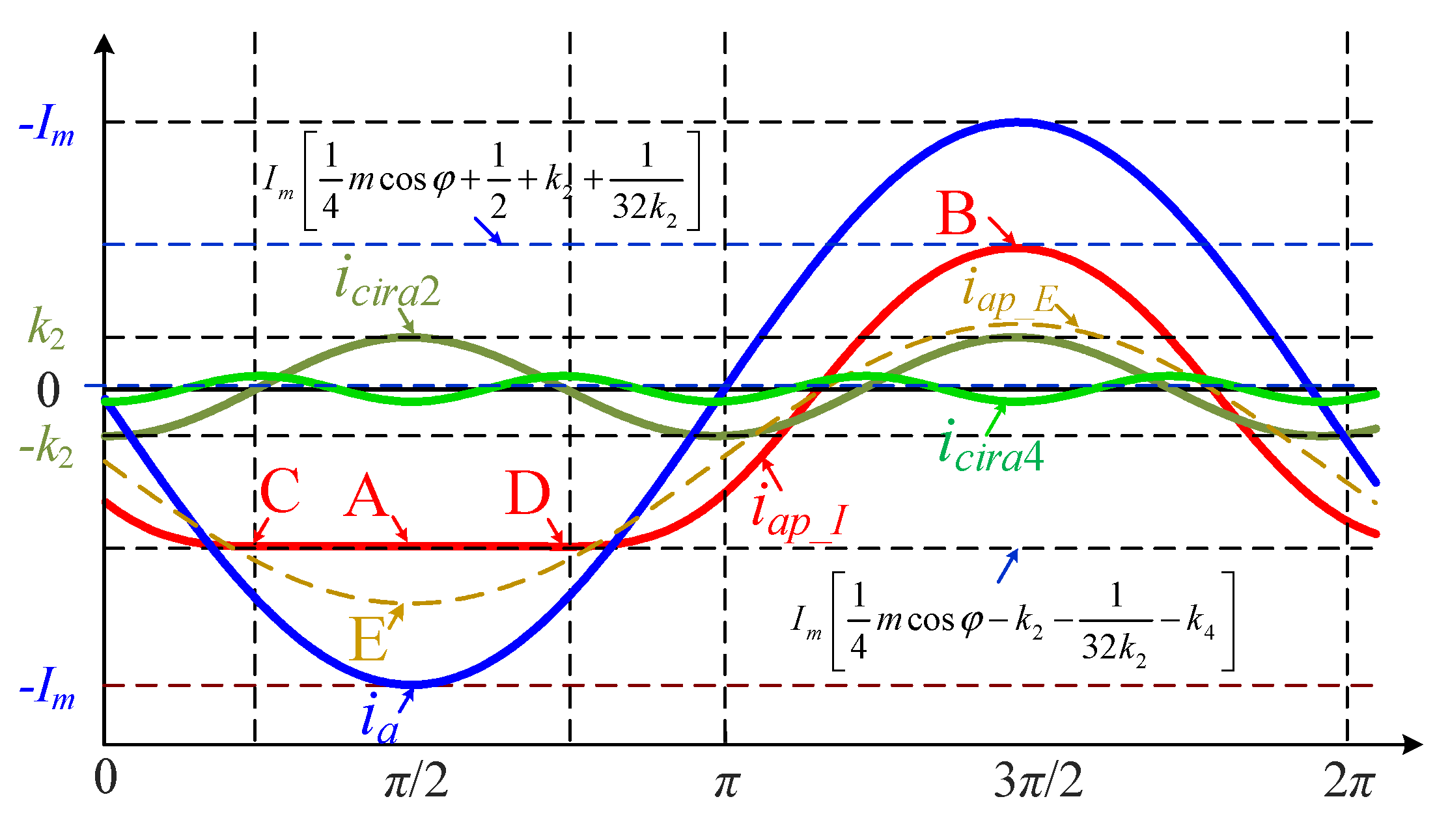
The schematic diagram of the arm current in the rectifier mode is shown in Figure 4. The derivation process is similar to that in Section 3.1 and will not be repeated.
To sum up, the values of k2 and k4 under various operating conditions can be gathered as
Inverter   mode : k 2 = { 2 8 0.32 < α 1 0 0 α 0.32 k 4 = { 3 2 16 1 4 0.32 < α 1 0 0 α 0.32 Rectifier   mode : k 2 = { 2 8 0.32 < α 1 0 0 α 0.32 k 4 = { 3 2 16 + 1 4 0.32 < α 1 0 0 α 0.32
Then, the maximum value of the arm current with the proposed MCCIC scheme under various operating conditions can be summarized as follows.
( i a p _ I 24 ) max = { I m ( 1 4 α + 0.34 ) 0.32 < α 1 I m ( 1 4 α + 0.5 ) 0 α 0.32

4. Evaluation of the Performance of the MMC with the MCCIC Scheme

4.1. Evaluation of the Arm Current Reduction

Define ηI as
η I = ( i a p _ E ) max ( i a p _ I 24 ) max ( i a p _ E ) max × 100 %
In fact, ηI measures the percentage reduction of the maximum value of the arm current when using the proposed MCCIC technique. It is worth noting that ηI is a definition specific to this paper and does not have a broad meaning.
Substituting (10) and (37) into (38), we can obtain
η I = { 65 α + 2 0.32 < α 1 0 0 α 0.32
The numerical method allows drawing the values of ηI with the variation of α in the interval scale α∈[0, 1]. The result is depicted in Figure 5a. It can be seen that ηI is inversely proportional to α when α∈[0.32, 1]. Therefore, ηI achieves its maximum value when α = 0.32, which is 28.1%; and ηI achieves its minimum value when α = 1, which is 21.7%. When α∈[0, 0.32], ηI = 0 can be got due to no CCs will be injected. In other words, the proposed method allows the MMC operating at high power factors to utilize IGBT modules of 21.7% lower current rating with the same power levels.

4.2. Evaluation of the Power Handling Capacity Improvement

When the peak arm current of the MMC is reduced, its power handling capacity will be enhanced for the same rating of IGBT modules. This is beneficial to move the MMC into the overloaded operation region.
Define ηP as
η P = η I 100 η I × 100 % = ( i a p _ E ) max ( i a p _ I 24 ) max ( i a p _ I 24 ) max × 100 %
It is clear that ηP measures the percentage increase of the power handling capacity when using the proposed MCCIC technique.
Substituting (10) and (37) into (40), we can obtain
η I = { 65 100 α + 135 0.32 < α 1 0 0 α 0.32
The values of ηP with the variation of α in the interval scale α ∈ [0, 1] are shown in Figure 5b. As can be observed, ηP is inversely proportional to α when α ∈ [0.32, 1]. Therefore, ηP achieves its maximum value when α = 0.32, which is 38.9%; and ηP achieves its minimum value when α = 1, which is 27.7%. when α∈[0, 0.32], we have ηI = 0. As a result, with the same rating of IGBT modules, the MMC can output more than 27.7% of the rated active power that is set by the peak arm current, which facilitates bringing the MMC into the overload operation region.

4.3. Evaluation of the System Loss Increase

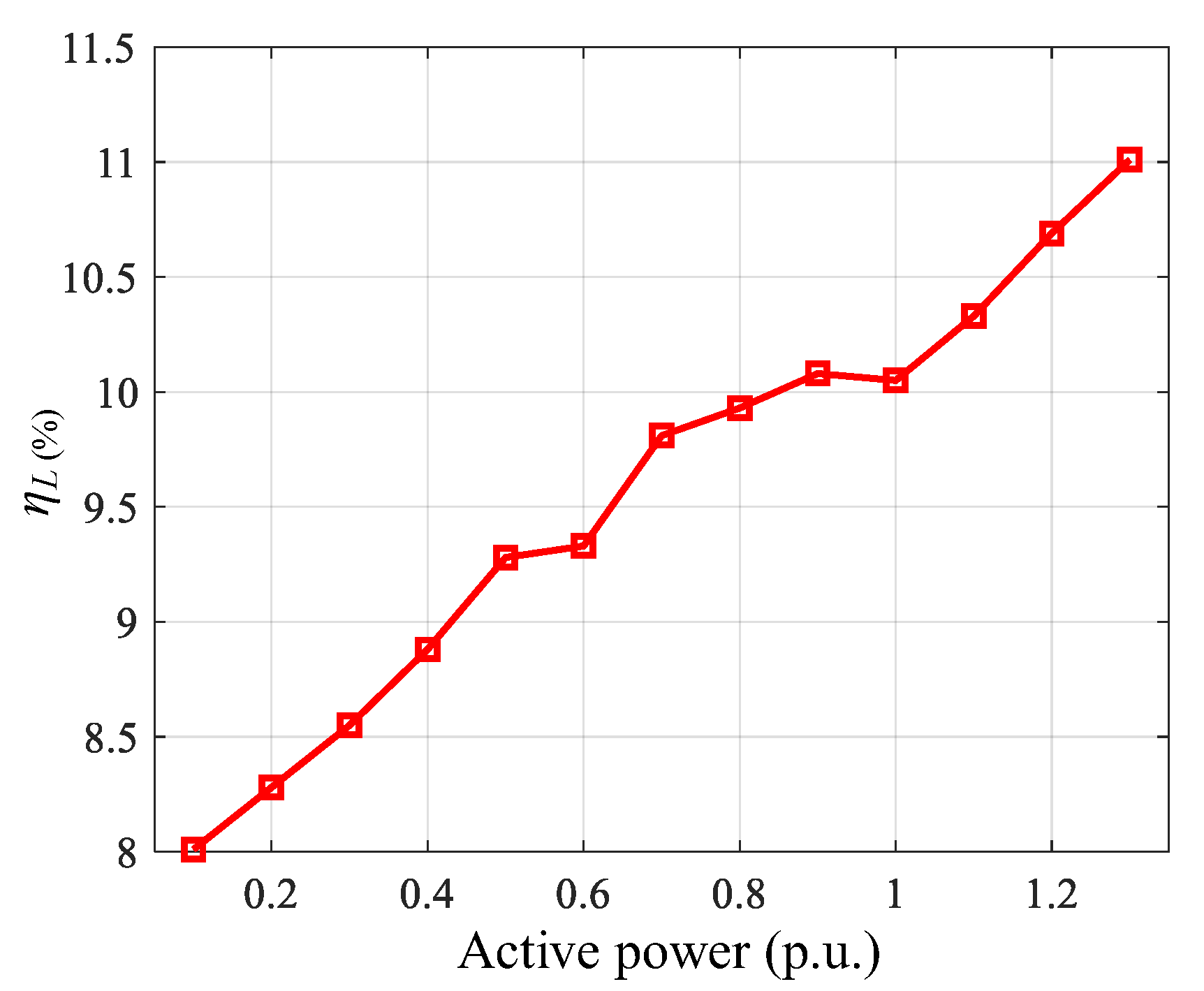
Compared with the CCEC scheme, the losses of the MMC system will be increased inevitably as the proposed strategy injects the SOCC and the FOCC into the arm currents. The total losses of the MMC system can be computed analytically using the method proposed in [33]. In this paper, the total system loss is calculated for the two different schemes (the CCEC scheme and the MCCIC scheme) by using the parameters of the ABB IGBT module of rating 3000 A, 4500 V (5SNA 3000K452300) [34]. Figure 6 depicts the percentage increase in system losses, i.e., ηL, which is defined as
η L = P I P E P E × 100 %
where PI and PE denote the losses of the MMC system using the MCCIC scheme and CCEC scheme, respectively.
As can be seen, the MMC losses with the MCCIC scheme are about 11% higher than those with the CCEC scheme at high active power levels. However, the active power handling capacity of the MMC can be improved by more than 27.7% under these operating conditions. Besides, the duration of the short-term frequency support service is usually around a few seconds; which, means that the economic losses due to the increased losses can be negligible.

5. Controller Implementation and Decoupling Control of SOCC and FOCC

5.1. Controller Implementation

In this paper, the PCC is set at the grid side of the transformer. According to the commonly used vector-based control structures [31], the current amplitude Ism and the power factor angle φs of the PCC can be expressed as
{ I s m = i s d 2 + i s q 2 φ s = arctan ( i s q i s d )
where isd and isq denote the direct-axis component and quadrature-axis component of the three-phase grid currents.
For a transformer with YD11 connection, the converter-side currents lead the gird-side current by π/6; therefore, the converter-side current ix can be written as
i x = I s m k T cos [ θ p φ s + π 6 + θ x p ]
where θp is the output of the Phase-Locked Loop (PLL); kT is the ratio of the transformer; θxp represents the phase sequence angle of positive order, and θap, θbp and θcp equal 0, −2/3π and 2/3π, respectively.
Combining (11), (13) and (44), the reference value of the injected SOCC of phase x is given by
i c i r x r e f 2 = k 2 I s m k T cos [ 2 θ p 2 φ s + π 3 + θ x n ]
where θxn represents the phase sequence angle of negative order, and θan, θbn, and θcn equal 0, 2/3π and −2/3π, respectively.
Similarly, combining (24), (25) and (44), the reference value of the injected FOCC of phase x can be deduced as
i c i r x r e f 4 = k 4 I s m k T cos [ 4 θ p 4 φ s + 2 π 3 + θ x p ]
Reference [20] proposed a CC control architecture that decomposes the three-phase CCs into two DC components based on the double line-frequency negative-sequence rotational frame, and the two DC components are vanished by a pair of proportional–integral (PI) controllers. The control’s simple structure and ease of implementation make it one of the most commonly used CC control frameworks. When the reference values of the two DC components are both set to zero, CCEC can be achieved. Similarly, when the reference values of the two DC components are set to the values calculated in this paper, MCCIC-based peak arm current minimization control can be achieved. Hence, only the reference values of the CC control proposed in [20] change, while, the control architecture and control parameters are identical; thus, making the proposed strategy easy to implement in the industry.
The reference values of the injected SOCC and the FOCC in the dq coordinate system can be gathered as
{ [ i c i r d r e f 2 , i c i r q r e f 2 ] T = T 3 s / d q ( 2 θ p ) [ i c i r a r e f 2 , i c i r b r e f 2 , i c i r c r e f 2 ] T [ i c i r d r e f 4 , i c i r q r e f 4 ] T = T 3 s / d q ( 4 θ p ) [ i c i r a r e f 4 , i c i r b r e f 4 , i c i r c r e f 4 ] T
where T3s/dq(•) is the transformation matrix of the abc stationary coordinate system to the dq rotating coordinate system. The expression of T3s/dq(•) is given as follows:
T 3 s / d q ( θ p ) = 2 3 [ cos ( θ p ) cos ( θ p 2 3 π ) cos ( θ p + 2 3 π ) sin ( θ p ) sin ( θ p 2 3 π ) sin ( θ p + 2 3 π ) ]
Figure 7a illustrates the overall control structure of the proposed peak arm current minimization control. The control structure comprises the following loops.
(1)
The PLL-based dual closed-loop control loops for active power or DC-side voltage, reactive power and the three-phase grid currents;
(2)
The SOCC control links and the FOCC control links;
(3)
The modulation synthesis link and the modulation link;
(4)
A series of coordinate transformation links.
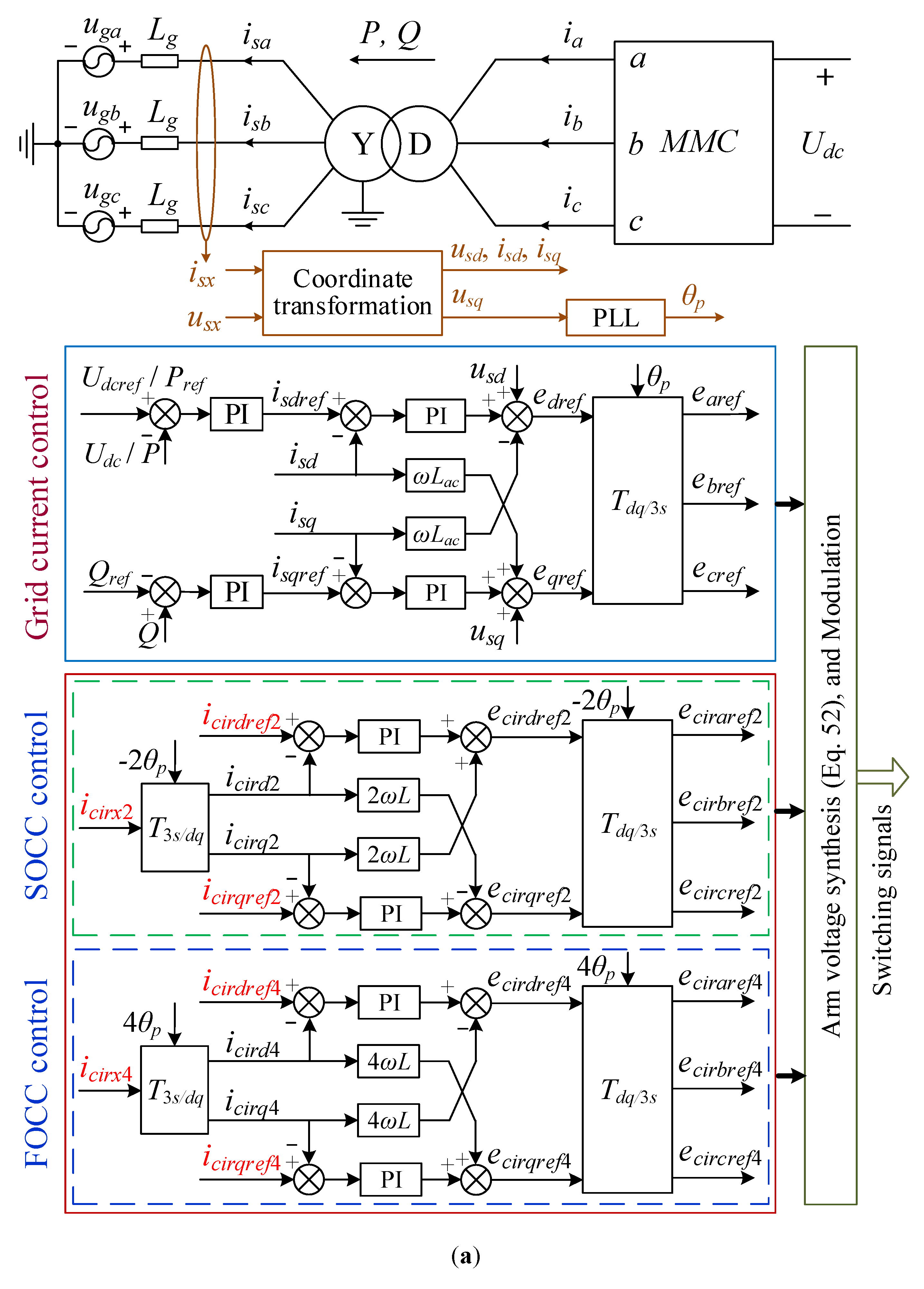
Figure 7. Block diagram of the proposed MCCIC-based peak arm current minimization technique of the MMC: (a) overall control block diagram; (b) block diagram for calculating decoupling actual values of the SOCC and the FOCC.
Electronics 12 01695 g007aElectronics 12 01695 g007b
In Figure 7a, earef, ebref, and ecref denote the fundamental-frequency EMFs driving the grid currents ia, ib, and ic, respectively; eciraref2, ecirbref2, and ecircref2 denote the second-order EMFs driving the SOCCs icira2, icirb2, and icirc2, respectively; eciraref4, ecirbref4, and ecircref4 denote the fourth-order EMFs driving the FOCCs icira4, icirb4, and icirc4, respectively. According to (1), the ultimate modulation voltages of the six arms of the MMC are given as follows:
phase A { u a p r e f = 1 2 U d c e a r e f e c i r a r e f 2 e c i r a r e f 4 u a n r e f = 1 2 U d c + e a r e f e c i r a r e f 2 e c i r a r e f 4 phase B { u b p r e f = 1 2 U d c e b r e f e c i r b r e f 2 e c i r b r e f 4 u b n r e f = 1 2 U d c + e b r e f e c i r b r e f 2 e c i r b r e f 4 phase C { u c p r e f = 1 2 U d c e c r e f e c i r c r e f 2 e c i r c r e f 4 u c n r e f = 1 2 U d c + e c r e f e c i r c r e f 2 e c i r c r e f 4

5.2. Decoupling Control of SOCC and FOCC

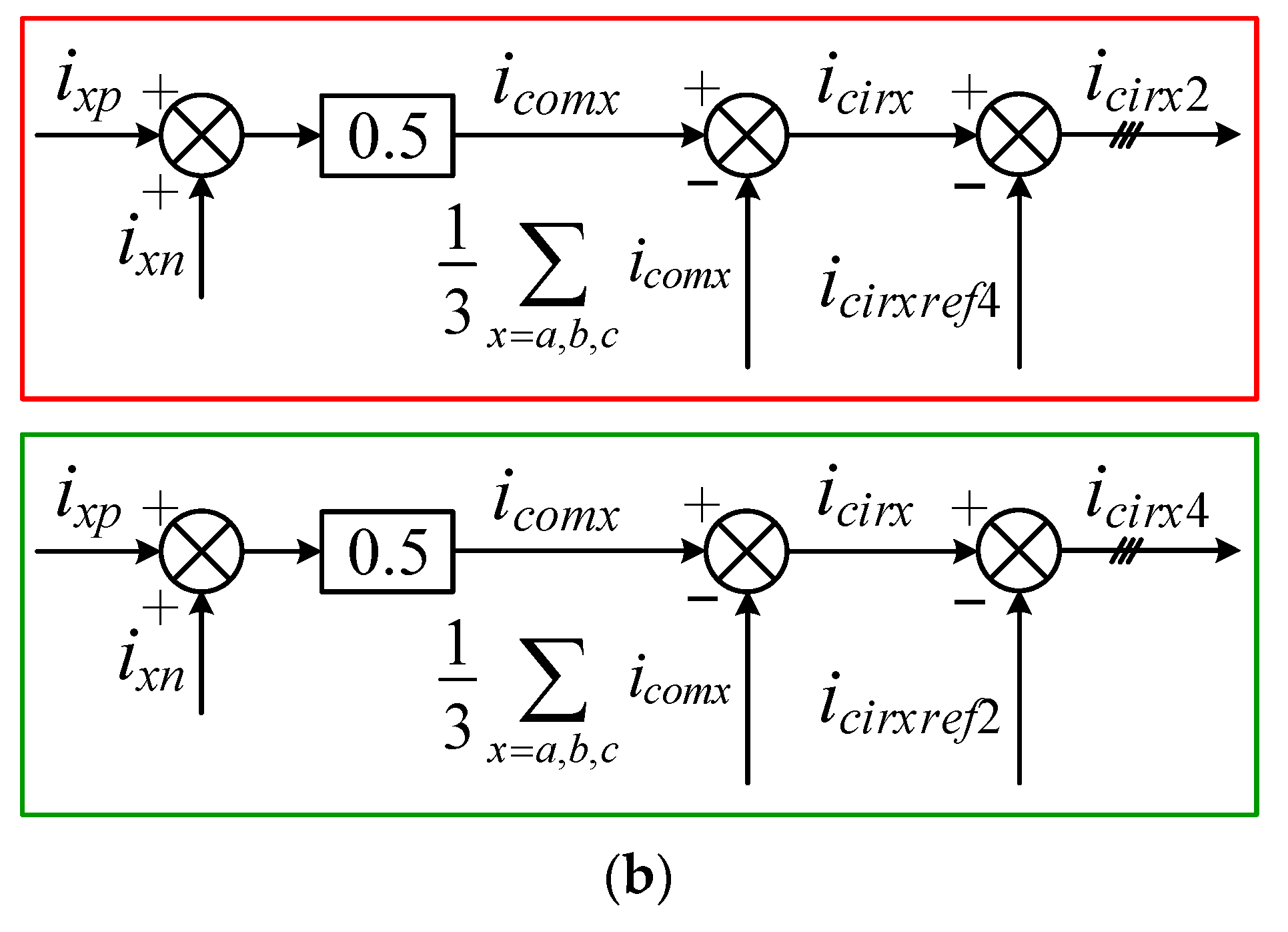
As shown in Figure 7a, the SOCC and the FOCC are controlled by sending the differences between their reference values and the actual values in the dq coordinate system to the PI controllers, respectively. Now, another key issue that should be addressed is that [12] only regulates the SOCC, while the FOCC is left uncontrolled. However, in this paper, the SOCC and the FOCC are injected simultaneously. The reference values of the two CCs are non-zero and different from each other. Thereby, the coupling will occur if the actual values of the total CC are used directly to obtain the actual values of the SOCC and the FOCC in the dq coordinate system. To deal with this problem, a decoupling control strategy, which is shown in Figure 7b, is proposed for the case where multiple CCs need to be controlled simultaneously.
The working principle of the proposed decoupling control strategy lies in the fact that the bandwidth of the CC control is usually designed to be relatively high [29,30,31]. Hence, it can be assumed that the actual value of the CC is exactly equal to its reference value. Then, the actual value of the SOCC can be obtained by subtracting the reference value of the FOCC from the actual value of the total CC. Similarly, subtracting the reference value of the SOCC from the actual value of the total CC will yield the actual value of the FOCC. The procedures to calculate decoupling actual values of the SOCC and the FOCC are depicted as follows.
The common-mode current icomx should be obtained first, which contains both the DC component and the CC components. That is
i c o m x = 1 2 ( i x p + i x n ) = 1 3 x = a , b , c i c o m x + i c i r x
Then, the CC of phase x can be extracted as
i c i r x = i c o m x 1 3 x = a , b , c i c o m x
Accordingly, the expressions for the actual value of the SOCC of phase x, i.e., icirx2, and the actual value of the FOCC of phase x, i.e., icirx4, can be deduced as
{ i c i r x 2 = i c i r x i c i r x r e f 4 i c i r x 4 = i c i r x i c i r x r e f 2 , x = a , b , c
Finally, the actual values of the injected SOCC and the FOCC in the dq coordinate system can be given as follows:
{ [ i c i r d 2 , i c i r q 2 ] T = T 3 s / d q ( 2 θ p ) [ i c i r a 2 , i c i r b 2 , i c i r c 2 ] T [ i c i r d 4 , i c i r q 4 ] T = T 3 s / d q ( 4 θ p ) [ i c i r a 4 , i c i r b 4 , i c i r c 4 ] T
Now, all the control variables required for the MCCIC-based peak arm current minimization technique have been obtained. Obviously, the proposed technique simply makes use of the variables already present in the main control system; which, implies that it avoids the utilization of additional hardware circuits and the subsequent increase of the system complexity and costs. Moreover, it requires only some basic mathematical operations, so the control burden will be not unduly increased.

6. Simulation Verification

To verify the proposed method, a three-phase MMC, extracted from China’s Zhangbei multiterminal DC system [13,31], is built in the PSCAD/EMTDC platform. The simulation parameters of the MMC are given in Table 1.
In each of the following simulations, the three subgraphs from top to bottom are:
(1)
Active power P and reactive power Q;
(2)
Grid current ia, SOCC icira2 and FOCC icira4 of phase a;
(3)
Upper arm current iap and lower arm current ian of phase a.

6.1. Performance of the MMC in the Inverter Mode

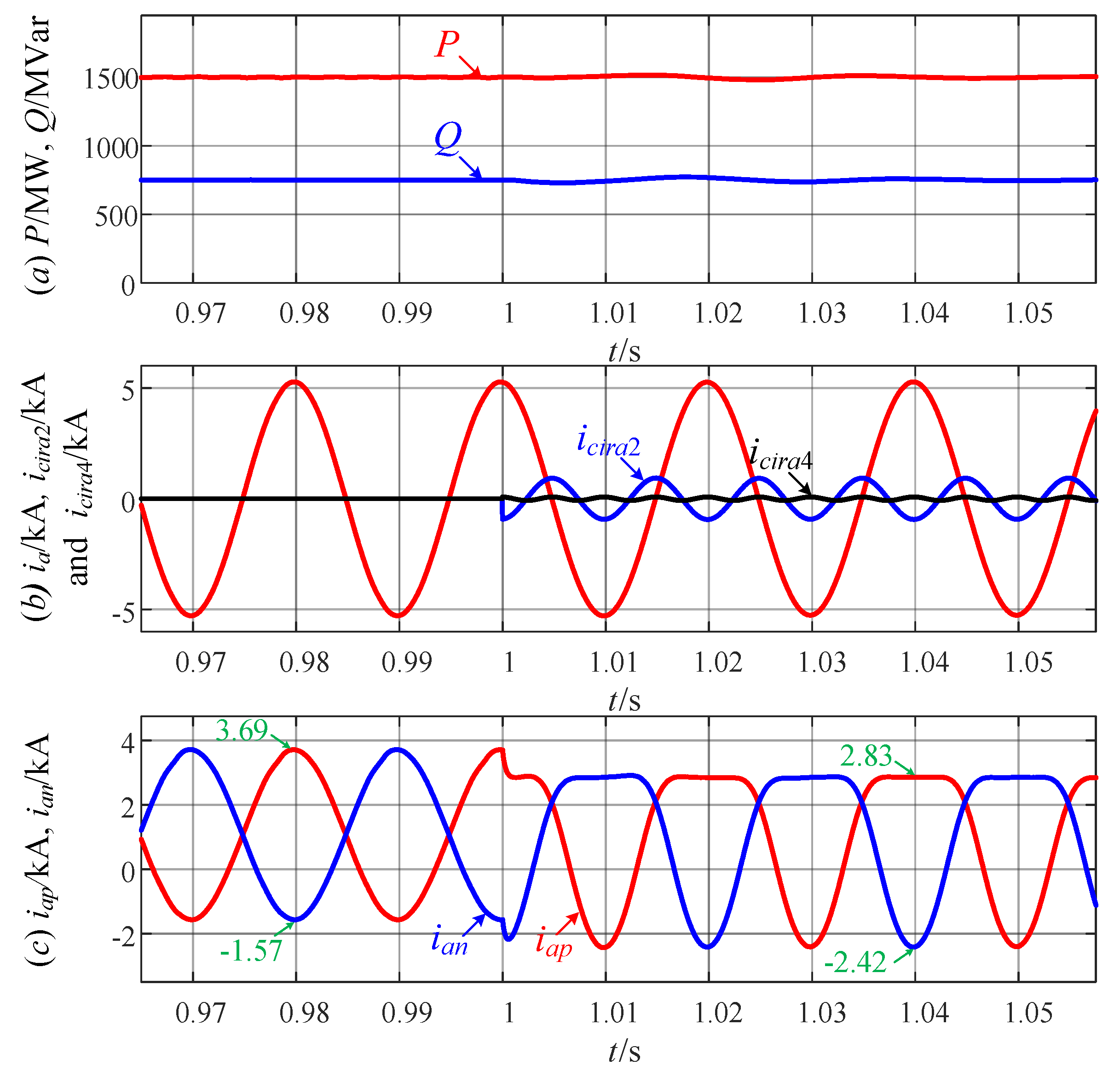
The performance of the MMC operating in the inverter mode before and after using the proposed MCCIC technique is verified first. The active and reactive power reference values are initialized to 1500 MW and 750 MVar, respectively. The MMC is set to operate in the CCEC strategy before t = 1 s; when t = 1 s, it is switched to the proposed MCCIC strategy. The simulation results are shown in Figure 8.
As can be seen from Figure 8, in the positive half of the arm current, the trough of the SOCC is aligned with the peak of the fundamental-frequency component of the arm current, and the peak of the FOCC is aligned with the trough of the SOCC, which states that the precise control of the SOCC and the FOCC has been achieved.
The comparison of the calculated and simulated results for each point of the arm currents in Figure 3b for this operating condition is shown in Table 2, where the first row of each item indicates the theoretical value and the second row indicates the actual value read from the simulation waveforms. It can be seen that the calculated results match with the simulation results, verifying the correctness of the theoretical analysis. According to Figure 2a and Figure 3b, we know that IE and IC(D) denote the maximum values of the arm currents with the CCEC scheme and the MCCIC scheme, respectively. The peak arm current is reduced by 23.3%, which matches with the calculated result of (39) of 23.6%.

6.2. Performance of the MMC in the Rectifier Mode

The performance of the MMC operating in the rectifier mode before and after using the proposed MCCIC strategy is shown in Figure 9. The active and reactive power references are initialized to −1500 MW and 0, respectively. Set the MMC operating in the CCEC strategy before t = 1 s, and then switch the MMC to the proposed strategy when t = 1 s.
It can be observed from Figure 9, in the negative half of the arm current, the peak of the SOCC is aligned with the trough of the fundamental-frequency current of the arm current, and the trough of the FOCC is aligned with the peak of the SOCC. Therefore, accurate control of the SOCC and the FOCC can be obtained by the designed CC decoupling control technique.
The comparison of the calculated and simulated results for each point of the arm currents in Figure 4 for this operating condition is also shown in Table 2. As can be seen, the calculated results are consistent with the simulation results, verifying the correctness of the theoretical analysis. According to Figure 2b and Figure 4, one knows that IE and IC(D) denote the maximum values of the arm currents with the CCEC scheme and the MCCIC scheme, respectively. Obviously, the arm current of the MMC is reduced by 23.0%, which matches with the calculated result of (39) of 23.2%.

6.3. Dynamic Performance of the MMC Considering Switching Processing

Next, the dynamic performance of the MMC considering switching processing when using the proposed MCCIC method is verified because k2 and k4 must be switched under different operating conditions. The smoothness of this switch processing will be examined here. The simulation result of this case is shown in Figure 10, where the green dashed line indicates the current waveform of the phase a upper arm when using the CCEC strategy for the same operating conditions. The working conditions of this simulation are set as follows.
(1)
Stage 1 [t < 1 s]: the MMC is set to operate in (P = 1500 MW, Q = 750 MVar) condition. In this stage, the maximum value of the arm current is reduced by 23.0%.
(2)
Stage 2 [1 s < t < 1.06 s]: the MMC is set to operate in (P = 0, Q = 750 MVar) condition. In this stage, k2 = k4 = 0 can be obtained since α is less than 0.32. Hence, the arm current waveform of the MCCIC strategy is the same as that of the CCEC strategy.
(3)
Stage 3 [t > 1.06 s]: the MMC is set to operate in (P = −1500 MW, Q = 750 MVar) condition. In this stage, the maximum value of the arm current is reduced by 23.2%.
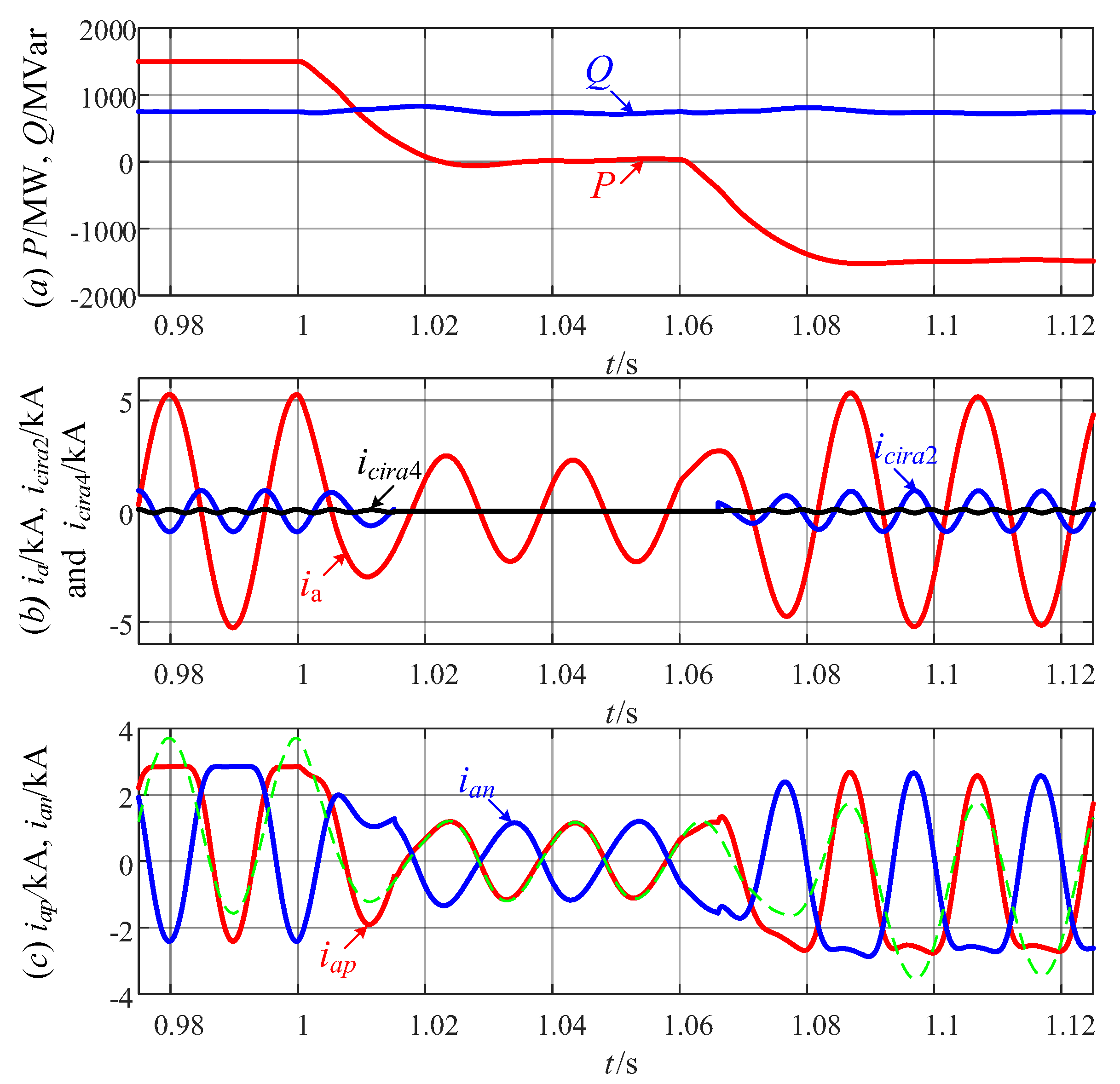
Figure 10. Simulation waveforms of the MMC considering switching processing.
Electronics 12 01695 g010
Additionally, the transfer process of each operating condition is smooth without overshoot and oscillation, verifying the effectiveness of the proposed MCCIC strategy.
According to Figure 8, Figure 9 and Figure 10, it can be concluded that the proposed method leads to a significant reduction in the current rating requirements of the IGBT modules of the MMC operating at high power factors compared to the existing CC control schemes.

6.4. Overload Performance of the MMC

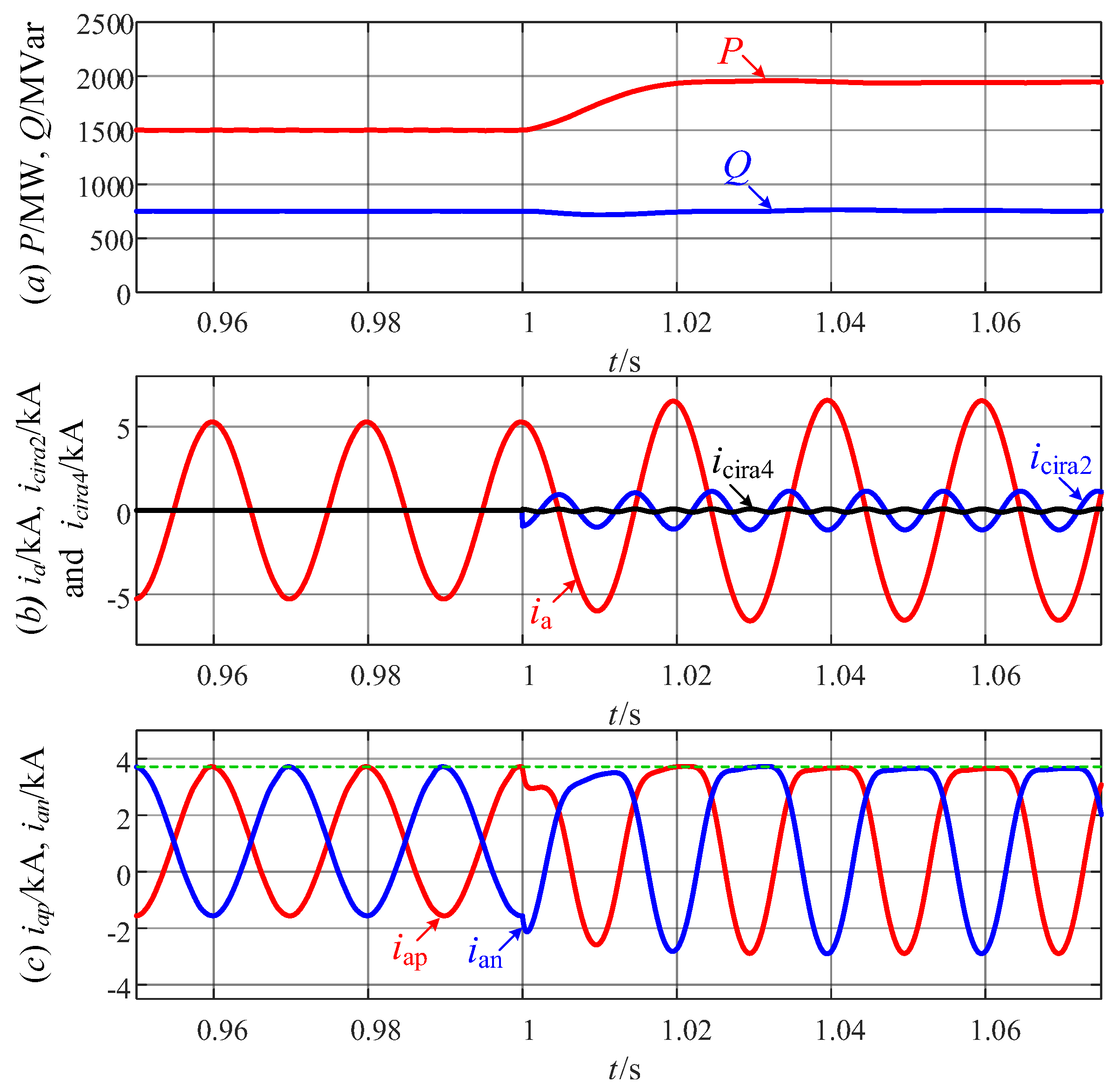
To verify that the MCCIC strategy can improve the power transfer capability of the MMC, it is set to operate at (P = 1500 MW, Q = 750 MVar) condition with the CCEC strategy before t = 1 s; when t > 1 s, the MMC is shifted to (P = 1950 MW, Q = 750 MVar) condition with the proposed MCCIC strategy. The simulation results are shown in Figure 11. It can be seen that after the active power command is increased to 1.3 pu, the maximum value of the arm current is equal to that when the active power is 1 pu under the CCEC strategy. Therefore, we can conclude that the proposed method can extend the operating range of the MMC by minimizing its peak arm current, which facilitates the MMC to provide auxiliary services, such as short-term frequency response during emergency conditions.

7. Experimental Verification

The proposed method is also verified in RT-LAB & RTU-BOX hardware-in-the-loop (HIL) experimental platform. The system setup and configuration used for verification are shown in Figure 12. The switching circuit of the MMC is built in RT-LAB, and the controller shown in Figure 7 is implemented in RTU-BOX with a core of TMS320C28346 DSP. The data between the RT-LAB and the RTU-BOX are exchanged via multiple DB37 cables. The execution cycle of the RT-LAB is 100 μs and the control cycle of the RTU-BOX is 10 μs. The RT-LAB and the RTU-BOX are controlled by two computers. The data delay between the RT-LAB and the RTU-BOX is about 150 μs. The RT-LAB and the RTU-BOX are controlled by two computers.
Due to the performance limitations of the RTLAB, the number of SMs per arm in the HIL experiments is set to 25, which is equal to one-tenth of the simulations. To ensure that the equivalent capacitance C/N remains unchanged, the capacitance C per SM is also reduced by 10 times. Other parameters are the same as simulations.
Figure 13 shows the HIL experimental results of the MMC before and after using the proposed method. The four subgraphs from top to bottom are:
(1)
Active power P and reactive power Q;
(2)
Three-phase AC grid currents isa, isb and isc;
(3)
Three-phase CCs icira, icirb, and icirc (including aggregated SOCC and FOCC);
(4)
Currents flowing through the upper arm and lower arm of phase a, i.e., iap and ian, and the current flowing through the upper arm of phase B, i.e., ibp.
Figure 13. Experimental waveforms of the MMC before and after using the proposed strategy.
Electronics 12 01695 g013
The operating conditions are set as follows.
(1)
Stage 1 [t < 0.04 s]: the CCEC strategy is used and the MMC is set to operate in (P = 1500 MW, Q = 0) condition. In this stage, the maximum value of the arm current is 3.40 kA.
(2)
Stage 2 [0.04 s < t < 0.14 s]: the MCCIC strategy is enabled and the MMC keeps operating in (P = 1500 MW, Q = 0) condition. In this stage, the maximum value of the arm current is 3.62 kA, achieving a reduction of 22.7%.
(3)
Stage 3 [t > 0.14 s]: the MCCIC strategy keeps enabled and the MMC is set to operate in (P = 1500 MW, Q = 750 MVar) condition. In this stage, the maximum value of the arm current is 2.81 kA. Obviously, the arm current waveform of the MMC has been sliced off.
Similar to the simulation results is that the transfer process of each operating condition is smooth without overshoot and oscillation.
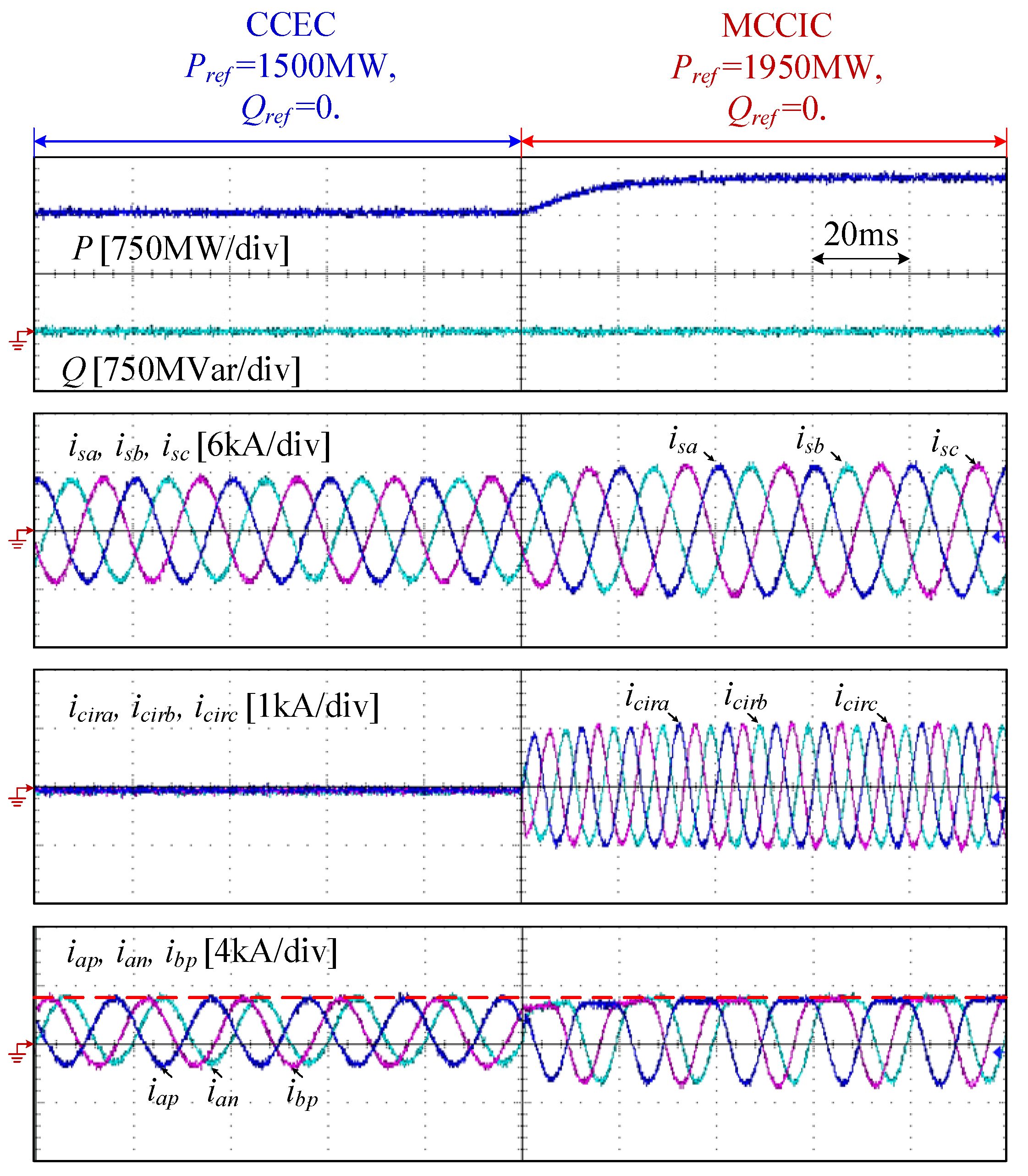
The overload performance of the MMC has also been experimentally validated, which can be seen in Figure 14. The MMC is set to operate in (P = 1500 MW, Q = 0) condition with the CCEC strategy before t = 0.1 s, and then switches to the (P = 1950 MW, Q = 0) condition with the MCCIC strategy.
As can be observed, when the active power is increased to 1.3 pu, the maximum value of the arm current is equal to that when the active power is 1 pu with the CCEC strategy. In other words, the power transfer capacity of the MMC has been enhanced by 30%.

8. Conclusions

In this paper, a peak arm current minimization control strategy of the MMC based on the jointed injection of the SOCC and FOCC is proposed. The following conclusions are obtained.
(1)
By injecting both the appropriate SOCC and FOCC, the maximum value of the arm current can be reduced by about 23%, which allows up to a 30% overload ability of the MMC operating with high power factors beyond its active power limit set by the peak arm current.
(2)
The CC decoupling control technology developed to take advantage of the high bandwidth of the current loop allows precise control of the SOCC and the FOCC to be achieved.
(3)
Compared to the CCEC scheme, the losses of the MMC operating with high active power levels are increased by about 11% when using the proposed scheme. However, this increased loss can be neglected due to the short-term overload operation setting.
The developed peak arm current minimization algorithm is relatively simple because it just uses variables already available from the main control system and only demands some basic mathematical operations. Hence, it can be easily embedded into the main control system without great effort. These advantages are promising for the MMC with critical demand on short-term overload requirements.
It is worth noting that this paper focuses only on specific design approaches for the amplitude and phase of the above two CCs in order to minimize the peak arm current of the MMC, which indicates the most important obstacle to improving its active power transfer capability. However, the obtained overload capability through the MCCIC scheme will be also subject to the thermal constraints of the IGBT modules. Another critical issue to be dealt with is how to obtain the optimal overload capacity of the MMC depending on the maximum allowable junction temperature of the IGBT modules, which will be our future research direction.

Author Contributions

Conceptualization, X.S. and Y.W.; methodology, X.S., Y.W. and X.C.; investigation, J.L. and X.S.; software, X.S. and Y.W.; validation, X.S. and Y.W.; supervision, M.C., J.L., Z.Z. and X.C.; writing—original draft, Y.W.; review and editing, Y.W., X.S., X.L. and Z.Z. All authors have read and agreed to the published version of the manuscript.

Funding

This research was funded by the Scientific Research Project of the China Three Gorges Corporation under Grant 202103026.

Institutional Review Board Statement

Not applicable.

Informed Consent Statement

Not applicable.

Data Availability Statement

Not applicable.

Acknowledgments

The funding support for our work is greatly appreciated.

Conflicts of Interest

The authors declare no conflict of interest.

References

  1. Lesnicar, A.; Marquardt, R. An Innovative Modular Multilevel Converter Topology Suitable for a Wide Power Range. In Proceedings of the IEEE Bologna Power Tech Conference Proceedings, Bologna, Italy, 23–26 June 2003; Volume 3, p. 6. [Google Scholar]
  2. Marquardt, R. Modular Multilevel Converters: State of the Art and Future Progress. IEEE Power Electron. Mag. 2018, 5, 24–31. [Google Scholar] [CrossRef]
  3. Deng, F.; Chen, Y.; Dou, J.; Liu, C.; Chen, Z.; Blaabjerg, F. Isolation Forest Based Submodule Open-Circuit Fault Localization Method for Modular Multilevel Converters. IEEE Trans. Ind. Electron. 2023, 70, 3090–3102. [Google Scholar] [CrossRef]
  4. Liu, C.; Deng, F.; Zhang, J.; Cai, X.; Chen, Z.; Blaabjerg, F. Power Loss Reduction Control for Modular Multilevel Converters Based on Resistor Controllable Submodule. IEEE Trans. Power Electron. 2022, 37, 9767–9776. [Google Scholar] [CrossRef]
  5. Perez, M.A.; Ceballos, S.; Konstantinou, G.; Pou, J.; Aguilera, R.P. Modular Multilevel Converters: Recent Achievements and Challenges. IEEE Open J. Ind. Electron. Soc. 2021, 2, 224–239. [Google Scholar] [CrossRef]
  6. Jin, Y.; Xiao, Q.; Jia, H.; Ji, Y.; Dragicevic, T.; Teodorescu, R.; Blaabjerg, F. A Novel Detection and Localization Approach of Open-Circuit Switch Fault for the Grid-Connected Modular Multilevel Converter. IEEE Trans. Ind. Electron. 2023, 70, 112–124. [Google Scholar] [CrossRef]
  7. Jiang, Y.; Shu, H.; Liao, M. Fault-Tolerant Control Strategy for Sub-Modules Open-Circuit Fault of Modular Multilevel Converter. Electronics 2023, 12, 1080. [Google Scholar] [CrossRef]
  8. Wang, Y.; Wang, Y.; Ma, N.; Zeng, R.; Wang, Z. Waveform-Similarity-Based Protection Scheme for AC Transmission Lines of MMC-HVDC System with Offshore Wind Farms. Energies 2022, 15, 9107. [Google Scholar] [CrossRef]
  9. Castro, L.; Acha, E. On the Provision of Frequency Regulation in Low Inertia AC Grids Using HVDC Systems. IEEE Trans. Smart Grid 2016, 7, 2680–2690. [Google Scholar] [CrossRef]
  10. Vilmann, B.; Hjerrild, J.; Randewijk, P.J.; Khalil, A. Frequency and Voltage Compliance Capability of Grid-Forming Wind Turbines in Offshore Wind Farms in Weak Grids with a Power Imbalance. In Proceedings of the 2022 57th International Universities Power Engineering Conference (UPEC), Istanbul, Turkey, 30 August–2 September 2022; p. 8. [Google Scholar]
  11. Poulose, A.; Kim, S. Transient Stability Analysis and Enhancement Techniques of Renewable-Rich Power Grids. Energies 2023, 16, 2495. [Google Scholar] [CrossRef]
  12. Ippolito, M.G.; Musca, R.; Zizzo, G. Analysis and Simulations of the Primary Frequency Control during a System Split in Continental Europe Power System. Energies 2021, 14, 1456. [Google Scholar] [CrossRef]
  13. Yang, R.; Shi, G.; Cai, X.; Zhang, C.; Li, G.; Liang, J. Autonomous Synchronizing and Frequency Response Control of Multi-terminal DC Systems with Wind Farm Integration. IEEE Trans. Sustain. Energy 2020, 11, 2504–2514. [Google Scholar] [CrossRef] [Green Version]
  14. Chen, Y.; Li, W.; Lannuzzo, F.; Luo, H.; He, X.; Blaabjerg, F. Investigation and Classification of Short-Circuit Failure Modes Based on Three-Dimensional Safe Operating Area for High-Power IGBT Modules. IEEE Trans. Power Electron. 2018, 33, 1075–1086. [Google Scholar] [CrossRef] [Green Version]
  15. Ilves, K.; Antonopoulos, A.; Norrga, S.; Nee, H.-P. Steady-State Analysis of Interaction Between Harmonic Components of Arm and Line Quantities of Modular Multilevel Converters. IEEE Trans. Power Electron. 2012, 27, 57–68. [Google Scholar] [CrossRef]
  16. Wang, S.; Adam, G.P.; Massoud, A.M.; Holliday, D.; Williams, B.W. Analysis and Assessment of Modular Multilevel Converter Internal Control Schemes. IEEE Trans. Emerg. Sel. Topics Power Electron. 2020, 8, 697–719. [Google Scholar] [CrossRef] [Green Version]
  17. Bergna, G.; Suul, J.A.; Berne, E.; Vannier, J.D.; Molinas, M. Optimal Shaping of the MMC Circulating Currents for Preventing AC-Side Power Oscillations from Propagating into HVdc Grids. IEEE Trans. Emerg. Sel. Topics Power Electron. 2019, 7, 1015–1030. [Google Scholar] [CrossRef] [Green Version]
  18. Reddy, G.A.; Shukla, A. Arm-Current-Sensorless Circulating Current Control of MMC. IEEE Trans. Ind. Appl. 2022, 58, 444–456. [Google Scholar] [CrossRef]
  19. Norrga, S.; Angquist, L.; Ilves, K. Operating Region Extension for Multilevel Converters in HVDC Applications by Optimisation Methods. In Proceedings of the 10th IET International Conference on AC and DC Power Transmission, Birmingham, UK, 4–5 December 2012; p. 6. [Google Scholar]
  20. Tu, Q.; Xu, Z.; Lie, X. Reduced Switching-Frequency Modulation and Circulating Current Suppression for Modular Multilevel Converters. IEEE Trans. Power Del. 2011, 26, 2009–2017. [Google Scholar]
  21. Li, Z.; Wang, P.; Chu, Z.; Zhu, H.; Luo, Y.; Li, Y. An Inner Current Suppressing Method for Modular Multilevel Converters. IEEE Trans. Power Electron. 2013, 28, 4873–4879. [Google Scholar] [CrossRef]
  22. Li, X.; Song, Q.; Liu, W.; Xu, S.; Zhu, Z.; Li, X. Performance Analysis and Optimization of Circulating Current Control for Modular Multilevel Converter. IEEE Trans. Ind. Electron. 2016, 73, 716–727. [Google Scholar] [CrossRef]
  23. Kim, H.; Kim, S.; Chung, Y.-H.; Yoo, D.-W.; Kim, C.-K.; Hur, K. Operating Region of Modular Multilevel Converter for HVDC with Controlled Second-Order Harmonic Circulating Current: Elaborating P-Q Capability. IEEE Trans. Power Del. 2016, 31, 493–502. [Google Scholar] [CrossRef]
  24. Pou, J.; Ceballos, S.; Konstantinou, G.; Agelidis, V.G.; Picas, R.; Zaragoza, J. Circulating Current Injection Methods Based on Instantaneous Information for the Modular Multilevel Converter. IEEE Trans. Ind. Electron. 2015, 62, 777–788. [Google Scholar] [CrossRef] [Green Version]
  25. Alharbi, M.; Isik, S.; Bhattacharya, S. Control of Circulating Current to Minimize the Rating of the Energy Storage Device in Modular Multilevel Converters. In Proceedings of the 2019 IEEE Energy Conversion Congress and Exposition, Baltimore, MD, USA, 28 November 2019; pp. 6041–6045. [Google Scholar]
  26. Deng, F.; Zhao, J.; Liu, C.; Wang, Z.; Cai, X.; Blaabjerg, F. Temperature-Balancing Control for Modular Multilevel Converters Under Unbalanced Grid Voltages. IEEE Trans. Power Electron. 2022, 37, 4614–4625. [Google Scholar] [CrossRef]
  27. Yang, L.; Li, Y.; Li, Z.; Wang, P.; Xu, S.; Gou, R. Loss Optimization of MMC by Second-Order Harmonic Circulating Current Injection. IEEE Trans. Power Electron. 2018, 33, 5739–5753. [Google Scholar] [CrossRef]
  28. Moranchel, M.; Bueno, E.; Sanz, I.; Rodríguez, F.J. New Approaches to Circulating Current Controllers for Modular Multilevel Converters. Energies 2017, 10, 86. [Google Scholar] [CrossRef]
  29. Zhang, S.; Zhao, J.; Zhao, Z.; Liu, K.; Wang, P.; Yang, B. Decoupled Current Controller Based on Reduced Order Generalized Integrator for Three-Phase Grid-Connected VSCs in Distributed System. Energies 2019, 12, 2426. [Google Scholar] [CrossRef] [Green Version]
  30. Deng, F.; Lü, Y.; Liu, C.; Heng, Q.; Yu, Q.; Zhao, J. Overview on Submodule Topologies, Modeling, Modulation, Control Schemes, Fault Diagnosis, and Tolerant Control Strategies of Modular Multilevel Converters. Chin. J. Elect. Eng. 2020, 6, 1–21. [Google Scholar] [CrossRef]
  31. Shi, X.; Yang, R.; Cai, X.; Fang, Z.; Dong, P.; Rao, F. Improved Comprehensive Energy-Based Control for MMC-HVDC System. Int. J. Elect. Power Energy Syst. 2023, 145, 108593. [Google Scholar] [CrossRef]
  32. Zhang, M.; Huang, L.; Yao, W.; Lu, Z. Circulating Harmonic Current Elimination of a CPS-PWM-Based Modular Multilevel Converter with a Plug-In Repetitive Controller. IEEE Trans. Power Electron. 2013, 29, 2083–2097. [Google Scholar] [CrossRef]
  33. Yang, L.; Li, Y.; Li, Z.; Wang, P.; Xu, S.; Gou, R. A Simplified Analytical Calculation Model of Average Power Loss for Modular Multilevel Converter. IEEE Trans. Ind. Electron. 2019, 66, 2313–2322. [Google Scholar] [CrossRef]
  34. Available online: https://search.abb.com/library/Download.aspx?DocumentID=5SYA%201450&LanguageCode=en&DocumentPartId=&Action=Launch (accessed on 10 March 2023).
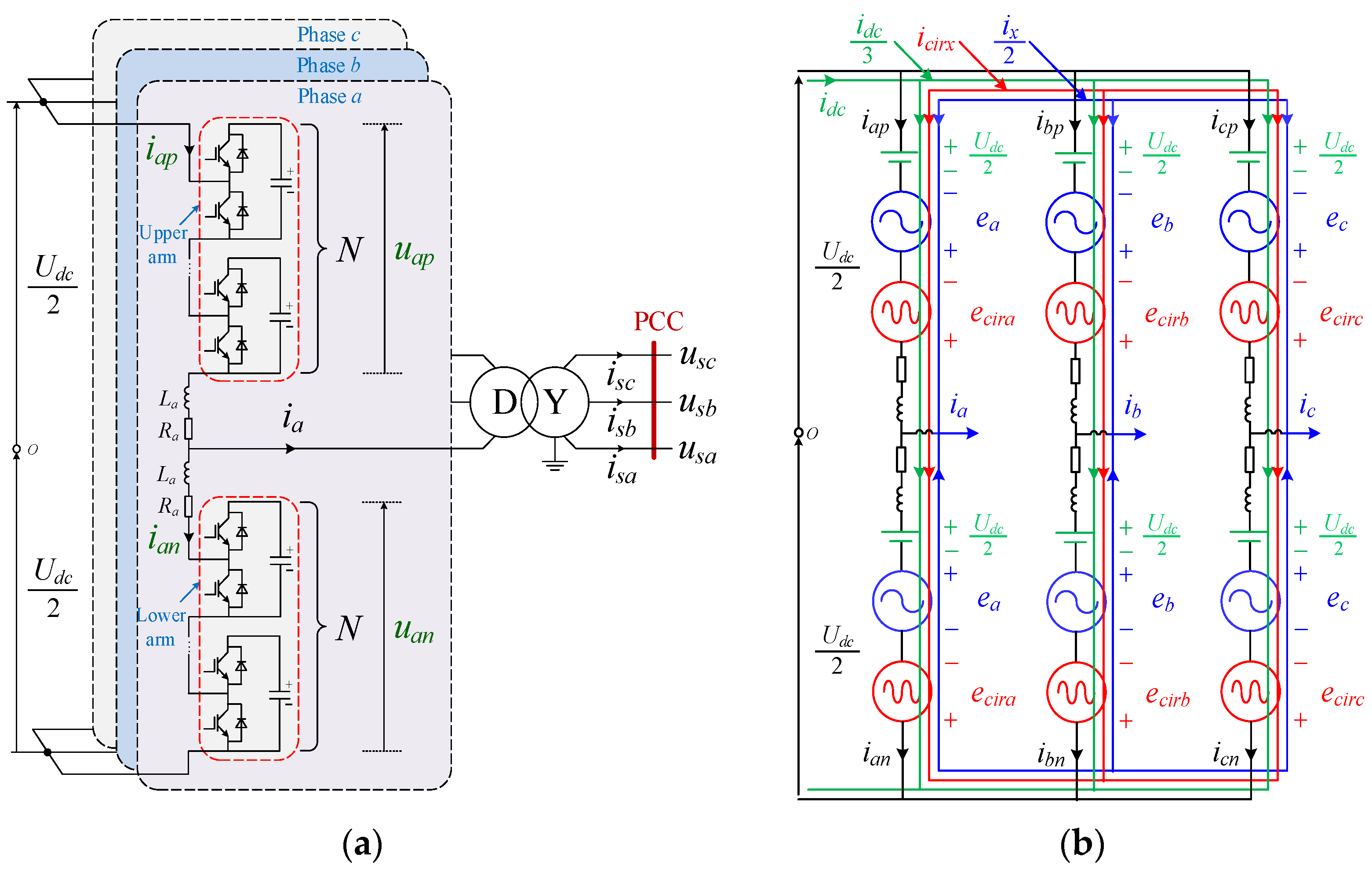
Figure 1. Block diagram of the MMC: (a) circuit topology; (b) equivalent circuit.
Electronics 12 01695 g001
Figure 2. Schematic diagram of the arm current of the MMC with the CCEC scheme: (a) inverter mode; (b) rectifier mode.
Electronics 12 01695 g002
Figure 3. Schematic diagram of the arm current of the MMC using the CCIC scheme in the inverter mode: (a) single injection of SOCC; (b) joint injection of SOCC and FOCC.
Electronics 12 01695 g003
Figure 4. Schematic diagram of the arm current of the MMC with the MCCIC scheme in the rectifier mode.
Electronics 12 01695 g004
Figure 5. Values of ηI and ηP with the variation of α: (a) ηI; (b) ηP.
Electronics 12 01695 g005
Figure 6. Values of ηL with different power levels.
Electronics 12 01695 g006
Figure 8. Simulation waveforms of the MMC operating in the inverter mode before and after using the proposed MCCIC strategy.
Electronics 12 01695 g008
Figure 9. Simulation waveforms of the MMC operating in the rectifier mode before and after using the proposed MCCIC strategy.
Electronics 12 01695 g009
Figure 11. Simulation waveforms of the overload performance of the MMC.
Electronics 12 01695 g011
Figure 12. The experimental platform of the studied MMC system.
Electronics 12 01695 g012
Figure 14. Experimental waveforms of the overload performance of the MMC using the proposed strategy.
Electronics 12 01695 g014
Table 1. Simulation parameters of the MMC system.
ParametersSimplesValuesUnits
Rated apparent powerSN1680MVA
Rated active powerPN1500MW
Rated reactive powerQN750MVar
Rated DC bus voltageUdcN500kV
Grid voltage (L-L)UmN230kV
Rated frequencyf50Hz
Transformer ratiokT230/260/
Transformer leakage inductanceLT0.15pu
Number of submodules per armN250/
Submodule capacitanceC20mF
Arm inductanceLa30mH
Grid inductanceLg40mH
Table 2. Comparisons between the theoretical values and the simulation results of the arm currents.
Inverter ModeRectifier Mode
CCECMCCICCCECMCCIC
IE (kA)3.63/−3.4/
3.69/−3.3/
IA (kA)/2.78/−2.57
/2.83/−2.54
IB (kA)/−2.48/2.15
/−2.42/2.17
IC(D) (kA)/2.78/−2.56
/2.83/−2.54
Disclaimer/Publisher’s Note: The statements, opinions and data contained in all publications are solely those of the individual author(s) and contributor(s) and not of MDPI and/or the editor(s). MDPI and/or the editor(s) disclaim responsibility for any injury to people or property resulting from any ideas, methods, instructions or products referred to in the content.