Abstract
Wind power generation has undergone significant development in recent decades due to its environmental advantages and its economic competitiveness. However, its increasing level of penetration is not exempt from drawbacks, such as those derived from the fluctuating nature of the wind. To reduce its negative incidence on grid power quality and stability, different techniques have been developed, such as those based on power smoothing. In these techniques, there is a research gap on the adjustment of the time constant that adapts to the needs of the smoothing, avoiding uncertain results, computational efforts and delays in the response of the control. This paper addresses the problem, proposing a novel method for power smoothing in a wind turbine by using a fuzzy-logic-based supercapacitor storage system and time-constant fitting, with a first-order adaptive transfer function. The method considers as input variables the active power generated by the wind turbine and the state of charge of the supercapacitor, both sampled simultaneously. After a computation process, the proposal generates active power set-point values that the supercapacitor must produce to compensate for the intermittency of the wind, seen from the point of connection to the grid. The results were validated experimentally with comprehensive laboratory tests.
1. Introduction
Bulk power systems (BPSs) comprising renewable energy are extensively interconnected to deliver power to loads economically and reliably. The improvement in power quality increases service continuity and reduces power outages and blackouts [1]. Among the sources with the highest growth in recent decades is wind energy. Due to fluctuation and intermittency of wind, the stability of highly wind-penetrated BPSs is becoming concerning, turning it into a critical factor affecting the safe and stable operation of the power system [2]. The variability of wind causes voltage and power fluctuations, which negatively affects power quality. In weak and isolated electrical systems, these problems can become even more critical [3]. Therefore, it is necessary to smooth and control the power generated from intermittent resources before injecting it into the grid [4]. Energy storage systems (ESSs) provide a promising solution to address power fluctuations caused by wind turbine generators (WTGs) [5]. The substantial advances in ESSs, as well as the reduction in costs, have promoted the application of these systems to reduce power fluctuations in renewable systems [6]. The ESSs are capable of smoothing the power fluctuations of wind turbines (WTs), controlling frequency and voltage deviations in low voltage networks. There are several types of ESSs that can be applicable for power smoothing, supercapacitors (SCs) being a promising technology to reduce fluctuations due to their high power density [7]. On the other hand, a battery energy storage system (BESS) can increase the efficiency of the system due to its high energy density. In this case, the power must be distributed between the BESS and the SC: the SC supplies the power peaks with high frequency fluctuations, and the BESS compensates the rest. Thus, the BESS lifespan is not compromised, and self-consumption increases [8]. However, to obtain adequate performance, non-trivial control of the power of the ESSs and simultaneous management of their states of charge (SOCs) are needed.
In the literature, several investigations have studied power smoothing methods that use ESSs to mitigate wind turbine (WT) power fluctuations. Generally, the algorithms for smoothing the output power of a WT are classified into direct and indirect controls [9].
The former include pitch-angle control, DC-link voltage control and rotor kinetic-energy control [10]. The pitch-angle control adjusts the orientation of blades for varying the output power of the WT [11], but this adjustment produces mechanical stress, shortening the blades’ lifespan and reducing the efficiency of energy conversion, and has a slow control response [12]. Despite the problems, pitch control is well developed and attracts interest by virtue of its WT power smoothing capability. In [13], a power smoothing method for a wind energy pitch-angle controller using advanced fuzzy logic is presented. The results were compared with a conventional method of power smoothing (exponential moving average), where the fuzzy logic controller considerably outperformed it. The control of rotor kinetic energy varies the acceleration and deceleration of the WT to absorb or release power from the rotating masses [14]. Under this type of control, the variation of the rotor range can lead to loss of stability in the electrical grid, and the WT starts operating at a non-optimal point, reducing the energy productivity of the wind farm [15]. The DC-link voltage control uses the energy storage capacity of the electronic converter’s DC-link capacitor for power smoothing [16]. However, the DC-link voltage control is considered an auxiliary method due to its energy limitations and is used in combination with the control of pitch angle or the control of rotor kinetic energy.
On the other hand, indirect power smoothing methods include the addition of ESSs as batteries [17], supercapacitors [18] or hybrid ESSs [19]. In this sense, Ref. [8] presents a novel method to determine the reference powers of a SC and a BESS through an adaptive low-pass filter. The computational results show that the proposed method reduces 92.6% of non-beneficial charge/discharge cycles of the BESS compared to a constant cut-off frequency filter. Researchers have presented methods based on fuzzy logic compared to conventional power smoothing methods, showing that the latter reduce delays caused by the uncertainty of power fluctuations of renewables. In addition, recent works have combined direct and indirect methods. For example, [20] presents energy management and control for a doubly fed induction generator (DFIG)-based wind turbine and a BESS via the DC-link of the back-to-back converter. The results show that the power sent to the grid by the converter is effectively smoothed by approximately 22% of its real value by applying fuzzy logic control. In addition, in [7], control with fuzzy logic is presented for a WT using SC. The fuzzy system is designed to smooth out wind power fluctuations and control the SOC of the SC. The proposed method is compared with conventional techniques, and the results show that fuzzy logic control improves power smoothing by optimally managing the SOC of the SC. On the other hand, supercapacitors have recently been applied to smooth power spikes in the framework of hybrid electric aircraft. In Ref. [21] the authors present energy control to improve energy management onboard Iron Bird and based on the elimination of overload capabilities. The results show that the fix has been verified and is currently in the hardware testing phase. Likewise, Ref. [22] presents a reduction in efforts in electric generators during the actuation of electromechanical actuators in the aeronautical industry using supercapacitors, and the results through simulations have demonstrated the effectiveness of the proposed control strategy.
In the cited studies, the authors have presented fuzzy-logic-based power smoothing methods and have outperformed conventional methods such as pitch-angle control and slow-response rotor kinetic-energy control. Regarding the use of ESSs to provide power smoothing, the most common technique is the use of a first-order low-pass filter with a fixed time constant to generate the expected smoothed power signal. Nevertheless, to improve smoothing, the time constant is varied in [23], and the moving average method is used to adjust it. This procedure requires high computational effort, reducing the effectiveness of the low-pass filter. In Refs. [24,25,26,27,28], different methods for adjusting the time constant of wind turbines using fuzzy logic are presented. However, the authors in these articles calculated the time constant by trial and error, without an in-depth study, leaving a gap in research that must be filled. This is the adjustment of the time constant that adapts to the needs of the smoothing, avoiding uncertain results, computational efforts and delays in the response of the control. This paper presents a novel power smoothing method for a WT through the use of storage system (a SC–ESS) based on fuzzy logic and time constant setting using an adaptive first-order transfer function. The method takes as input variables the active power generated by the WT and the state of charge of the SC–ESS, both sampled simultaneously. After a computation process, the proposal generates active power set-point values that the SC–ESS must produce to compensate for wind intermittency, seen from the point of connection to the grid. In summary, the main contributions of the paper are detailed below:
- A novel power smoothing technique based on an adaptive first-order transfer function, whose time constant is adjusted in real time and adapted to the smoothing needs. This adjustment is governed by a fuzzy logic controller (FLC).
- The FLC designed to generate variable time constants modifies the time constant in real time, improving power smoothing using real ramp rate of the active power to be smoothed and the state of charge (SOC) of the energy storage agent used. Its use combined with the adaptive transfer function improves existing methods.
- The rules introduced in the FLC aim to refine the power smoothing while respecting the lower and upper limits of the SOC of the energy storage agent.
- Preliminarily, the proposed method is evaluated in a computer simulation environment (MATLAB/Simulink®).
- To validate the simulation results of the novel proposed power smoothing method, comprehensive laboratory tests were carried out.
2. Power System Modeling
2.1. Modeling of Variable-Speed Wind Turbine
Figure 1 shows the simplified model of a variable-speed wind turbine (VSWT), proposed by the authors in Ref. [29], which was used in this research. In the diagram of Figure 1, Tt and Tem are the mechanical and electromagnetic torque, respectively. PWT is the total output active power, t and ωg are the angular speed of the WT and electric generator and v and β denote the wind speed and the pitch angle, respectively. The operation of the control system shown in Figure 1 was successfully validated by simulation in [30]. As demonstrated in Ref. [31], this system incorporates the representation of the power converter with two closed-loop controllers that regulate the power flow sent to the grid. In this simplified approach, the dynamics of the power electronics converter and the generator of a VSWT are represented by a first-order function with time constants and , respectively. The selection of the numerical values of and depends on the actual commercial model to be represented. For this study, the values provided by the researchers in [32] were taken as a reference.
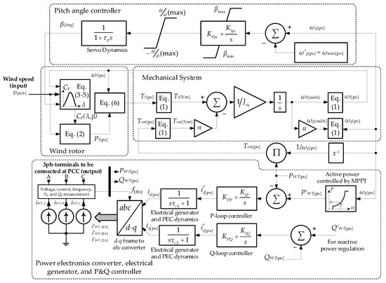
Figure 1.
Representative diagram of the simplified model VSWT.
The mathematical formulation of the components of the proposed model is detailed below:
The group of Equation (1) calculates the variables represented in the mechanical system of VSWT model.
where , and represent power, torque and angular speed, respectively; p and n are the pole pairs of the generator and the gearbox ratio, respectively. Subscripts g and denote the generator and turbine variables, respectively. Subscript “base” refers to the base value of variables for per unit calculation.
Equations (2)–(6) represent the power and dynamic conditions of the WT [30]:
where is the mechanical power delivered by the wind rotor, , and represent power coefficient, rotor radius and air density, respectively; is the tip speed ratio; is a shape factor that depends on and ; and are the power and speed constants, respectively; and constants are approximations of the power coefficient for the three-blade WT based on factory specifications and are explained in detail in Refs. [33,34]. The maximum power point tracking (MPPT) algorithm to extract the maximum power from VSWT is expressed in Equation (7), where is the optimization constant that depends on the constructive features of turbine [29]. It is important to note that Equation (7) is derived from (2) but with the incorporation of restrictions that guarantee the operation of the VSWT within its mechanical and thermal limits in the face of wind speed variability. These constraints are: (a) a smooth and linear start of the machine for low speeds in the rotor speed range (under light winds), (b) an optimal MPPT power dispatch within the speed range (under nominal winds) and (c) a smooth and safe ride towards the maximum value of power admissible by the VSWT (normally, the rated power), when the machine operates at high speeds: (under strong winds). The numerical values of all the parameters defined up to here are provided in Appendix A.
The power electronics converter (PEC) has been developed in previous works [31]. The PEC was modeled using a controlled three-phase current source. The current source injects a three-phase current , and where the amplitude and phase of each component depend on the control criteria implemented and assigned to the PEC converter.
The PI closed-loop controller is applied to control the active power of the WT, generating the output signal as shown in Equation (8). To represent the controller time, a first-order delay function is applied .
The reactive power control uses the controllable variable as shown in Equation (9).
The Park transform is used to obtain the variables ( and ) in real time as shown in Equation (10). To provide feedback to the PI controllers, the powers P and Q are measured. The output variables are , and , as represented in Figure 1. The detail of the model was developed in [31].
where is the angular frequency of the grid voltage at Point of Common Coupling (PCC); and are the homopolar, quadrature and direct components, respectively; and , and are three-phase current.
2.2. Wind Turbine Connected to the Grid
Figure 2 shows the VSWT connected to the grid. It is composed of a WT rotor; a pitch-angle controller; a machine side converter (MSC) and a grid side converter (GSC), represented as a whole PEC in this work; an electric generator governed by the MSC under MPPT criteria and a GSC controller.
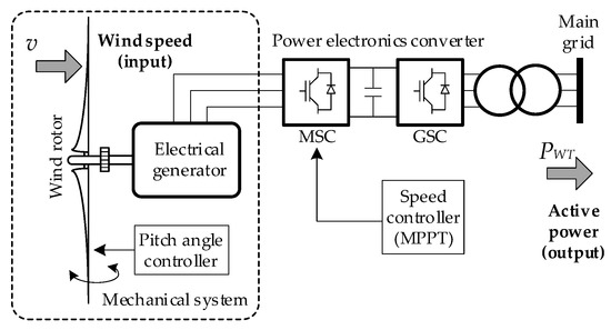
Figure 2.
VSWT model connected to the grid.
3. Proposed Control Strategy
The proposed control strategy is applied to a supercapacitor-based energy storage system (SC–ESS) connected to the grid through a bidirectional power inverter. This inverter enables the SC–ESS to freely control the injection and absorption of active and reactive power in the PCC depending on the availability of the electrostatic energy stored in the upstream bank of capacitors (SOC). In this study, controlled conditions were defined to facilitate the evaluation of the effectiveness of the proposal (Figure 3). The main grid is taken as a BPS; therefore, it is represented by an ideal three-phase voltage source. The objective of the proposed controller system is to smooth the power fluctuations of VSWT, PWT, by regulating the power injection/absorption from the SC–ESS, PSC, such that, in the PCC, a smother injection of wind power is perceived, PT.
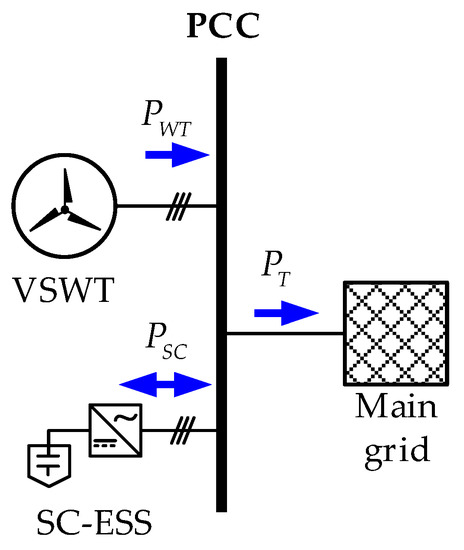
Figure 3.
Single-line diagram of the power system under study.
Figure 4 shows the general block diagram of the proposed controller. The algorithm takes as input the measurement of active power injected by the WT in per unit, PWT. This signal is applied, firstly, to the varying transfer function block, whose purpose is to generate a desired smoothed power profile, PSMTD, which must be achieved through controlled power injection by the SC–ESS, P*SC. This transfer function has a dynamic time constant which must be adjusted according to the real needs of smoothing and, with this, helps to improve performance in smoothing tasks. The time constant is calculated and updated in real time by a fuzzy logic controller (FLC), which generates a control signal x that obeys a series of rules imposed by the current state of the input variables dPWT/dt and SOC. The first variable corresponds to the temporary rate of change of the injected wind power (a measurement of the degree of its variability), and the second one is the state of charge of the storage system. The design and operation of the FLC are described in Section 3.2.
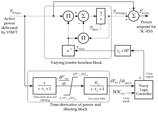
Figure 4.
Overall diagram of the proposed controller.
Now, to generate the dPWT/dt signal and make it suitable for this application, the control scheme takes the PWT signal and applies it to a time-derivative of power and the filtering block. In this block, τ1 and τ2 are the time constants of the filters used, and K1 is a design constant. Finally, to avoid an overflow in the first step of calculating the numerical derivative, a saturation characteristic is added between the two blocks that keeps this variable between the upper and lower limit values: . The numerical values assigned to these parameters can be found in Appendix B.
3.1. Varying Transfer Function
Figure 5 shows a simplistic representation of the developed varying transfer function block. The block consists of a first-order low-pass filter with adaptive time constant τx. The intermittent wind power signal, PWT, is applied to this block to obtain the expected smoothed power, PSMTD. For the purposes of this research, the time constant was designed so that it offers a numerical variation around the value of a fixed time constant, τ0. Thus, the input variable, x, can be modified in a range of numerical values greater than or equal to zero in order to produce a multiplier effect in base-10 at the fixed time constant, as expressed in Equation (11). Additionally, this block can be loaded with an initial output condition, P0, if the control objectives so require. The implementation of this block is presented in the upper subsystem of the general scheme of Figure 4, and the numerical values assigned to its parameters can be consulted in the Appendix A.
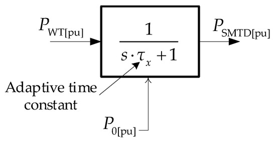
Figure 5.
Varying transfer function block.
3.2. Fuzzy Logic Controller (Structure and Design)
By adjusting the time constant (τx), the controller is able to fully charge/discharge the SC, thus improving the power smoothing effect. This paper presents the fuzzy logic controller (FLC) based on the centroid interference method shown in Figure 6. The proposed FLC has two inputs and one output. The inputs correspond to the fuzzification process and the output to the defuzzification process after applying the fuzzy rules:
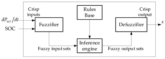
Figure 6.
Schematic representation of the fuzzy logic controller.
- Input 1: The time derivative of the active power of VSWT indicates the power ramp rate and generates the reference signal for SC–ESS related to the adaptive first-order transfer function.
- Input 2: The SOC reflects whether the SC is charging (discharging) or not.
- Output: Smoothing factor (x) is adjusted according to the smoothing requirements defined by and the available energy in the SC.
The time constant is adjusted by applying fuzzy logic through the smoothing factor to optimize the state of charge of the SC in real time. Until now, there has been no description in the literature for the determination of its value by relating it to the active power of VSWT and state of charge of the SC in real time. This paper provides a heuristic method to determine it.
On the other hand, Figure 7 shows the membership functions of the FLC. The controller adjusts the time constant at each instant according to the variation in wind power and the SOC of the SC–ESS. Robust mathematics is required to establish the membership functions. An effective way to determine them is presented in the study carried out by the authors in Ref. [35]. For the design of fuzzy values, triangular and trapezoidal group membership functions are used. Table 1 shows the control rules for the strategy proposed in this paper. Finally, the centroid method is used for defuzzification.
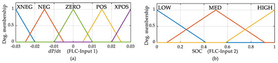
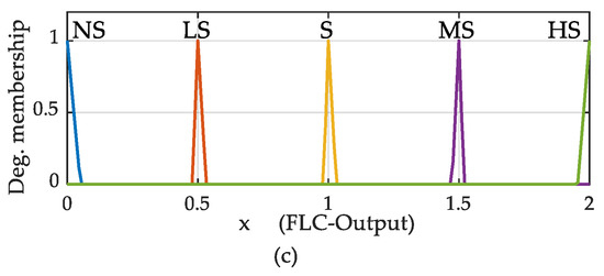
Figure 7.
Membership functions of the FLC proposed: (a) input 1: , (b) input 2: SOC and (c) output: smoothing factor x. NS = no smoothing, LS = little smoothing, S = smoothing, MS = moderate smoothing, HS = high smoothing. Values of input 1: XNEG = extra negative, NEG = negative ZERO = zero POS = positive, XPOS = extra positive. Values of input 2: low = 0%, med = 50%, high =100%.

Table 1.
Fuzzy rules.
By evaluating the FLC, it is possible to determine the variation of the two inputs and the output of the control system. Figure 8 shows the resulting surface:
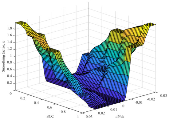
Figure 8.
Input and output of the designed FLC.
4. Simulation, Experimentation and Results
The system under study in this paper includes a VSWT subjected to a variable wind regime connected in parallel to the SC. These two components are connected to the main grid (infinite power bus) as shown in Figure 3.
4.1. Computer Simulation Results
Firstly, the operation of the proposed control is validated in a computer simulation environment. For this, the models shown in Figure 1 and Figure 2 were used. The input variables for the simulations are a real wind profile with high variability of 400 s time horizon as shown in Figure 9. This record is from measurements taken at San Cristóbal wind farm (0°53′31.4″ S 89°29′56.2″ W, Galápagos-Ecuador) on 4 August 2015 at 51 m above the ground. The VSWT power output for this wind profile, computed with the mathematical models described, is shown in Figure 10.
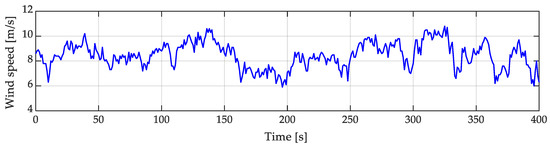
Figure 9.
Wind profile introduced to the VSWT model.
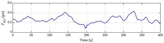
Figure 10.
Wind power output from the VSWT model.
The proposed model was simulated in MATLAB/Simulink. Figure 11 shows the two input variables and the output variable when applying the FLC, satisfying the fuzzy rules. The dPWT/dt dynamics in Figure 11a register positive and negative values according to the real variability of the wind power and is free of noise, which certifies a correct operation of the lower subsystem of Figure 4 and the calculation of the first FLC input signal.
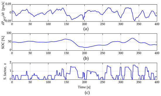
Figure 11.
Input and output variables to the fuzzy logic controller. (a) dPWT/dt dynamics, (b) state of charge of the SC–ESS and (c) adjusting of the smoothing factor in real time.
Then, in Figure 11b the behavior of the SOC of the SC–ESS is observed. In the simulation, this dynamics was approximated by time-integration of the variable PSC (Figure 12) and applied as a second input signal to the FLC. In practice, this signal is accurately provided by the battery management system (BMS) of the SC–ESS. Finally, Figure 11c shows the resulting smoothing factor, x, at the FLC output. A close view of the latter plot shows correct compliance with the fuzzy rules established in Table 1 and illustrated in Figure 8.
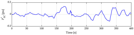
Figure 12.
Power set-point generated by the algorithm that serves as the command for the SC–ESS to smooth the wind power.
According to the scheme shown in Figure 4, the proposed control system generates the set-point power for the SC–ESS to achieve the power smoothing from the utility grid perspective.
Finally, it is evident in Figure 13 that the power injected to the system, PT, is smoothed compared to the one with no smoothing. Then, the power fluctuations are flattened by reducing the power peaks and displacing them in certain cases; this effect depends on the state of charge of the SC and the decision of the controller. It is important to note that the proposed control system avoids peaks and valleys in the power curve.
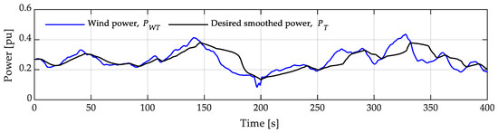
Figure 13.
Wind power generated by the VSWT and the expected resulting power with the application of the proposed algorithm.
4.2. Experimental Results
To validate the proposed control system, comprehensive laboratory experiments were performed in the test bench of the Microgrid Laboratory of the University of Cuenca, Ecuador [36]. The implementation scheme is shown in Figure 14. There, the wind power profile that is injected into the grid by the VSWT is emulated by a 50 kW lithium-ion BESS. For this, the real wind speed record of Figure 9 was taken and applied to the VSWT-model (Figure 1) and implemented and executed in MATLAB/Simulink. The output of this model provides, among others, the set-point P*WT, which is applied every 100 milliseconds to the lithium-ion BESS through microgrid control SCADA system. In parallel, the proposed control algorithm is implemented in a MATLAB script and run. The 30 kW SC–ESS unit exists in the laboratory (not emulated), is connected to the PCC and its inverter is in communication with the SCADA. The proposed control loop was designed so that the action of reading input data via SCADA (PWT, and SOC of SC–ESS) and the execution of the algorithm guarantee the writing of the P*SC variable in the 30 kW SC–ESS bidirectional power electronics converter (PEC) every 100 milliseconds. To achieve this computation time, it was necessary to implement the fuzzy logic controller (Figure 8) through a look-up table in the script. More technical details of the actual equipment lithium-ion BESS-50 kW (used for wind turbine emulation) and 30 kW SC–ESS used in the laboratory are provided in Appendix C.
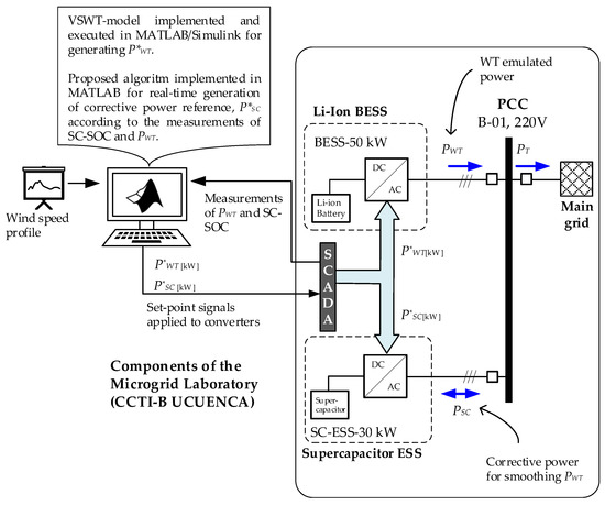
Figure 14.
Implementation of the test bench in the laboratory.
The following figures show the results obtained experimentally. For comparison purposes, the active power signals, PWT, achieved with the Li-Ion-BESS (50 kW) and, PSC, produced by the SC–ESS (30 kW), are expressed in per unit. The wind power output from the laboratory for the wind profile of Figure 9 is shown in Figure 15. As can be seen, the waveform resembles the result of the simulations (Figure 10).
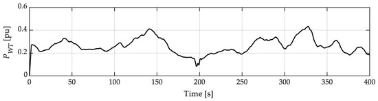
Figure 15.
Emulated wind generation in the laboratory.
The output of the proposed control generates the reference for SC–ESS, which is achieved by the actual SC–ESS unit in the laboratory (Figure 16a). Where the SC is subjected to different charge/discharge cycles depending on the unsmoothed VSWT power curve and the controller, it is evident in Figure 16b that the SOC levels of the SC–ESS remain within secure values (within the 10–90% for the real SC–ESS prototype). The proposed algorithm is implemented and run in MATLAB in real time to generate the reference signal of the energy storage system of the SC–ESS. The SC–ESS receives an active power command generated by the algorithm implemented in the SCADA every 100 milliseconds, as mentioned. Finally, Figure 16c shows the dynamics of the DC voltage at different stages of the SC–ESS: at the terminals of the supercapacitor bank (dashed line) and the DC-bus at the output of the boost converter upstream in the three-phase inverter (continuous line).
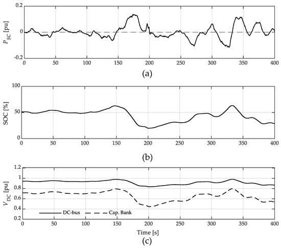
Figure 16.
Response of the supercapacitors (SC–ESS) to power fluctuations in Figure 15: (a) Active power delivered by the SC–ESS converters, (b) evolution of the state of charge of the SC–ESS during smoothing and (c) DC voltage of the supercapacitor array upstream of the inverter.
As expected, in Figure 13, the result of the proposed control system effectively reduces the VSWT fluctuations. In this case, Figure 17 shows the effectiveness of the method when comparing the original injected wind power and the combined effect of this with the power provided by the SC–ESS. The dynamics of the resulting active power injected into the grid (PWT + PSC = PT) show the effectiveness in the smoothing tasks. In this case, a smoothing of 22% is achieved (i.e., the variance of the compared time series is reduced by 22%). It is important to mention that, for the laboratory experiment, an initial time constant of τ0 = 0.5 s was assigned to the algorithm (Figure 4) to avoid rapid discharge of the SC–ESS. However, it has been shown both in simulation and in experimental tests that larger values of this parameter, for example τ0 = 2.0 s, can improve the effectiveness of smoothing tasks.
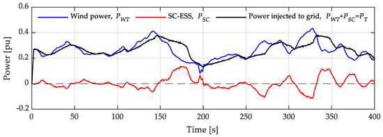
Figure 17.
Experimental results, original injected wind power (blue), power delivered by SC–ESS (red), combined wind-supercapacitors effect with the smoothing algorithm (black).
In order to evaluate the effectiveness of the proposal under extreme conditions of the charge level of the SC–ESS, two additional tests were carried out: overcharged and undercharged. The experimental results, summarized in Figure 18 and Figure 19, show the performance of the proposed method in these cases.
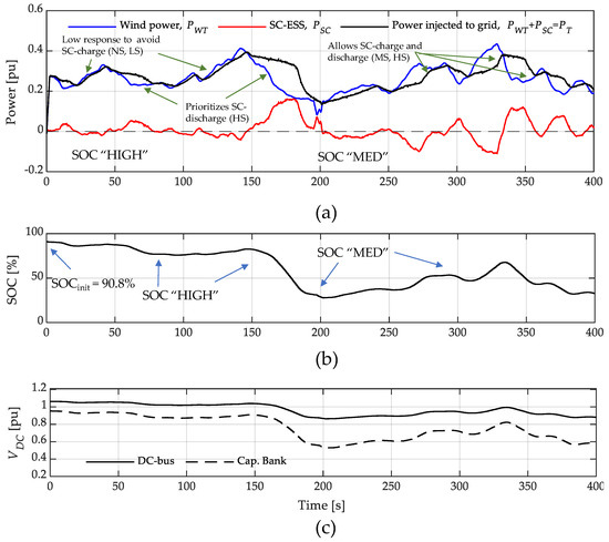
Figure 18.
Experimental results in SC–ESS overcharge condition: (a) original injected wind power (blue), power delivered by SC–ESS (red), combined wind-supercapacitors effect with the smoothing algorithm (black); (b) evolution of SOC; (c) DC voltage of the supercapacitor array upstream of the inverter.
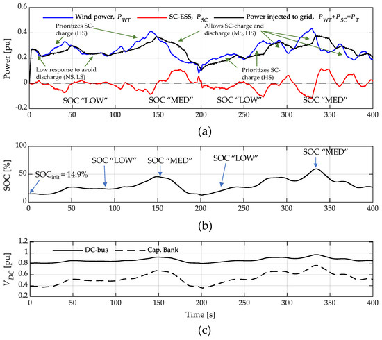
Figure 19.
Experimental results in SC–ESS undercharge condition: (a) original injected wind power (blue), power delivered by SC–ESS (red), combined wind-supercapacitors effect with the smoothing algorithm (black); (b) evolution of SOC; (c) DC voltage of the supercapacitor array upstream of the inverter.
To evaluate the proposal’s effectiveness with the overcharged condition, the SC–ESS was prepared with an initial state of charge of 90%. Now, according to the fuzzy rules of Table 1, when the SOC has “HIGH” levels, the proposed method proceeds to smooth the wind power prioritizing the discharge of the SC–ESS by responding strongly to negative slope wind power (dPWT/dt < 0): high smoothing (HS) and moderate smoothing (MS). On the contrary, when dPWT/dt > 0, the SC–ESS responds weakly to limit its recharge and move it away from the overcharge condition: little smoothing (LS) and no smoothing (NS). Then, as the SOC decreases to a medium level, “MED”, the degree of smoothing equalizes for both positive and negative sloped wind power variations (Figure 18a), substantially improving smoothing tasks. Finally, when the SOC reaches its “LOW” value, the method forces the SC–ESS to prioritize its charge instead of its discharge, reducing the effectiveness of the smoothing when dPWT/dt < 0 (LS and NS) and boosting it when dPWT/dt > 0 (MS and HS). Response of the SC–ESS dependent on the level of the SOC and the variability of the power to be smoothed (dPWT/dt) guarantees the effectiveness in power smoothing while maintaining the volatile SOC of an SC–ESS within safe operating limits. In this first case, a smoothing of 16% is achieved. Similar reasoning can be applied to explain the test in the undercharged condition (initial SOC of 15%), whose results are shown in Figure 19. In this case, a smoothing of 24% is obtained.
5. Conclusions
This paper presents a novel power smoothing method for a wind turbine (WT) by using a storage system (SC–ESS) based on fuzzy logic and time-constant fitting using an adaptive first-order transfer function. The new proposed method considers as input variables the active power generated by a WT and the state of charge of the SC–ESS, both sampled simultaneously. After a computation process, the proposal generates active power set-point values that the SC–ESS must produce to compensate for the intermittency of the wind seen from the point of connection to the grid.
The transfer function has a dynamic time constant which must be adjusted according to the real needs of smoothing and, with this, helps to improve performance in smoothing. The time constant is calculated and updated in real time by a fuzzy logic controller, which generates a control signal, x, which follows a series of rules imposed by the current state of the input variables dPWT/dt and SOC. Furthermore, the method includes a simplified modeling of the WT presented by the authors in previous studies.
The effectiveness of the method was evaluated in MATLAB/Simulink® and validated with extensive laboratory tests.
When applying the fuzzy rules, the dynamics of the variation of the active power of the WT with respect to time, positive and negative values are registered according to the real variability of the wind power, and it is free of noise, which ensures the correct operation of the subsystem.
The blended active power injected by the WT and the SC into the grid shows the effectiveness in the power smoothing tasks. In this case, a smoothing of 22% is achieved. It is important to mention that, for the laboratory experiment, an initial low value of the fixed time constant, τ0, was assigned to the algorithm so as to avoid rapid discharge of the SC–ESS. However, after several trial-and-error tests in simulation, it was found that a higher value of τ0 allows better performance in smoothing tasks without compromising the secure levels of SOC, even when the SC–ESS was subjected to extreme SOC conditions: overcharged and undercharged. This was verified in the experimental tests.
Since an optimal selection of parameter τ0 depends on the type of electrical system with which intermittent wind generation is integrated, a more in-depth study is necessary in this regard.
Author Contributions
Conceptualization, D.O. and S.M.; Data curation, D.O.; Formal analysis, P.A., D.O. and S.M.; Funding acquisition, S.M.; Investigation, P.A.; Methodology, P.A.; Project administration, D.O.; Resources, D.O.; Software, D.O.; Supervision, D.O. and S.M.; Validation, D.O.; Visualization, S.M.; Writing—original draft, P.A.; Writing—review and editing, P.A., D.O. and S.M. All authors have read and agreed to the published version of the manuscript.
Funding
Part of the work documented in this manuscript is part of the activities carried out in the project entitled: “Movilidad Eléctrica: retos, limitaciones y plan de implementación en el régimen especial de la Provincia de Galápagos enfocada en el desarrollo sostenible y su factibilidad en la Ciudad de Cuenca”, II Concurso de Proyectos de Investigación—Vinculación, Vicerrectorado de Investigación y la Dirección de Vinculación con la Sociedad de la Universidad de Cuenca. This project is currently co-directed by the author Danny Ochoa. Part of the research described in this work was funded by the Spanish national research agency Agencia Estatal de Investigación, grant number PID2019-108966RB-I00 /AEI/ 10.13039/501100011033.
Data Availability Statement
Data will be made available on request.
Acknowledgments
The author Paul Arévalo thanks the Call for Grants for the Requalification of the Spanish University System for 2021–2023, Margarita Salas Grants for the training of young doctors awarded by the Ministry of Universities and financed by the European Union—NextGeneration EU. Finally, the authors thank Universidad de Cuenca for easing access to the facilities of the Microgrid Laboratory of the Centro Científico Tecnológico y de Investigación Balzay (CCTI-B), for allowing the use of its equipment and for authorizing members of its staff (Edisson Villa and Vinicio Iñiguez) for the provision of technical support necessary to carry out the experiments described in this article.
Conflicts of Interest
The authors declare no conflict of interest.
Appendix A
Appendix A.1. Extended VSWT-Model Parameters
Table A1.
Wind turbine parameters.
Table A1.
Wind turbine parameters.
| Parameter | Symbol | Value and Units |
|---|---|---|
| Base power | 1.5 MW | |
| Max./Min. power of the generator | 1, 0.04 pu | |
| Max./Min. torque of the generator | 0.826, 0.057 pu | |
| Wind speed at | 12 m/s | |
| Number of pole pairs | 2 | |
| Gearbox ratio | n | 1 (No gearbox in full converter VSWT) |
| Nominal frequency | 60 Hz | |
| Base speed of the turbine | 1.644 rad/s | |
| Base speed of the generator | 1.644 rad/s | |
| Air density | 1.225 kg/m3 | |
| Radius of the rotor | 38.5 m | |
| Power constant | ||
| Speed constant | 63.29 m/s | |
| Min./Max. blade pitch angle | 0°, 45° | |
| Maximum blade pitch-angle rate | 2°/s | |
| Turbine-generator inertia constant | 5.29 s | |
| Blade pitch servo time constant | 0 s | |
| Pitch controller gains | 500, 0 | |
| Speed controller gains | 0.3, 8 | |
| PEC active power PI controller | 5, 50 | |
| PEC active power PI controller | −5, −50 | |
| PEC time constant | 20 ms |
Appendix A.2. MPPT-Curve Parameters
Appendix A.3. Utility Grid Parameters (Simulation and Laboratory)
Appendix B
Table A2.
Parameters of proposed controller.
Table A2.
Parameters of proposed controller.
| Parameter | Symbol | Value and Units |
|---|---|---|
| Fixed time constant | 2.0 s | |
| Initial output power | 0 pu | |
| Time derivative filtering block time constants | 0.1, 10 s | |
| Time derivative filtering block design gain | 5 | |
| Upper and lower limit for the numerical calculation | ±0.05 pu/s |
Appendix C
Appendix C.1. Description of Lithium-Ion BESS-50 kW Used in Laboratory for VSWT Emulation
The lithium-ion battery bank of the micro-grid lab is made up of 11 cells of 58.36 VDC, connected in series (model ELPT392-0002, Samsung). The output DC voltage of the bank is 642 V, with a power of 88 kW and an energy storage capacity of 44 kWh. The bank is connected to a 50 kW power electronics converter for its connection to the AC-grid (see Figure A1).

Figure A1.
Lithium-ion BESS from the micro-grid laboratory: cell bank (left), power electronics converter cabinet (right).
Figure A1.
Lithium-ion BESS from the micro-grid laboratory: cell bank (left), power electronics converter cabinet (right).

Appendix C.2. Description of SC–ESS-30 kW Used in Laboratory for Power Smoothing
In the micro-grid lab, there is a supercapacitor bank with 10 electric double-layer capacitors (EDLCs) connected in series, 130 F and 56 VDC each (BOOSTCAP model BMOD0130, from Maxwell Technologies (see Figure A2)). The bank’s terminal DC voltage is 560 V, and its total energy storage capacity is 0.57 kWh. The bank delivers its energy to the AC-grid through a 30 kW power electronics converter formed by a DC boost converter and a bidirectional three-phase inverter.

Figure A2.
SC–ESS from the micro-grid laboratory: bank of supercapacitors (left), cabinet containing the power electronics converter (right).
Figure A2.
SC–ESS from the micro-grid laboratory: bank of supercapacitors (left), cabinet containing the power electronics converter (right).

References
- Imdadullah; Alamri, B.; Hossain, M.A.; Jamil Asghar, M.S. Electric Power Network Interconnection: A Review on Current Status, Future Prospects and Research Direction. Electronics 2021, 10, 2179. [Google Scholar] [CrossRef]
- Dai, J.; Wan, L.; Chang, P.; Liu, L.; Zhou, X. Reactive Voltage Control Strategy for PMSG-Based Wind Farm Considering Reactive Power Adequacy and Terminal Voltage Balance. Electronics 2022, 11, 1766. [Google Scholar] [CrossRef]
- Ochoa, D.; Martinez, S. Analytical Approach to Understanding the Effects of Implementing Fast-Frequency Response by Wind Turbines on the Short-Term Operation of Power Systems. Energies 2021, 14, 3660. [Google Scholar] [CrossRef]
- Atif, A.; Khalid, M. Fuzzy logic controller for solar power smoothing based on controlled battery energy storage and varying low pass filter. IET Renew. Power Gener. 2020, 14, 3824–3833. [Google Scholar] [CrossRef]
- Lamsal, D.; Sreeram, V.; Mishra, Y.; Kumar, D. Output power smoothing control approaches for wind and photovoltaic generation systems: A review. Renew. Sustain. Energy Rev. 2019, 113, 109245. [Google Scholar] [CrossRef]
- Zhou, Y.; Yan, Z.; Li, N. A Novel State of Charge Feedback Strategy in Wind Power Smoothing Based on Short-Term Forecast and Scenario Analysis. IEEE Trans. Sustain. Energy 2017, 8, 870–879. [Google Scholar] [CrossRef]
- de Carvalho, W.C.; Bataglioli, R.P.; Fernandes, R.A.S.; Coury, D.V. Fuzzy-based approach for power smoothing of a full-converter wind turbine generator using a supercapacitor energy storage. Electr. Power Syst. Res. 2020, 184, 106287. [Google Scholar] [CrossRef]
- Eydi, M.; Alishahi, M.; Zarif, M. A novel output power determination and power distribution of hybrid energy storage system for wind turbine power smoothing. IET Electr. Power Appl. 2022, 16, 1559–1575. [Google Scholar] [CrossRef]
- Zhu, Y.; Guo, Y.; Wang, Z.; Wei, Z. Kinetic energy based output power smoothing control and parameters design for PMSG-WECSs. Int. J. Electr. Power Energy Syst. 2021, 131, 107077. [Google Scholar] [CrossRef]
- Lyu, X.; Jia, Y.; Xu, Z. A novel control strategy for wind farm active power regulation considering wake interaction. IEEE Trans. Sustain. Energy 2020, 11, 618–628. [Google Scholar] [CrossRef]
- Čonka, Z.; Beňa, Ľ.; Štefko, R.; Pavlík, M.; Holcsik, P.; Pálfi, J. Wind Turbine Power Control According to EU Legislation. Energies 2022, 15, 8614. [Google Scholar] [CrossRef]
- Fan, Y.J.; Xu, H.T.; He, Z.Y. Smoothing the output power of a wind energy conversion system using a hybrid nonlinear pitch angle controller. Energy Explor. Exploit. 2022, 40, 539–553. [Google Scholar] [CrossRef]
- Naik, K.A.; Gupta, C.P.; Fernandez, E. Wind power smoothing in partial load region with advanced fuzzy-logic based pitch-angle controller. Wind Eng. 2022, 46, 52–68. [Google Scholar] [CrossRef]
- Liu, B.; Zhao, J.; Huang, Q.; Milano, F.; Zhang, Y.; Hu, W. Nonlinear Virtual Inertia Control of WTGs for Enhancing Primary Frequency Response and Suppressing Drivetrain Torsional Oscillations. IEEE Trans. Power Syst. 2021, 36, 4102–4113. [Google Scholar] [CrossRef]
- Tahir, K.; Allaoui, T.; Denai, M.; Mekhilef, S.; Belfedal, C.; Doumi, M. Second-order sliding mode control of wind turbines to enhance the fault-ride through capability under unbalanced grid faults. Int. J. Circuit Theory Appl. 2021, 49, 1959–1986. [Google Scholar] [CrossRef]
- Zhu, Y.; Ma, Z.; Wang, Z. An improved fuzzy logic based DC-link voltage control strategy for smoothing output power of the PMSG-WECS. Energy Rep. 2022, 8, 8413–8425. [Google Scholar] [CrossRef]
- Meng, J.; Wang, D.; Wang, Y.; Guo, F.; Yu, J. An improved damping adaptive grid-forming control for black start of permanent magnet synchronous generator wind turbines supported with battery energy storage system. IET Gener. Transm. Distrib. 2023, 17, 354–366. [Google Scholar] [CrossRef]
- Cano, A.; Arévalo, P.; Jurado, F. Evaluation of temporal resolution impact on power fluctuations and self-consumption for a hydrokinetic on grid system using supercapacitors. Renew. Energy 2022, 193, 843–856. [Google Scholar] [CrossRef]
- Benavides, D.; Arévalo, P.; Tostado-Véliz, M.; Vera, D.; Escamez, A.; Aguado, J.A.; Jurado, F. An Experimental Study of Power Smoothing Methods to Reduce Renewable Sources Fluctuations Using Supercapacitors and Lithium-Ion Batteries. Batteries 2022, 8, 228. [Google Scholar] [CrossRef]
- Nasef, S.A.; Hassan, A.A.; ElMadany, H.T.; Zahran, M.B.; El-Shaer, M.K.; Abdelaziz, A.Y. Optimal Power Management and Control of Hybrid Photovoltaic-Battery for Grid-Connected Doubly-Fed Induction Generator Based Wind Energy Conversion System. Int. J. Renew. Energy Res. 2022, 12, 408–421. [Google Scholar]
- Sumsurooah, S.; He, Y.; Torchio, M.; Kouramas, K.; Guida, B.; Cuomo, F.; Atkin, J.; Bozhko, S.; Renzetti, A.; Russo, A.; et al. ENIGMA—A Centralised Supervisory Controller for Enhanced Onboard Electrical Energy Management with Model in the Loop Demonstration. Energies 2021, 14, 5518. [Google Scholar] [CrossRef]
- Cavallo, A.; Russo, A.; Canciello, G. Control of supercapacitors for smooth EMA operations in aeronautical applications. Proc. Am. Control Conf. 2019, 2019, 4948–4954. [Google Scholar] [CrossRef]
- Jiang, Q.; Wang, H. Two-time-scale coordination control for a battery energy storage system to mitigate wind power fluctuations. IEEE Trans. Energy Convers. 2013, 28, 52–61. [Google Scholar] [CrossRef]
- Ochoa, D.; Martinez, S. Proposals for Enhancing Frequency Control in Weak and Isolated Power Systems: Application to the Wind-Diesel Power System of San Cristobal Island-Ecuador. Energies 2018, 11, 910. [Google Scholar] [CrossRef]
- Lin, X.; Lei, Y. Coordinated Control Strategies for SMES-Battery Hybrid Energy Storage Systems. IEEE Access 2017, 5, 23452–23465. [Google Scholar] [CrossRef]
- Lamsal, D.; Sreeram, V.; Mishra, Y.; Kumar, D. Smoothing control strategy of wind and photovoltaic output power fluctuation by considering the state of health of battery energy storage system. IET Renew. Power Gener. 2019, 13, 578–586. [Google Scholar] [CrossRef]
- Zhang, K.; Mao, C.; Lu, J.; Wang, D.; Chen, X.; Zhang, J. Optimal control of state-of-charge of superconducting magnetic energy storage for wind power system. IET Renew. Power Gener. 2014, 8, 58–66. [Google Scholar] [CrossRef]
- Li, X. Fuzzy adaptive Kalman filter for wind power output smoothing with battery energy storage system. IET Renew. Power Gener. 2012, 6, 340–347. [Google Scholar] [CrossRef]
- Ochoa, D.; Martinez, S.; Arévalo, P. Extended Simplified Electro-Mechanical Model of a Variable-Speed Wind Turbine for Grid Integration Studies: Emulation and Validation on a Microgrid Lab. Electronics 2022, 11, 3945. [Google Scholar] [CrossRef]
- Ochoa, D.; Martinez, S. Fast-Frequency Response Provided by DFIG-Wind Turbines and its Impact on the Grid. IEEE Trans. Power Syst. 2017, 32, 4002–4011. [Google Scholar] [CrossRef]
- Ochoa, D. Simplified Model of a Grid-Connection Interface Based on Power Electronic Converter for Grid Studies in Dynamic Regime. Ingenius 2021, 87–98. [Google Scholar] [CrossRef]
- Ullah, N.R.; Thiringer, T.; Karlsson, D. Temporary primary frequency control support by variable speed wind turbines—Potential and applications. IEEE Trans. Power Syst. 2008, 23, 601–612. [Google Scholar] [CrossRef]
- Schmidlin Junior, C.R.; Araujo Lima, F.K. Wind Turbine and PMSG Dynamic Modelling in PSIM. IEEE Lat. Am. Trans. 2016, 14, 4115–4120. [Google Scholar] [CrossRef]
- Reyes, V.; Rodriguez, J.J.; Carranza, O.; Ortega, R. Review of mathematical models of both the power coefficient and the torque coefficient in wind turbines. IEEE Int. Symp. Ind. Electron. 2015, 2015, 1458–1463. [Google Scholar] [CrossRef]
- Ochoa, D.; Martinez, S. Frequency dependent strategy for mitigating wind power fluctuations of a doubly-fed induction generator wind turbine based on virtual inertia control and blade pitch angle regulation. Renew. Energy 2018, 128, 108–124. [Google Scholar] [CrossRef]
- Espinoza, J.L.; Gonzalez, L.G.; Sempertegui, R. Micro grid laboratory as a tool for research on non-conventional energy sources in Ecuador. In Proceedings of the 2017 IEEE International Autumn Meeting on Power, Electronics and Computing, ROPEC 2017, Ixtapa, Mexico, 8–10 November 2018; pp. 1–7. [Google Scholar]


Disclaimer/Publisher’s Note: The statements, opinions and data contained in all publications are solely those of the individual author(s) and contributor(s) and not of MDPI and/or the editor(s). MDPI and/or the editor(s) disclaim responsibility for any injury to people or property resulting from any ideas, methods, instructions or products referred to in the content. |
© 2023 by the authors. Licensee MDPI, Basel, Switzerland. This article is an open access article distributed under the terms and conditions of the Creative Commons Attribution (CC BY) license (https://creativecommons.org/licenses/by/4.0/).