Article

An Intelligent Glove of Synergistically Enhanced ZnO/PAN-Based Piezoelectric Sensors for Diversified Human–Machine Interaction Applications

Science and Technology on Electronic Test and Measurement Laboratory, North University of China, Taiyuan 030051, China
*
Author to whom correspondence should be addressed.
Electronics 2023, 12(8), 1782; https://doi.org/10.3390/electronics12081782
Submission received: 17 February 2023 / Revised: 22 March 2023 / Accepted: 7 April 2023 / Published: 10 April 2023
(This article belongs to the Special Issue Flexible Electronics: Sensors, Energy and Health)

Abstract

:
Human–machine interaction is now deeply integrated into our daily lives. However, the rigidity and high-power supply of traditional devices limit their further development. Herein, a high-performance flexible piezoelectric sensor (HFPS) based on a novel zinc oxide/polyacrylonitrile/Ecoflex (ZnO/PAN/Ecoflex) composite membrane is proposed. Due to the synergistic piezoelectricity of ZnO and PAN, the output voltage/current of the HFPS is increased by 140%/100% compared to the pure Zno/Ecoflex composite membrane. Furthermore, the fabricated HFPSs also have excellent sensitivity, linearity, stability and flexibility under periodic pressure. On this basis, due to its flexibility, stretchability and battery-free characteristics, a self-powered HFPS-based intelligent glove is proposed to wirelessly control diverse electronic systems through human hand gestures. In the meanwhile, the intelligent glove has been successfully applied to car two-dimensional motion, light bulb control and fan control. With the advantages of simple operation, portability and low power consumption, the glove is expected to provide new application prospects for human–machine interaction systems.

1. Introduction

With the booming Internet of Things (IoT) industry, human–machine interaction (HMI) is gaining widespread attention as human and machines become more closely connected [1,2,3,4,5]. Traditional HMI devices (joysticks, remote controls, keyboards, etc.) are difficult to carry due to their inherent rigidity and relatively large size [6]. In addition, these devices need battery power supply, which will cause potential environmental pollution and resource waste, and the power attenuation cannot meet the needs of long-term work. To address these issues, wearable nanogenerators [7,8] have become an emerging method of HMI, providing a continuous supply of energy by efficiently converting mechanical energy generated by human movement into electrical energy [9], and the inherent good flexibility makes interaction more portable and intuitive [10]. Recently, several wearable self-powered [11,12,13,14,15] HMI applications have been reported. He et al. [16] proposed a glove-based HMI system using PEDOT-PSS-coated textiles rubbed against silicone rubber, but its sensitive units are exposed in air and the friction output is susceptible to environmental influences, which limits its large-scale application [17]. In contrast, the output of piezoelectric devices is stable and less susceptible to external interference, making piezoelectric sensing more suitable for HMI applications [18]. However, in the current research, the electrical output of most piezoelectric devices is still at a low level. Gao et al. [19] reported a piezoelectric-based intelligent glove for human–machine gesture interaction, but the design of the back-end hardware circuit is more complex due to the limited piezoelectric output. Therefore, there is still a pressing need to find ways to enhance the output performance of piezoelectric devices.
Many people have investigated different piezoelectric materials for wearable electronic devices [20], and lead zirconate titanate [21] is the most commonly used piezoelectric material, with a high piezoelectric coefficient and generally good output properties. However, due to the toxic property lead zirconate titanate contains, it cannot be widely used in wearable electronic devices. In contrast, ZnO [22], as a piezoelectric material with a relatively high piezoelectric coefficient, is more suitable for wearable devices as it is non-toxic to humans and allows direct contact with the skin. In recent years, polyacrylonitrile (PAN) [23] has been discovered as a novel piezoelectric polymer material that has higher piezoelectric output and lower dielectric loss than PVDF [24]. A recombination of materials is an efficient approach to significantly improve the output of piezoelectric devices since it is challenging to satisfy the high-performance requirements of devices with single piezoelectric materials [25]. Previously, the synergistic enhancement of the piezoelectric effect by ZnO and PAN has been reported. Sun et al. [26] prepared ZnO/PAN nanofiber membranes using electrostatic spinning and hydrothermal growth, but their piezoelectric output remained relatively low. This is due to the fact that the output of the piezoelectric device is correlated with the filling ratio of the piezoelectric material, while the electrostatic spinning process has a lower doping ratio.
In this study, we proposed a high-performance piezoelectric sensor (HFPS) prepared by ZnO/PAN/Ecoflex composite membrane. Moreover, an intelligent glove for diversified human–machine interaction applications was prepared based on the HFPSs. We used a simple mechanical mixing and coating process to greatly increase the doping ratio of piezoelectric materials in the HFPS. Due to the synergistic piezoelectric effect of ZnO and PAN, the HFPS output performance is significantly improved, enhanced by 140% compared to the original ZnO/Ecoflex membrane, reaching the output of Pt-based materials without Pt. The HFPS also has excellent flexibility and uniformity because of the Ecoflex substrate. The sensor has good sensitivity, linearity and stability, so that the intelligent glove prepared by the HFPS has a stable power supply and good signal output. We have developed a real-time HMI system in which the human body performs different gestures by wearing the intelligent gloves to control various electronic devices wirelessly. The system works without an external power source and the gloves are very comfortable to wear and easy to carry, owing to the use of flexible sensors. This intelligent glove will greatly facilitate the advancement of HMI in the field of the Internet of Things.

2. Materials and Methods

2.1. Materials

The PAN powder and ZnO powder were bought from Hubei Dechao Chemical Co., Ltd. (Wuhan, China). Ecoflex was obtained from Shanghai Fanhe Trading Co., Ltd. (Shanghai, China) All electronic components (such as resistance, capacitance, and so on) were provided by Shenzhen Xintong Micro Technology Co., Ltd. (Shenzhen, China). Every reagent was used directly after receipt, without any further purification.

2.2. Fabrication of the ZnO/PAN-Based Piezoelectric Sensor (HFPS)

First, a specific ratio of ZnO and PAN powder was added to Ecoflex-A, keeping the combined weight of the two powders constant, and the mixture was mechanically agitated for 5 h. After pouring Ecoflex-B into the mixture, it was swirled for 15 min. Next, ZnO/PAN/Ecoflex composite membranes (PAN ratios of 0%, 16%, 25%, 33%, 41% and 50%) were made with an applicator. After, the samples were polarized in air at 120 °C and 4 kV/mm (electric field), and we cut the samples to the size of 1 cm × 1 cm. The electrode was then bonded to both sides of the composite membrane using conductive fabric, and the exposed electrode region was sealed off using Kapton. This, the HFPS preparation was complete.

2.3. Characterization and Measurement

A surface and cross-sectional morphology of the ZnO/PAN/Ecoflex composite film was observed using field emission scanning electron microscopy (SEM, Zeiss Sigma 300, Darmstadt, Germany), and an energy dispersive spectrometer (EDS, Oxford IE250X-Max50, Oxford, UK) was used to characterize the element composition and distribution of the ZnO/PAN/Ecoflex composite membrane. An X-ray diffraction (XRD) analysis of the samples was acquired by the Rigaku Ultima IV X-ray diffractometer (Rigaku Corporation, Akishima, Japan). The d 33 coefficient of ZnO/PAN/Ecoflex composite films was tested using a static d 33 tester (ZJ-3AN, Beijing, China). An impedance analyzer (Agilent 4294 A) was used for determining the relative permittivity and dielectric loss of ZnO/PAN/Ecoflex composite films. The output voltage and output current of HFPSs and other composite membranes were tested by using an electrometer (2611B, Keithley, Cleveland, OH, USA). In addition, in order to achieve qualitative measurement of the samples, we built a specialized test system. The detailed test system is shown in Figure S1, which shows how the HFPS was fixed to the acrylic plate at one end of the linear motor during testing. The linear motor provides a stable periodic mechanical pressure output to the sensor, and the controller dynamically controls the force magnitude and frequency applied by the linear motor. After that, the two electrodes of the HFPS were connected to a Keithley 2611B to acquire the piezoelectric output, while a 600 MΩ resistor was connected to its two ends, which displayed and stored the voltage and current output of the sensor in real time through the customized LabVIEW upper computer.

2.4. Human–Machine Interaction System

In order to acquire the multi-channel piezoelectric output generated by the smart glove and determine the gesture signal, a special hardware circuit was created. The entire hardware circuit consisted of an acquisition circuit, a signal processing circuit, and a wireless transmission circuit. The acquisition circuit (AD7606) was used to collect the multi-channel piezoelectric signals connected to the glove, the control chip (STM32F103RCT6) was used to process and judge the gesture signals, and the Bluetooth module wirelessly transmitted the control signals.

3. Results and Discussion

Figure 1a demonstrates the diversified human–machine interaction applications of the intelligent glove. When the human body wears the intelligent glove, the movement of the fingers causes the sensors on the gloves to produce a piezoelectric output, and the various control signals generated by the different gestures are transmitted wirelessly via Bluetooth to control the operation of the electronic systems. The preparation process of the HFPS is depicted in Figure 1b. The ZnO/PAN/Ecoflex composite film is prepared by adding ZnO/PAN powder to a flexible Ecoflex matrix through a mechanical stirring and coating process, followed by air polarization under high voltage, and then the conductive fabric is placed on the top and bottom layers of the composite membrane and finally encapsulated with Kapton to obtain the HFPS. Figure 1c,d display the digital photograph of the HFPS. Furthermore, because of the outstanding flexibility of the Ecoflex matrix, the HFPS can still present good performance even in different bending states (as shown in Figure 1d,e) and can achieve conformal contact with human skin. The photograph of the intelligent glove is shown in Figure 1f. The HFPS (1 × 2 cm2 effective area) is attached to the proximal interphalangeal point of the index and middle fingers of the glove, attached to the lateral side of the joint of the thumb, which is used by tapping due to the inconspicuous bending of the thumb. Moreover, Figure 1g shows that the HFPS fits well to the glove and can be easily bent.

3.1. Morphology and Characterization of the Composite Membrane

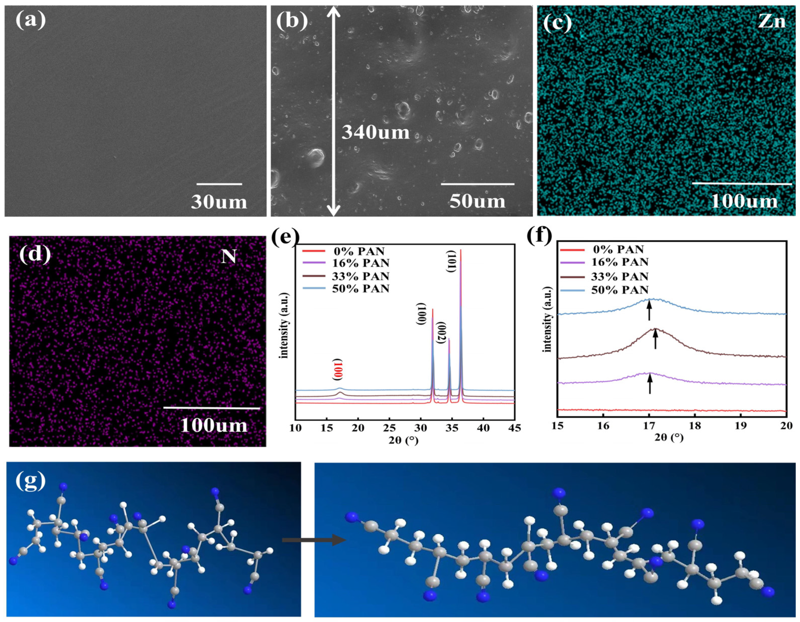
The SEM image in Figure 2a presents the surface morphology of the ZnO/PAN/Ecoflex composite membrane. It is evident that the surface of the composite membrane is very smooth, and ZnO and PAN powder are evenly distributed throughout the Ecoflex matrix, without powder agglomeration. Meanwhile, as illustrated in Figure 2b, the cross-sectional SEM image reveals the thickness of the membrane is 340 um, which is basically consistent with the results required by the preparation process, further indicating the accuracy of the fabrication process of the composite membrane. Moreover, under the further enlarged characterization of the composite membrane cross-section (Figure S2), we can clearly see the distribution of ZnO particles and PAN particles in the matrix, which further proves the uniformity of the distribution of ZnO particles and PAN particles. In addition, Figure 1c,d and Figure S3 in the supporting information show the EDS images of the four elements of Zn, N, O and Si in the composite membrane. Zn and N represent ZnO and PAN, respectively, and the EDS images of Zn and N in Figure 1c,d show that the ZnO and PAN particles are evenly distributed within the flexible substrate.
As illustrated in Figure 2e,f, the ZnO/PAN powder crystals were characterized by XRD analysis, and the interaction and working mechanism between ZnO and PAN were further discussed. It can be observed from the XRD pattern (Figure 1e) that there are three distinct diffraction peaks at 32.0°, 34.4°and 36.2°, which correspond to the hexagonal fibrillated structure crystal planes of ZnO at (100), (002) and (101), respectively [27]. At the same time, the primary characteristic peak of PAN, which corresponds to (100) crystal planes, is located at 17° [28] (the red mark). Furthermore, Figure 2f shows the magnified diffraction XRD pattern of the 17° peak with 2θ = 17° being the main diffraction peak of PAN. As the PAN mass grows, the 17° peak intensity of ZnO/PAN powder progressively rises and then falls. In addition, we also see a significant shift of the 17° peak of PAN. Two molecular conformations of PAN are the 31-helical conformation and the planar zigzag conformation [28,29]. The planar zigzag conformation has a larger dipole moment than the 31-helical conformation, while the piezoelectric properties are proportional to the dipole moment [24]. According to studies in the literature [30], the 17° peak of PAN will move to the left when the 31-helical conformation dominates. As the PAN mass fraction increases, the 17° peak shifts toward the right and subsequently toward the left, which proves that the 31-helical conformation of PAN can be transformed to the planar zigzag conformation by means of doping. At 33%, the ZnO/PAN/Ecoflex composite membrane has the largest planar zigzag content and should have the best piezoelectric properties. Figure 2g shows the PAN conformation transition.

3.2. Piezoelectric Performance of the HFPS

It is crucial to comprehend the workings of the HFPS before testing its electrical performance. Figure 3a shows the power generation mechanism of an HFPS in a complete working cycle. In simple terms, when an external force is applied, the HFPS deforms, and as a result, electrons flow in the external load circuit because the internal polarization strength varies and creates a potential difference between the upper and lower electrodes. When the external force ceases to act, the HFPS regains its original shape, generating a current that flows in the opposite direction.
To test and compare the electrical output properties of ZnO/PAN/Ecoflex composite membranes with different proportions, we placed different composite membranes under vertical compression and applied periodic force (20 N) by linear motor at a relative low frequency of 1.1 Hz and a load resistance of 600 MΩ (All tests in this paper were performed under these conditions without special explanation). In Figure 3b,c, the piezoelectric output exhibits a trend of rising and then decreasing with increasing PAN content (1 × 1 cm2 effective area). The maximum output voltage and current of the HFPS are 19.6 V and 52.7 nA, respectively, at a PAN ratio of 33%. This is line with the findings of the earlier XRD characterization analysis, which further verifies that ZnO can promote the transformation of the conformation of PAN from the 31-helical conformation to planar zigzag conformation and enhance the piezoelectric performance of PAN. Compared to the case without PAN addition, the output voltage of the device at this point increases by about 140% and the current by about 100%. There is a clear indication that the synergistic piezoelectric influence of the ZnO and PAN shows greater piezoelectric performance compared to a single material. The improvement in the piezoelectric characteristics of the HFPS is mostly attributable to the increase in the planar zigzag conformation content in the doped ZnO and PAN powders and the decrease in the agglomeration of the powders in the substrate when compared to the individual materials. Furthermore, in order to further analyze the piezoelectric properties of the thin HFPS, a d33 test was conducted, and the detection result of d 33 can be seen in Figure S4. The relative dielectric constant and dielectric loss of the composite films were also measured. As shown in Figure S5a, after the introduction of PAN, the value of relative permittivity increased from about 3.1 to 4. Moreover, as shown in Figure S5b, the dielectric loss value of the ZnO/PAN/Ecoflex composite membrane is slightly higher than that of the pure ZnO composite membrane, but it is very close to both around 0.01. This is due to the fact that the synergistic piezoelectric effect of ZnO and PAN leads to enhanced piezoelectric properties of the composite membrane, further demonstrating the accuracy of the test results. Furthermore, due to the completely symmetrical structure of the HFPS, when it is connected in the forward direction and reverse direction, it will present the same size and opposite direction of output electrical signals, indicating that it is a pure piezoelectric signal. As shown in Figure 3d,e, this traditional switch polarity test shows that the output voltage and current peak values of the HFPS are practically consistent in both forward and reverse modes.
In order to compare the performance status of sensors, a series of parameters are specified as a measure of sensor performance, generally including sensitivity, linearity, monitoring range, and durability. We have tested these performance parameters of the sensor. As we all know, sensitivity, linearity, and response range are very important for sensors. Typically, sensitivity is defined as the ratio of the output signal to the change in the applied stimulus. At the same time, linearity is another important desirable characteristic of a sensor. To facilitate data processing, sensors are expected to show a linear relationship between input and output. It is a non-linear calculation of the degree to which the sensor output deviates from the defined calibration curve. The value of the coefficient of determination ( R 2 ) is determined by linear regression, and if the R 2 value is large, the sensor performance is linear. At the same time, as one of the criteria for sensor performance evaluation, the sensing range can be defined as the maximum and minimum values of the parameters that can be measured through the sensor. In order to further characterize the response of the HFPS under different mechanical forces, the influence of dynamic external forces on its output signal is studied by applying variable periodic external forces on its surface. Figure 4a,c show the relationship between the measured output voltage/current of the HFPS and the force applied by the sensor. As the external force is increased from 100 to 900 kPa, the output voltage and current of the HFPS gradually increase, and the relationship is approximate with the increase of the external force. At this time, the piezoelectric output signal is strongly dependent on the applied deformation force. In general, due to the enhancement of external force, the deformation of piezoelectric devices becomes more and more serious, so the larger the piezoelectric potential generated by the HFPS, the higher the output voltage and current. Subsequently, it is obvious that the increase in output voltage and current from 800 to 900 kPa is minimal since the effective distortion of the piezoelectric membrane achieves its boundary. It can be simply found that the response of the piezoelectric output to pressure (100–800 kPa) increases linearly. Therefore, the HFPS shows a wide monitoring range of 100–800 kPa. As described in Figure 4b, the voltage-pressure relationship of the HFPS depicts good linear piezoelectricity, satisfying the linear relationship of y = 0.042 × x + 12.64. The slope of the fitted voltage-pressure curve shows a sensitivity of 42 mV/kPa and a voltage linearity of 0.98491. Similarly, Figure 4d reveals that the current sensitivity was 0.056 nA/kPa and the linearity was 0.99121. Therefore, according to the above experimental results, HFPSs have a good response to various external pressure stimuli, showing excellent sensitivity, high linearity and a wide measurement range.
Figure 4e displays the voltage output of the HFPS at the operating frequency of 0.6–2.6 Hz (includes the human motion frequency). The results show that the output voltage of the HFPS is almost independent of different frequency, indicating that the device operates reliably and achieves stable output in this range. Moreover, the equation can be calculated for HFPS output voltage in the theoretical analysis.
U = Q C = h F d 33 A ε 0 ε r ,
in which, Q represents the accumulation of polarized charge on the surface of the device, C represents the capacitance, h denotes the thickness of the piezoelectric device, A is the area of the piezoelectric device, d 33 denotes the coefficient of piezoelectric strain, F represents the mechanical force applied to the piezoelectric device, ε 0 denotes the vacuum dielectric constant of the piezoelectric material, and ε r denotes the relative dielectric constant of the piezoelectric material. This shows that the HFPS output voltage stability at different frequencies is consistent with the theoretical analysis. In addition, durability testing of flexible sensors is essential because multiple uses can lead to an unrecoverable deformation of the sensor and affect its subsequent use. The stability test of the HFPS under pressure loading is illustrated in Figure 4f, where the inset shows the amplified waveforms at the 50th and 15,000th cycles. After 16,000 cycles, there is no distinct decrease in HFPS performance; it shows excellent mechanical stability and durability. Based on this information, we can infer that the created HFPS is capable of reliably detecting finger motion information and converting it into real-time electrical signal output, and HFPSs have broad application prospects in human–machine interaction.

3.3. Human–Machine Interaction Application

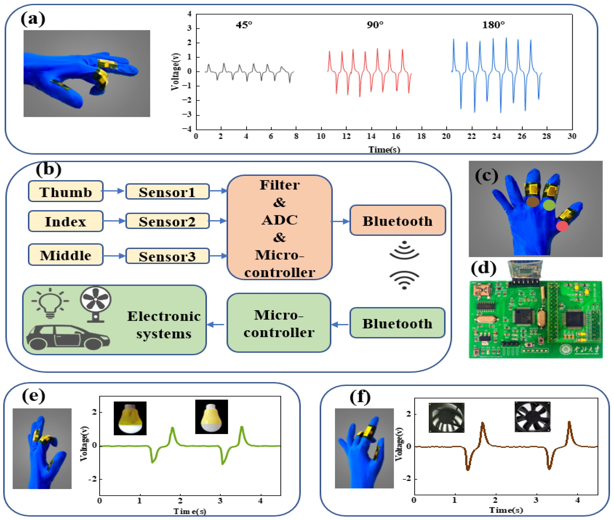
Owing to the fact that the HFPS has many advantages, such as excellent flexibility, unusual self-power ability, good flexibility, high linearity and reliable stability, it can be used as a wearable electronic device without power supply, meaning it can be successfully applied to HMI applications such as human posture monitoring and intelligent control. As shown in Figure 5a, the amplitude of the generated piezoelectric output differs for different finger bending angles. With the increase of finger bending degree, the deformation of the HFPS caused by it increases, so its output signal has also been significantly increased, and the single waveform of each curve can correspond to a complete motion cycle. When the finger bents at 45°, 90° and 180°, the output voltages are about 0.6 V, 1.2 V and 2 V. It can be seen that the piezoelectric output generated at different bending amplitudes of the finger is clearly differentiated. From the results, the HFPS can clearly display and judge different finger gesture signals, so it shows the possibility of intelligent control through finger gesture.
Figure 5b shows the operation principle of the intelligent glove in HMI, where the user wears the intelligent glove and makes different gestures, the gesture signal is recognized, and the operation of the corresponding electronic device is controlled via wireless transmission. The measurement of gestures is based on the piezoelectric output generated by the piezoelectric sensor on the smart glove when the finger changes from a straight state to a bent or tapped state. The finger bending or tapping causes the piezoelectric sensor to produce a pulse output. This signal is first filtered and transformed into a digital signal via an analogue-to-digital conversion (ADC) circuit, and then the microcontroller judges the sampled signal and sends the corresponding control signal via Bluetooth when it is greater than a threshold value. Electronic devices such as lights, fans and carts receive the control signals and perform the corresponding actions according to the signals. The circuitry of the data processing module, the ADC acquisition module and the Bluetooth module are shown in Figure 5d. Figure 5e demonstrates how the light can be switched on and off by bending the index finger: first, when the pulse signal is generated, the bulb lights up, and secondly, when the index finger is bent, the bulb turns off. With the intelligent glove we can also control the fan, as shown in Figure 5f by the signal from the bending of the middle finger to turn the fan on and off.
The intelligent glove recognizes the four gestures “forward”, “backward”, “left” and “right” (Figure 6). Different gestures have varying finger states, leading to different piezoelectric outputs from the three HFPSs. A threshold voltage of 0.5 V is set to determine whether the finger is bent or tapped. In simple terms, the direction of the carriage movement is determined by whether the knock signal is generated by the thumb, and the bending of the index and middle fingers determines straight ahead or steering. In the forward gesture, the index finger bends to produce a piezoelectric signal of about 1 V and the cart moves forward. In the backward gesture, the thumb first struck the side of the palm to generate a piezoelectric output of about 1.2 V, after which the index finger bend produced a voltage of about 1 V, commanding the carriage to move backward. The left turn and right turn gestures are similar to the above, with a bending movement from the index finger to the middle finger. The bend of the middle finger is a left gesture—the specialized circuit will collect more than 1 V in the channel where the middle finger is located and then make a judgment, and the car will turn to the left after receiving the control command. In the right gesture, the thumb first taps the palm side of the hand, followed by the bending of the middle finger. When the piezoelectric output generated by the combined motion of the two is recognized, the car turns right. A demonstration to control a wireless car by the intelligent glove is available in Video S1 of the supporting material.

4. Conclusions

In summary, we developed HFPSs through ZnO/PAN-based composite film and proposed a new type of intelligent glove. The HFPS has been produced by a simple mechanical mixing and coating process, which greatly improves the filling ratio of the piezoelectric material in the sensor. Owing to the synergistic piezoelectric effect of ZnO and PAN, the fabricated sensor achieved about the 140% and 100% increase in voltage and current, respectively. The voltage sensitivity and linearity of the HFPS under external pressure are 42 mV/KPa and 0.98. Furthermore, at 16,000 cycles of external pressure, the output voltage of the HFPS still has no obvious attenuation, reflecting its good stability and durability. We applied the HFPS to an intelligent glove due to its high-performance output, good sensitivity, stability and flexibility. In addition, we have built a human–machine interaction system of an intelligent glove, which accomplishes the on/off control of lights and fans and the two-dimensional movement of a cart through various hand gestures. The piezoelectric output generated by the finger movements acts as both a sensing signal and an energy supply, allowing the system to be used without power. Looking forward, the developed intelligent glove can be used to control more electronic devices, enabling deeper applications in the intelligent home and driving the further development of human–machine interaction.

Supplementary Materials

The following supporting information can be downloaded at: https://www.mdpi.com/article/10.3390/electronics12081782/s1, Figure S1: Test system; Figure S2: SEM image(cross-section); Figure S3: (a,b) EDS image; Figure S4: d 33 test of the ZnO/PAN/Ecoflex composite membrane; Figure S5: (a) Comparison of relative permittivity of composite films at different PAN ratios. (b) Comparison of dielectric loss of composite films at different PAN ratios. Video S1: Intelligent glove wireless control application. Reference [31] is cited in the Supplementary Materials.

Author Contributions

Conceptualization, M.W. and S.X.; methodology, M.W., J.Y. and S.Q.; validation, M.W., S.X. and J.Y.; investigation, M.W. and S.X.; writing—original draft preparation, M.W. and S.X.; writing—review and editing, J.H., X.H., J.Y. and X.C. All authors have read and agreed to the published version of the manuscript.

Funding

This work was supported by the National Natural Science Foundation of China (62171414, 52175554, 52205608, 62171415, 62101513), the Fundamental Research Program of Shanxi Province (20210302123059, 20210302124610, 20210302124170), China Postdoctoral Science Foundation (2022TQ0230, 2022M712324), Program for the Innovative Talents of Higher Education Institutions of Shanxi.

Data Availability Statement

Data included in the article and supplementary material.

Conflicts of Interest

The authors declare no conflict of interest.

References

  1. Cao, J.; Fu, X.P.; Zhu, H.; Qu, Z.Q.; Qi, Y.C.; Zhang, Z.; Zhang, Z.Q.; Cheng, G.G.; Zhang, C.; Ding, J.N. Self-Powered Non-Contact Motion Vector Sensor for Multifunctional Human-Machine Interface. Small Methods 2022, 6, 8. [Google Scholar] [CrossRef]
  2. He, Q.; Feng, Z.P.; Wang, X.; Wu, Y.F.; Yang, J. A Smart Pen Based on Triboelectric Effects for Handwriting Pattern Tracking and Biometric Identification. ACS Appl. Mater. Interfaces 2022, 14, 49295–49302. [Google Scholar] [CrossRef]
  3. Hu, Z.Y.; Wang, J.P.; Wang, Y.; Wang, C.; Wang, Y.W.; Zhang, Z.Y.; Xu, P.; Zhao, T.C.; Luan, Y.; Liu, C.; et al. A Robust and Wearable Triboelectric Tactile Patch as Intelligent Human-Machine Interface. Materials 2021, 14, 6366. [Google Scholar] [CrossRef] [PubMed]
  4. Shi, Q.F.; Zhang, Z.X.; Chen, T.; Lee, C.K. Minimalist and multi-functional human machine interface (HMI) using a flexible wearable triboelectric patch. Nano Energy 2019, 62, 355–366. [Google Scholar] [CrossRef]
  5. Pang, Y.K.; Chen, S.; Cao, Y.T.; Huang, Z.D.; Xu, X.C.; Fang, Y.H.; Cao, C.Y. Self-Powered Multifunctional Human-Machine Interfaces for Respiratory Monitoring and Smart System Control. Adv. Mater. Interfaces 2022, 9, 8. [Google Scholar] [CrossRef]
  6. Goh, Q.L.; Chee, P.; Lim, E.H.; Liew, G.G. Self-powered pressure sensor based on microfluidic triboelectric principle for human-machine interface applications. Smart Mater. Struct. 2021, 30, 8. [Google Scholar] [CrossRef]
  7. Doganay, D.; Cicek, M.O.; Durukan, M.B.; Altuntas, B.; Agbahca, E.; Coskun, S.; Unalan, H.E. Fabric based wearable triboelectric nanogenerators for human machine interface. Nano Energy 2021, 89, 12. [Google Scholar] [CrossRef]
  8. Yu, J.B.; Hou, X.J.; Cui, M.; Zhang, S.N.; He, J.; Geng, W.P.; Mu, J.L.; Chou, X.J. Highly skin-conformal wearable tactile sensor based on piezoelectric-enhanced triboelectric nanogenerator. Nano Energy 2019, 64, 14. [Google Scholar] [CrossRef]
  9. Wang, L.L.; Liu, W.Q.; Yan, Z.G.; Wang, F.J.; Wang, X. Stretchable and Shape-Adaptable Triboelectric Nanogenerator Based on Biocompatible Liquid Electrolyte for Biomechanical Energy Harvesting and Wearable Human-Machine Interaction. Adv. Funct. Mater. 2021, 31, 10. [Google Scholar] [CrossRef]
  10. Zhu, M.L.; Sun, Z.D.; Zhang, Z.X.; Shi, Q.F.; He, T.Y.Y.; Liu, H.C.; Chen, T.; Lee, C.K. Haptic-feedback smart glove as a creative human-machine interface (HMI) for virtual/augmented reality applications. Sci. Adv. 2020, 6, 14. [Google Scholar] [CrossRef]
  11. Shi, Q.F.; Lee, C.K. Self-Powered Bio-Inspired Spider-Net-Coding Interface Using Single-Electrode Triboelectric Nanogenerator. Adv. Sci. 2019, 6, 13. [Google Scholar] [CrossRef] [PubMed] [Green Version]
  12. Guo, H.; Wan, J.; Wu, H.X.; Wang, H.B.; Miao, L.M.; Song, Y.; Chen, H.T.; Han, M.D.; Zhang, H.X. Self-Powered Multifunctional Electronic Skin for a Smart Anti-Counterfeiting Signature System. ACS Appl. Mater. Interfaces 2020, 12, 22357–22364. [Google Scholar] [CrossRef]
  13. Wang, L.Y.; Liu, Y.M.; Liu, Q.; Zhu, Y.Y.; Wang, H.Y.; Xie, Z.Q.; Yu, X.G.; Zi, Y.L. A metal-electrode-free, fully integrated, soft triboelectric sensor array for self-powered tactile sensing. Microsyst. Nanoeng. 2020, 6, 9. [Google Scholar] [CrossRef]
  14. Zhou, X.R.; Parida, K.; Halevi, O.; Magdassi, S.; Lee, P.S. All 3D Printed Stretchable Piezoelectric Nanogenerator for Self-Powered Sensor Application. Sensors 2020, 20, 6748. [Google Scholar] [CrossRef]
  15. Zhao, C.L.; Jia, C.J.; Zhu, Y.S.; Zhao, T.M. An Effective Self-Powered Piezoelectric Sensor for Monitoring Basketball Skills. Sensors 2021, 21, 5144. [Google Scholar] [CrossRef]
  16. He, T.; Sun, Z.; Shi, Q.; Zhu, M.; Anaya, D.V.; Xu, M.; Chen, T.; Yuce, M.R.; Thean, A.V.-Y.; Lee, C. Self-powered glove-based intuitive interface for diversified control applications in real/cyber space. Nano Energy 2019, 58, 641–651. [Google Scholar] [CrossRef]
  17. Guo, H.; Pu, X.; Jie, C.; Yan, M.; Min-Hsin, Y.; Liu, G.; Tang, Q.; Chen, B.; Di, L.; Song, Q.J.S.R. A highly sensitive, self-powered triboelectric auditory sensor for social robotics and hearing aids. Sci. Robot. 2018, 3, eaat2516. [Google Scholar] [CrossRef] [Green Version]
  18. Deng, W.L.; Yang, T.; Jin, L.; Yan, C.; Huang, H.C.; Chu, X.; Wang, Z.X.; Xiong, D.; Tian, G.; Gao, Y.Y.; et al. Cowpea-structured PVDF/ZnO nanofibers based flexible self-powered piezoelectric bending motion sensor towards remote control of gestures. Nano Energy 2019, 55, 516–525. [Google Scholar] [CrossRef]
  19. Gao, C.; Long, Z.; Zhong, T.; Liang, S.; Xing, L. A self-powered intelligent glove for real-time human-machine gesture interaction based on piezoelectric effect of T-ZnO/PVDF film. J. Phys. D Appl. Phys. 2022, 55, 516–525. [Google Scholar] [CrossRef]
  20. Mu, J.; Xian, S.; Yu, J.; Li, Z.; Zhao, J.; Zhong, J.; Han, X.; Hou, X.; He, J.; Chou, X. Flexible and wearable BaTiO3/polyacrylonitrile-based piezoelectric sensor for human posture monitoring. Sci. China Technol. Sci. 2022, 65, 858–869. [Google Scholar] [CrossRef]
  21. Qi, Y.; Kim, J.; Nguyen, T.D.; Lisko, B.; Purohit, P.K.; McAlpine, M.C. Enhanced piezoelectricity and stretchability in energy harvesting devices fabricated from buckled PZT ribbons. Nano Lett. 2011, 11, 1331–1336. [Google Scholar] [CrossRef] [PubMed]
  22. Kumar, M.; Kumari, P.; Sahatiya, P. P(VDF-TrFE)/ZnO nanofiber composite based piezoelectric nanogenerator as self-powered sensor: Fabrication and characterization. J. Polym. Res. 2022, 29, 44. [Google Scholar] [CrossRef]
  23. Yu, J.; Xian, S.; Zhang, Z.; Hou, X.; He, J.; Mu, J.; Geng, W.; Qiao, X.; Zhang, L.; Chou, X. Synergistic piezoelectricity enhanced BaTiO3/polyacrylonitrile elastomer-based highly sensitive pressure sensor for intelligent sensing and posture recognition applications. Nano Res. 2022, 1–13. [Google Scholar] [CrossRef]
  24. Wang, W.; Zheng, Y.; Jin, X.; Sun, Y.; Lu, B.; Wang, H.; Fang, J.; Shao, H.; Lin, T. Unexpectedly high piezoelectricity of electrospun polyacrylonitrile nanofiber membranes. Nano Energy 2019, 56, 588–594. [Google Scholar] [CrossRef]
  25. Tian, G.; Deng, W.; Gao, Y.; Xiong, D.; Yan, C.; He, X.; Yang, T.; Jin, L.; Chu, X.; Zhang, H.; et al. Rich lamellar crystal baklava-structured PZT/PVDF piezoelectric sensor toward individual table tennis training. Nano Energy 2019, 59, 574–581. [Google Scholar] [CrossRef]
  26. Sun, Y.; Liu, Y.; Zheng, Y.; Li, Z.; Fan, J.; Wang, L.; Liu, X.; Liu, J.; Shou, W. Enhanced Energy Harvesting Ability of ZnO/PAN Hybrid Piezoelectric Nanogenerators. ACS Appl. Mater. Interfaces 2020, 12, 54936–54945. [Google Scholar] [CrossRef]
  27. Thakur, P.; Kool, A.; Hoque, N.A.; Bagchi, B.; Khatun, F.; Biswas, P.; Brahma, D.; Roy, S.; Banerjee, S.; Das, S. Superior performances of in situ synthesized ZnO/PVDF thin film based self-poled piezoelectric nanogenerator and self-charged photo-power bank with high durability. Nano Energy 2018, 44, 456–467. [Google Scholar] [CrossRef]
  28. Rizzo, P.; Auriemma, F.; Guerra, G.; Petraccone, V.; Corradini, P. Conformational Disorder in the Pseudohexagonal Form of Atactic Polyacrylonitrile. Macromolecules 1996, 29, 8852–8861. [Google Scholar] [CrossRef]
  29. Hobson, R.J.; Windle, A.H. Crystalline structure of atactic polyacrylonitrile. Macromolecules 1993, 26, 6903–6907. [Google Scholar] [CrossRef]
  30. Minagawa, M.; Taira, T.; Yabuta, Y.; Nozaki, K.; Yoshii, F. An Anomalous Tacticity−Crystallinity Relationship:  A WAXD Study of Stereoregular Isotactic (83−25) Poly(Acrylonitrile) Powder Prepared by Urea Clathrate Polymerization. Macromolecules 2001, 34, 3679–3683. [Google Scholar] [CrossRef]
  31. Bhunia, R.; Das, S.; Dalui, S.; Hussain, S.; Paul, R.; Bhar, R.; Pal, A.K. Flexible nano-ZnO/polyvinylidene difluoride piezoelectric composite films as energy harvester. Appl. Phys. A 2016, 122, 637. [Google Scholar] [CrossRef]
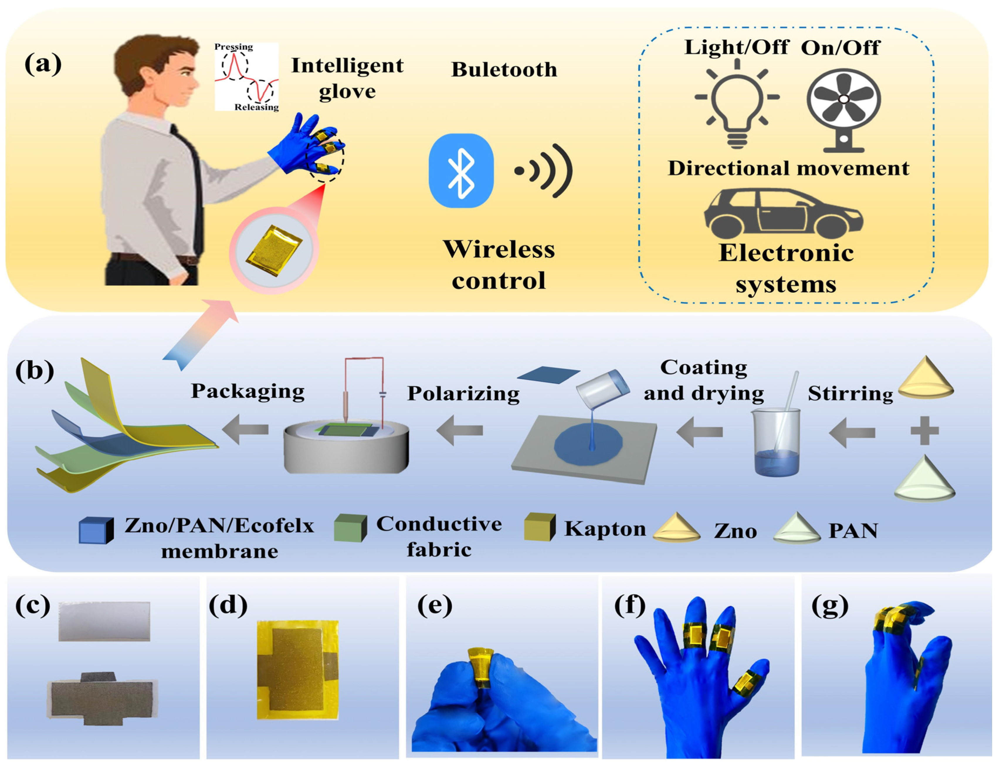
Figure 1. (a) The concept diagram of intelligent gloves for human–machine interaction applications; (b) The preparation process of the HFPS; (ce) Photograph of the HFPS; (f,g) Photograph of the intelligent glove.
Electronics 12 01782 g001
Figure 2. (a,b) SEM image (surface and cross-section); (c,d) EDS image; (e,f) XRD of ZnO /PAN powder; (g) Transformation of the 31-helical conformation of PAN to planar zigzag conformation.
Electronics 12 01782 g002
Figure 3. (a) The operating principle of the HFPS; (b,c) The output voltage/current of the HFPS with various PAN proportions; (d,e) Switching test (applied force: 20 N; load resistance: 600 MX).
Electronics 12 01782 g003
Figure 4. (a,c) The output voltage/current under various pressures; (b,d) The linear fitting analysis based on (a,c) calculations, respectively; (e) The frequency response of the HFPS; (f) stability test.
Electronics 12 01782 g004
Figure 5. (a) The output voltage at different bending angles of the HFPS being attached to the finger; (b) The working principle of intelligent gloves for human−machine interaction application; (c) Intelligent glove diagram; (d) Circuit board for intelligent gloves; (e) The intelligent glove controls the light bulb switch; (f) The intelligent glove controls the fan switch.
Electronics 12 01782 g005
Figure 6. Four different gestures to control the four directions of movement of the car.
Electronics 12 01782 g006
Disclaimer/Publisher’s Note: The statements, opinions and data contained in all publications are solely those of the individual author(s) and contributor(s) and not of MDPI and/or the editor(s). MDPI and/or the editor(s) disclaim responsibility for any injury to people or property resulting from any ideas, methods, instructions or products referred to in the content.