Abstract
This paper presents an experimental setup of magnetic field taper variations to optimize the efficiency of a Ka-band pulsed gyrotron. Experimental optimization of the gyrotron’s efficiency is presented. The efficiency dependence on three input parameters—beam current, magnetic field amplitude, and variations in the magnetic field taper profile—is studied. A gyrotron electron efficiency improvement from 25.4% for a non-tapered magnetic curve to 36.4% for a tapered magnetic curve is measured. The stability of the millimeter wave excitation in the cavity is also affected by the magnetic taper gradient. The magnetic taper is obtained by a practical modification of the solenoid that leads to an 11% electron efficiency improvement. Magnetic tapering can be combined with other types of efficiency enhancement concepts to obtain an overall improved efficiency that can be important for industrial applications.
1. Introduction
Gyrotrons [1] have been established as essential tools for generating high-power millimeter wave radiation, making significant contributions to a wide range of scientific and technological endeavors [2]. The gyrotron’s efficiency has been discussed in earlier works [3,4,5,6,7]. A theoretical examination of a magnetic linear taper for efficiency enhancement is described in ref. [4], but with a high electron pitch factor up to 2.5. A theoretical model predicted that magnetic field tapering with a positive gradient tends to increase the initial frequency mismatch, resulting in higher net energy transfer to the wave [5]. Ref. [6] describes an experimental study where a pitch factor of 1.8 and a linear magnetic taper were used, with up to 65% electron efficiency being reported. Ref. [8] describes a 60 GHz complex cavity gyrotron with a higher pitch factor of 2, where a magnetic taper effect is considered theoretically and experimentally. Efficiency improvement was seen in theory up to 12% taper, but in the experiment for the highest current of 8 A, the efficiency was improved up to 3% taper. Nevertheless, more recent works [9,10,11] have explained that such a high pitch factor, although capable of improving the electron efficiency according to [9]
where η is the electron efficiency (output power divided by the electron kinetic energy), is the perpendicular efficiency (output power divided by the electron tangential kinetic energy), and is the pitch factor (the tangential velocity divided by the axial velocity), may cause instability, cathode bombardment, secondary emission, parasitic oscillations, and velocity spread [9,10]. In modern gyrotrons, the pitch factor is typically between 1.2 and 1.5 [2].
Ref. [12] presents a theoretical investigation of a 500 GHz gyrotron with a pitch factor of 1.43. It was found that the linearly tapered magnetic field had a significant effect on the operating frequency, the frequency tuning bandwidth, and the interaction efficiency. Considering the electron spread, a 1% taper improved the efficiency from ~11.5% to 12%. A stronger taper led to a significant reduction of the efficiency.
Ref. [13] indicates the importance of analyzing a practical magnetic curve taper rather than a theoretical curve, which is typically difficult to realize in practice. A theoretical examination of a parabolic taper with a curve that resembles a small additional correction solenoid was conducted. The contribution to the efficiency in soft and hard self-excitation regions was analyzed and efficiency improvement was proven to be feasible.
Magnetic tapering was also considered for high-frequency second harmonic gyrotrons. A linear and parabolic magnetic profile were theoretically checked for 394 GHz gyrotron efficiency enhancement [14].
There are other methods for efficiency enhancement, such as depressed collectors [15,16]. An example is in ref. [17], where a theoretical design aimed for efficiency enhancement based on a hard excitation region and three-staged depressed collector, but without a tapered magnetic field. Such concepts may be combined with the linear magnetic taper. A prebunching section for increased electron efficiency in a 330 GHz gyrotron was also studied theoretically [18], and a lossy belt in the interaction circuit together with a down-tapered magnetic field were considered in a 1 THz gyrotron to double the electron efficiency to ~6% [19]. A summary of several theoretical works and a few experimental works regarding gyrotron efficiency improvements is presented by Nusinovich [20] (pp. 72–75).
Systematic experimental studies of gyrotron efficiency [21] are important to support theoretical works. Recently, in ref. [22], various magnetic field taper configurations were studied experimentally in a 30 GHz gyrotron. It was concluded that a ~3.5% magnetic taper improved the electron efficiency by a 1.3 factor (from 27% to 36%), but it was performed in the second harmonic. Still, experimental works with a practical magnetic field profile in the fundamental harmonic are needed.
In this work, an experimental study of gyrotron efficiency in the Ka-band (35 GHz) is presented. A unique implementation of the solenoid allows for the application of a fixed magnetic profile while varying the amplitude of the magnetic field. The magnetic profile is systematically changed among eight curves, and for each curve the magnetic field amplitude is increased gradually in search of the maximal efficiency. This concept differs from other works (such as ref. [22]) in that changing the magnetic curve also changes the magnitude of the magnetic field. Three-dimensional experimental electron efficiency mapping is performed as a function of the following input parameters: (a) beam current, (b) magnetic field amplitude, and (c) magnetic field profile. Many theoretical works use mathematical profiles (linear or parabolic), but these are complex to realize practically. In this work, a practical profile is chosen and checked experimentally. The optimal gyrotron electron efficiency improvement as a function of the input parameters is obtained. Moreover, the gyrotron is operating in the fundamental harmonic and in pulse mode.
2. Magnetic Field Profile
The gyrotron’s solenoid was simulated (in CST studio 2023) for eight different profiles of the magnetic field (Figure 1). The magnetic field was slightly modified starting from zero gradient (with 0.5% homogeneity, curve #0) up to a maximal gradient, considering a feasible magnetic field profile that can be obtained by slightly changing the solenoid through adding windings in a correction solenoid.
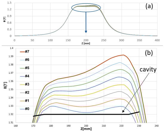
Figure 1.
Magnetic taper curves (a) and a zoom-in of the cavity region (b).
3. Experimental Setup
A copper pulsed solenoid was used, enabling modifications of the magnetic field profile according to the simulations in Figure 1. The solenoid comprised a main part and a correction part as seen in Figure 2. The correction part was connected in series to the main part and to the same current source. For curve #0, only the main solenoid was used. For the tapered curves, the correction solenoid was added and was modified (by adding windings) to obtain the various simulated profiles. As seen in Figure 2, the correction solenoid length is half that of the main solenoid. For curve #1, it had ~1/160 windings relative to the main solenoid. For each following curve, the same number of windings were added. The same current operated both parts in series. Separating the solenoid parts and operating them with separated sources might lead to undesired variations in the magnetic profile. A serial connection, and using a single current source, ensures the magnetic curve is anchored. For each profile, a set of experiments was conducted.
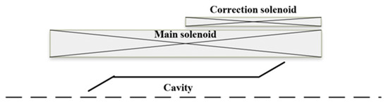
Figure 2.
The main part and correction part of the solenoid.
The gyrotron was operated with a pulsed ~1.3 T magnetic field (the solenoid pulse duration was ~40 ms [23]) radiating in the Ka-band. It should be noted that a used magnetron injection gun (MIG) in a triode configuration was taken from the gyrotron tube in ref. [24] and few adjustments were made. Therefore, the gun was not fully compatible with the tube and reduced the fundamental electron efficiency of the tube. The setup parameters are detailed in Table 1, and a picture of the gyrotron is seen in Figure 3.

Table 1.
The gyrotron parameters.
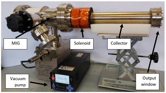
Figure 3.
Gyrotron Ka-band.
The diagnostic setup is presented in Figure 4. The output of the gyrotron was coupled into an external mode converter, delivering a TE10 rectangular mode in a standard WR28 waveguide. Then, a calibrated coupler (−10 dB), power attenuators (fixed: −20 dB × 2, tunable: −14.7 dB) and splitter, detector (QuinStar, Torrance, CA, USA, QEA-FBFBAP), and mixer (Marki, Morgan Hill, CA, USA, MM10832H) were connected. The power was measured in the calibrated detector channel. The mixer was fed with L.O. (Avantek, Santa Clara, CA, USA, YIG tuned oscillator Y089-4056) and tuned to 35.2 GHz. This channel was used to verify the proper frequency in each operation, rejecting any result with a frequency content indicating parasitic mode interference. Thus, only measurements with the single desired mode of forward interaction in the cavity were considered.
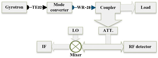
Figure 4.
Schematic of the diagnostic setup.
4. Experimental Results
A typical output measurement of a single-mode operation is presented in Figure 5a. The electron beam current (green) and the detector voltage (yellow) were measured with an oscilloscope (Keysight, Colorado Springs, CO, USA, DSOX1204A). A beam current of ~2.3 A can be seen during the ~20 µs pulse. The solenoid current that had a pulse with a much longer duration (~40 ms) was stable during the 20 µs operation. Magnetic taper curve #4 was used in this measurement. According to the careful calibration, the measured ~112 mV represents ~35 kW in this pulse. The IF signal was measured by a 4 GHz bandwidth oscilloscope (Tektronix, Bracknell, UK, TDS7404B). Figure 5b presents the IF measurement through the mixer channel with L.O. of 35.2 GHz (upper green curve). An FFT of the signal is also presented in the lower orange curve, where a clear peak can be seen. A zoom-in into one period of the IF is presented in Figure 5c, where a 4.48 ns period was measured. This period represents the 223 MHz IF signal and corresponds to the ~35 GHz radiation frequency emitted by the gyrotron. In this measurement, a clear single mode can be seen both in the FFT measurement and in the zoom-in of the IF signal where a pure sine wave was measured. The obtained frequency fits the design of the gyrotron for the TE02 mode. To experimentally find the optimal efficiency, the operational parameters were modified. Similar measurements were performed while slightly varying the solenoid current and the electron beam current for each configuration of the solenoid magnetic profile. Many measurements were taken and the data were collected. For each operation, the electron efficiency was evaluated as the output radiated power divided by the input electron gun power.
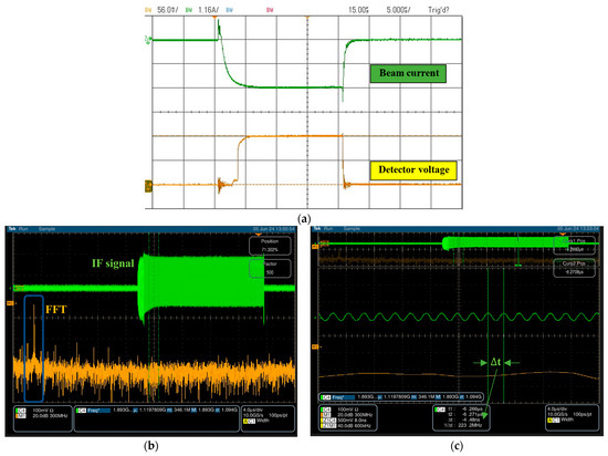
Figure 5.
Measured signal and spectral content of a pulse with a single mode. (a) Typical ~20 µs pulse beam current (green, 1.16 A/div) and detector voltage (yellow, 56 mV/div). (b) IF signal from the mixer (green, 100 mV/div) and spectral content FFT (orange, 300 MHz/div) of the IF signal with single-mode TE02 (~223 MHz), clear peak is seen, marked in a blue box. (c) Zoom to one period of the IF signal, showing a single mode with a ~4.48 ns period pointed with the green arrow (IF: ~223 MHz).
The frequency readings were not conclusive when varying the parameters (magnetic curve, cathode current, and magnetic field) in some working points. These measurements were excluded from the collected data. In order to understand the nature of theses readings, the setup was slightly modified by removing the mode converter, and the measurements were done through free space coupling. The power calibration was lost, but modes other than TE02 were measurable as well. It was found that another mode was excited, and, as a result, two modes were measured simultaneously.
An example of two-mode excitation measurement is seen in Figure 6. This measurement was performed with magnetic curve #4, with a solenoid current of ~750 A and a beam current of ~2.3 A. The detector voltage shows a clear signal (Figure 6a), but as can be seen in the FFT of the IF signal (Figure 6b), two modes are excited. There are two peaks that represent the two operating modes. A zoom-in into the IF is presented in Figure 6c, where two periods are clearly seen. The longer one was measured to be 4.91 ns. This period represents the 203 MHz IF signal and corresponds to ~35 GHz; this is the TE02 mode (similar to Figure 5). In Figure 6d, there is a further zoom-in into the shorter period that is seen in the IF. A 608 ps period was measured, representing the IF frequency of 1.64 GHz; this is the 35.2 − 1.64 = 33.5 GHz gyrotron frequency. This frequency corresponds to mode TE22, which is the closest mode to the designed mode TE02. Such measurements, with two excited modes, were excluded from the 3D results (Figure 7 and Figure 8).
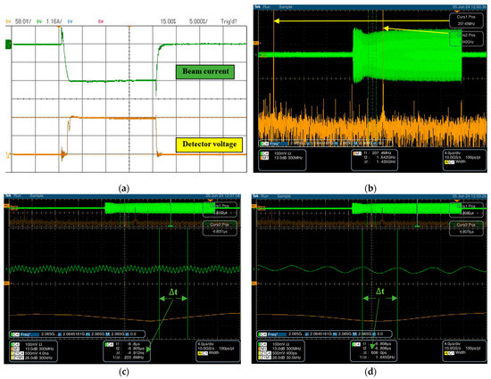
Figure 6.
Measured signal and spectral content of a pulse with two modes. (a) Typical ~20 µs pulse beam current (green, 1.16 A/div) and detector voltage (yellow, 58 mV/div). (b) IF signal from the mixer (green, 100 mV/div) and spectral content FFT (orange, 300 MHz/div) of the IF signal with two modes: TE02 (~203 MHz) and TE22 (~1.64 GHz). (c) Zoom to TE02 signal period marked in green arrow of 4.91 ns (IF: ~203 MHz). (d) Zoom to TE22 signal period marked in green arrow of 608 ps (IF: ~1.64 GHz).
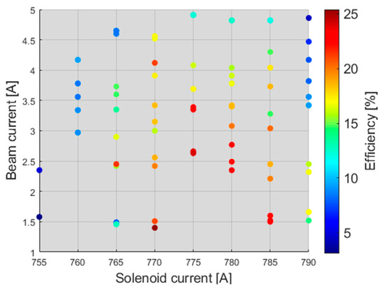
Figure 7.
Electron efficiency vs. beam and solenoid currents for curve #0.
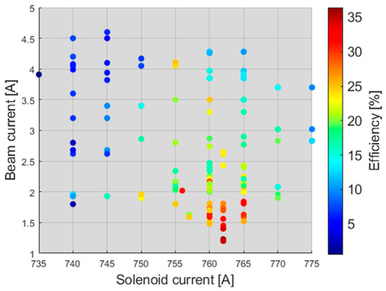
Figure 8.
Electron efficiency vs. beam and solenoid currents for curve #4.
The results were analyzed to find the most efficient working point as a combination of the magnetic field and beam current for all magnetic curves. The results for each magnetic curve are summarized in a 3D graph (using MatLab 2023). An example for curve number #0, i.e., zero magnetic gradient, is shown in Figure 7. The optimal working point was found at a beam current of 1.4 A and a solenoid current of 770 A. More measurements were taken with the solenoid current between 775 A and 780 A in this magnetic curve, but the results were unstable in this regime and therefore are not seen in the graph. The IF measurements showed that more frequencies were excited in relation to the parasitic modes together with the main mode frequency. Therefore, these unstable results are not presented.
Similar graphs were made for all the curves. The most efficient working points were taken out from each graph and are summarized in Figure 9. As can be seen, the highest efficiency was measured in curve #4 as 36.4%. This is related to the 25.4% efficiency measured at the fundamental curve #0 representing zero gradient. Figure 9b presents the beam current and the solenoid current at the optimal points of each curve.
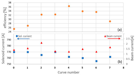
Figure 9.
Most efficient working points: (a) the electron efficiency for the curves and (b) solenoid current and beam current at the optimal efficiency working points.
5. Discussion
The gyrotron electron efficiency for a set of magnetic curves with various practical tapers was measured. For every curve, the setup enabled varying the magnetic field magnitude while keeping the magnetic profile unchanged. Two parameters were experimentally swept for each curve: the beam current and the magnetic field magnitude. The efficiency was evaluated and thus an optimal working point was obtained for every curve.
The basic efficiency for curve #0 was 25.4%. An optimal efficiency improvement of 11% (from 25.4% to 36.4%) was obtained for curve #4 with the magnetic taper. The stability of the results was also affected by the gradient. While in curve #0 the higher efficiency working-point regime was not stable (Figure 7), in curve #4 the working-point regime of the higher efficiency was much more stable (Figure 8). A possible explanation is the parasitic mode TE22 (33.5 GHz) excitation. The tapered magnetic field enhances the chosen mode and therefore suppresses the parasitic mode [25]. In the case of curve #4 (tapered profile), it was easier for a single mode to be excited than in the non-tapered case. As a result, the minimal starting current for single mode stable operation was reduced from 1.4 A to 1.23 A.
The magnetic taper used is not a theoretical linear curve but a practical curve that is obtained by a simple single correction solenoid based on the same current source of the main solenoid. Therefore, an 11% efficiency improvement is gained with the minimal additional complexity of the setup. Moreover, it can be added to other known efficiency improvement methods such as depressed collectors.
As a future work, it will be interesting to theoretically check the results of this experiment and explore more practical magnetic curves that may lead to even better results. A negative magnetic taper was also considered for efficiency enhancement [19,25,26]. The presented setup with modification of the solenoid structure can support such a future experiment and comparison to the positive taper investigated here.
Author Contributions
Conceptualization, M.P. and M.E.; Methodology, M.P. and M.E.; Software, S.S. and Y.S.; Validation, S.S. and M.P.; Formal analysis, Y.S., M.P. and M.E.; Investigation, S.S., Y.S. and M.E.; Resources, M.E.; Data curation, M.P.; Writing—original draft, S.S.; Writing—review & editing, M.E.; Visualization, Y.S.; Supervision, M.P. and M.E. All authors have read and agreed to the published version of the manuscript.
Funding
This research received no external funding.
Data Availability Statement
All the relevant data is in the manuscript.
Conflicts of Interest
The authors declare no conflicts of interest.
References
- Nusinovich, G.S.; Thumm, M.K.A.; Petelin, M.I. The Gyrotron at 50: Historical Overview. J. Infrared Millim. Terahertz Waves 2014, 35, 325–381. [Google Scholar] [CrossRef]
- Idehara, T.; Sabchevski, S.P.; Glyavin, M.; Mitsudo, S. The Gyrotrons as Promising Radiation Sources for THz Sensing and Imaging. Appl. Sci. 2020, 10, 980. [Google Scholar] [CrossRef]
- Flyagin, V.; Gaponov, A.; Petelin, I.; Yulpatov, V. The Gyrotron. IEEE Trans. Microw. Theory Tech. 1977, 25, 514–521. [Google Scholar] [CrossRef]
- Chu, K.R.; Read, M.; Ganguly, A. Methods of Efficiency Enhancement and Scaling for the Gyrotron Oscillator. IEEE Trans. Microw. Theory Tech. 1980, 28, 318–325. [Google Scholar] [CrossRef][Green Version]
- Lin, A.T. Mechanisms of efficiency enhancement in gyrotron backward-wave oscillators with tapered magnetic fields. Phys. Rev. A 1992, 46, R4516–R4519. [Google Scholar] [CrossRef] [PubMed]
- Read, M.; Chu, K.R.; Dudas, A. Experimental Examination of the Enhancement of Gyrotron Efficiencies by Use of Profiled Magnetic Fields. IEEE Trans. Microw. Theory Tech. 1982, 30, 42–46. [Google Scholar] [CrossRef]
- Gantenbein, G.; Borie, E. Gyrotron with a tapered external magnetic field. Int. J. Infrared Millim. Waves 1990, 11, 837–850. [Google Scholar] [CrossRef]
- Jory, H.; Bier, R.; Evans, S.; Felch, K.; Fox, L.; Huey, H.; Shively, J.; Spang, S. First 200 kW CW operation of a 60 GHz gyrotron. In Proceedings of the 1983 International Electron Devices Meeting, Washington, DC, USA, 16–24 August 1983; pp. 267–270. [Google Scholar] [CrossRef]
- Manuilov, V.N.; Polushkina, S.A. Behavior of helical electron beams in gyrotrons with high pitch factors. Radiophys. Quantum Electron. 2009, 52, 714–721. [Google Scholar] [CrossRef]
- Manuilov, V.N. Numerical simulation of low-frequency oscillations of the space charge and potential in the electron-optical system of a gyrotron. Radiophys. Quantum Electron. 2006, 49, 786–792. [Google Scholar] [CrossRef]
- Lu, D.; Fu, W.; Fedotov, A.; Glyavin, M.; Proyavin, M.; Yan, Y. Ultimate transverse power of pulsed low-voltage gyrotron beam. Phys. Plasmas 2022, 29, 093107. [Google Scholar] [CrossRef]
- Song, T.; Wang, W.; Zhang, C.; Huang, J.; Wang, S.; Chen, Q.; Liu, D.; Liu, S. Effects of the Magnetic Field Taper on a Continuously Frequency-Tunable Gyrotron. IEEE Trans. Electron Devices 2020, 67, 3815–3820. [Google Scholar] [CrossRef]
- Dumbrajs, O.; Nusinovich, G.S. Efficiency of gyrotrons with a tapered magnetic field in the regime of soft self-excitation. Phys. Plasmas 2018, 25, 013121. [Google Scholar] [CrossRef]
- Wang, X.; Xue, Q.; Zhang, S.; Liu, G.; Zhao, G.; Zhao, D. Effects of Different Magnetic Field Profiles on Output Power and Efficiency of a Second-Harmonic Gyrotron. IEEE Trans. Plasma Sci. 2019, 47, 5159–5164. [Google Scholar] [CrossRef]
- Morozkin, M.V.; Glyavin, M.Y.; Denisov, G.G.; Luchinin, A.G. A High-Efficiency Second-Harmonic Gyrotron with a Depressed Collector. Int. J. Infrared Millim. Waves 2008, 29, 1004–1010. [Google Scholar] [CrossRef]
- Bykov, Y.V.; Denisov, G.G.; Eremeev, A.G.; Flat, F.A.; Glyavin, M.Y.; Gorbachev, A.M.; Kalynova, G.I.; Kholoptsev, V.V.; Kopelovich, E.A.; Luchinin, A.G.; et al. Efficiency enhancement of gyrotron based setups for materials processing. In Proceedings of the 2009 34th International Conference on Infrared, Millimeter, and Terahertz Waves, Busan, Republic of Korea, 21–25 September 2009; pp. 1–2. [Google Scholar] [CrossRef]
- Nayek, N.; Joshi, M.K.; Sonkar, R.K.; Tiwari, T.; Bhattacharjee, R. Design and Efficiency Enhancement of a Ka-Band Industrial Gyrotron. IEEE Trans. Plasma Sci. 2020, 48, 3807–3814. [Google Scholar] [CrossRef]
- Gao, Z.-C.; Du, C.-H.; Li, F.-H.; Zhang, Z.-W.; Li, S.-Q.; Qi, X.-B.; Liu, P.-K. Design of a 330-GHz Frequency-Tunable Gyrotron With a Prebunched Circuit. IEEE Trans. Electron Devices 2022, 69, 2058–2065. [Google Scholar] [CrossRef]
- Gao, Z.C.; Du, C.H.; Li, F.H.; Zhang, Z.W.; Li, S.Q.; Liu, P.K. Forward-wave enhanced radiation in the terahertz electron cyclotron maser. Chin. Phys. B 2022, 31, 128401. [Google Scholar] [CrossRef]
- Nusinovich, G. Introduction to the Physics of Gyrotrons; Johns Hopkins University Press: Baltimore, MD, USA, 2004. [Google Scholar]
- Pagonakis, I.G.; Avramidis, K.A.; Gantenbein, G.; Rzesnicki, T.; Samartsev, A.; Jelonnek, J. Magnetic field profile analysis for gyrotron experimental investigation. Phys. Plasmas 2017, 24, 033102. [Google Scholar] [CrossRef]
- Proyavin, M.D.; Morozkin, M.V.; Luchinin, A.G.; Glyavin, M.Y.; Denisov, G.G. An Experimental Study of the Influence of the Longitudinal Magnetic-Field Distribution Profile on the Output Characteristics of a Gyrotron. Instrum. Exp. Tech. 2021, 64, 97–101. [Google Scholar] [CrossRef]
- Witman, M.; Avraham, E.; Ben-Moshe, R.; Pilossof, M.; Einat, M. Long-Pulse Uncooled Copper Magnet for Gyrotron. IEEE Trans. Electron Devices 2019, 66, 4928–4931. [Google Scholar] [CrossRef]
- Witman, M.; Einat, M.; Averbukh, M. Pulsed regulated high current source for solenoid. In Proceedings of the Electricity 2017, the Annual Convention of the Society of Electrical and Electronics Engineers in Israel (SEEEI), Eilat, Israel, 8–10 November 2017. [Google Scholar]
- Gao, Z.-C.; Du, C.-H.; Li, F.-H.; Liu, P.-K. Terahertz gyrotrons with inhomogeneous magnetic fields to suppress mode competition and enhance efficiency. J. Appl. Phys. 2021, 129, 043306. [Google Scholar] [CrossRef]
- Nusinovich, G.S. Cyclotron resonance masers with inhomogeneous external magnetic fields. Phys. Fluids B Plasma Phys. 1992, 4, 1989–1997. [Google Scholar] [CrossRef]


Disclaimer/Publisher’s Note: The statements, opinions and data contained in all publications are solely those of the individual author(s) and contributor(s) and not of MDPI and/or the editor(s). MDPI and/or the editor(s) disclaim responsibility for any injury to people or property resulting from any ideas, methods, instructions or products referred to in the content. |
© 2024 by the authors. Licensee MDPI, Basel, Switzerland. This article is an open access article distributed under the terms and conditions of the Creative Commons Attribution (CC BY) license (https://creativecommons.org/licenses/by/4.0/).