Article

A Data-Driven Control for Modular Multilevel Converters Based on Model-Free Adaptive Control with an Event-Triggered Scheme

1
School of Electrical Engineering, Shandong University, Jinan 250061, China
2
State Grid Shandong Electric Power Research Institute, Jinan 250000, China
*
Author to whom correspondence should be addressed.
Electronics 2024, 13(15), 2899; https://doi.org/10.3390/electronics13152899
Submission received: 12 June 2024 / Revised: 17 July 2024 / Accepted: 20 July 2024 / Published: 23 July 2024
(This article belongs to the Special Issue Development of Power Electronics and Smart-Grids)

Abstract

:
Modular multilevel converters (MMCs) have gained widespread adoption in high-voltage direct current (HVDC) transmission due to their high voltage levels, low harmonic content, and high scalability. However, conventional control methods such as finite control set model predictive control (FCS-MPC) suffer from a heavy computational burden and sensitivity to system parameter variations, limiting the performance of MMCs. This paper proposes a data-driven approach based on model-free adaptive control with an event-triggered mechanism that demonstrates superior robustness against parameter mismatches and enhanced dynamic performance in response to sudden output changes. Moreover, the introduction of the event-triggered mechanism effectively reduces redundant operations, decreasing the computational burden and switching losses. Finally, the proposed strategy is validated through a MATLAB/Simulink simulation model.

1. Introduction

Modular multilevel converters, with their modular cascaded structure, offer numerous benefits including high voltage levels, expandability, low harmonic content, and improved reliability, making them promising candidates for high-voltage and high-power applications in modern power systems [1,2]. However, unlike traditional two-level voltage source converters, MMCs necessitate simultaneous control of multiple objectives, including AC side currents, sub-module capacitor voltages, and circulating currents, leading to greater complexity in control algorithms [3].
Conventional linear controllers like PI and PR have been employed for multi-objective control of MMCs and are often implemented in cascaded or parallel structures. However, the design process for these control systems faces challenges, particularly in parameter tuning. Suboptimal parameter choices can significantly impact the control performance [4]. In recent years, model predictive control (MPC) has garnered considerable attention for MMC control strategies owing to the intuitive structure, excellent dynamic performance, and ability to accommodate multivariable constraints [5,6].
However, the implementation of FCS-MPC in converter control faces two major challenges. Firstly, the traditional model predictive control method relies on online prediction and rolling optimization, requiring the construction of a weighted cost function and exhaustive evaluation of all switching states or voltage levels. Consequently, as the number of sub-modules increases, the computational load grows geometrically [7,8]. Secondly, both conventional linear control and model predictive control necessitate accurate parameters for the circuit model [9]. Inaccuracies in the system model can lead to errors in the generated reference voltages, resulting in degraded power quality and even compromising system stability in severe cases [10]. Therefore, realizing robust predictive control with a manageable computational burden presents a significant challenge.
Numerous approaches have been investigated to address the computational load associated with FCS-MPC. A novel approach combines capacitor voltage sorting with MPC, transforming the problem from optimal state prediction to optimal level prediction control [11]. This technique effectively reduces the computational burden from  C 2 n n  to  N + 1  or  2 N + 1 . A fast MPC method is introduced in [12], where rolling optimization is performed only between the optimal output phase voltage of the previous instant and its neighboring voltage levels, limiting the search to 2–3 iterations per control cycle. A simplified two-stage MPC approach is proposed in [13]; it synergistically combines rolling optimization with search space optimization to minimize the prediction load for each control option. An event-triggered MPC algorithm tailored for power converters is presented in [14], where control signals are updated only when triggered, otherwise remaining constant. However, a common limitation of these approaches is the lack of consideration for the impact of model parameter mismatches.
To enhance the robustness, researchers have proposed various improved model predictive control methods, such as online parameter identification techniques. A least squares method combined with model predictive direct power control has been presented to improve the rectifier control performance, achieving online model parameter identification [15]. Nonetheless, this approach suffers from complex computations and poor dynamic performance in parameter identification. Subsequently, a new approach for online parameter estimation in model reference adaptive systems has been proposed, exhibiting good dynamic and steady-state performance. However, it requires initial inductance and resistance information [16]. In addition, researchers have proposed a class of control strategies that enhance robustness by incorporating the Lyapunov method. A robust nonlinear controller based on backstepping and the Lyapunov approach is presented in [17]; it can offer flexible power control for an MMC-HVDC system. A model reference adaptive method based on the Lyapunov function has been proposed to estimate line inductance online [18], effectively improving system robustness. Nevertheless, a limitation of the method is the inability to accurately estimate multiple circuit parameters simultaneously. Consequently, some studies have proposed multi-parameter online identification methods, but these methods are computationally intensive, consuming significant controller resources [19,20].
Additionally, researchers have developed model-free control technique to address this issue. This approach does not require a detailed mathematical model or detailed parameter values, thereby reducing the dependency of FCS-MPC on unknown model parameters. An ultra-local model of the system is established, and differential algebra is employed for model estimation [21,22]. The disturbance part in the ultra-local model can be observed using an observer for better compensation. There are numerous types of observers employed for converter applications, including Luenberger observers [23], sliding mode observers [24,25], high-gain observers [26,27], and extended state observers [27,28]. However, the gain in the ultra-local model is not identified or estimated but is obtained in advance through trial and error or experience, which restricts the model’s practical feasibility.
In the past few years, data-driven MMC controls have garnered significant attention. A control strategy combining a predictive neural network (PNN) with the FCS-MPC was proposed in [29] and achieved smooth and rapid identification of system dynamics, thereby successfully mitigating performance degradation due to parameter changes and model inaccuracies. Subsequently, a dynamic surface predictive control framework based on neural predictive factors is introduced in [30], combining the advantages of adaptive dynamic surface control and FCS-MPC. A scheme that integrates actor–critic learning algorithms with predictive current control based on neural predictors is studied in [31]. This approach improves and extends the standard FCS-MPC method, alleviating the system’s inherent uncertainties and unknown disturbances. A novel neural-network-based capacitor voltage balancing control scheme is established in [32]; it achieves more precise and faster voltage balancing control and provides insights for future intelligent control of capacitor voltage balancing. In [33], a robust MPC framework based on fuzzy logic is considered; it deploys a fuzzy approximation perspective with the potential to approximate unknown nonlinear functions accurately. This perspective allows for the explicit consideration of system nonlinear dynamics and uncertainties. A data-driven approach based on iterative learning predictive control for power converters is presented in [34]; it leverages iterative dynamic linearization techniques to effectively redesign the nonlinear system during each working cycle. This approach mitigates the impact of parameter disturbances while reducing tracking errors. In [35], model-free adaptive control is integrated into the FCS-MPC framework, replacing the original prediction component of MPC while retaining its value function and performing rolling optimization. However, this method still presents a computational challenge for the system.
To tackle the problem of a high computational burden and limited robustness in multi-objective control of MMC, this paper introduces a model-free adaptive control with an event-triggered mechanism (ET-MFAC) strategy for MMC. The advantages of this approach are as follows:
  • Simple control structure: This method combines an event-triggered mechanism with model-free adaptive control, eliminating the reliance on a system’s mathematical model and complex observer construction processes. This simplifies control algorithm design and reduces the computational burden.
  • High computational efficiency: This method avoids the complex process of rolling optimization of the cost function. Furthermore, the event-triggered mechanism only updates the control signal when the event-triggered error exceeds a certain threshold. Compared to FCS-MPC, the proposed method reduces program execution time by 20%, efficiently enhancing computational efficiency.
  • Robust performance: Due to its independence from precise mathematical models, this method achieves the control objective based solely on system input and output data, making it robust against model uncertainties and external disturbances.
This paper is organized according to the following structure: Section 2 derives the discrete-time mathematical model of MMC. Section 3 presents the event-triggered model-free adaptive control scheme for MMC. Section 4 provides simulation results based on MATLAB/Simulink and presents a comparative analysis with two other control approaches. Finally, Section 5 summarizes the key points of this paper.

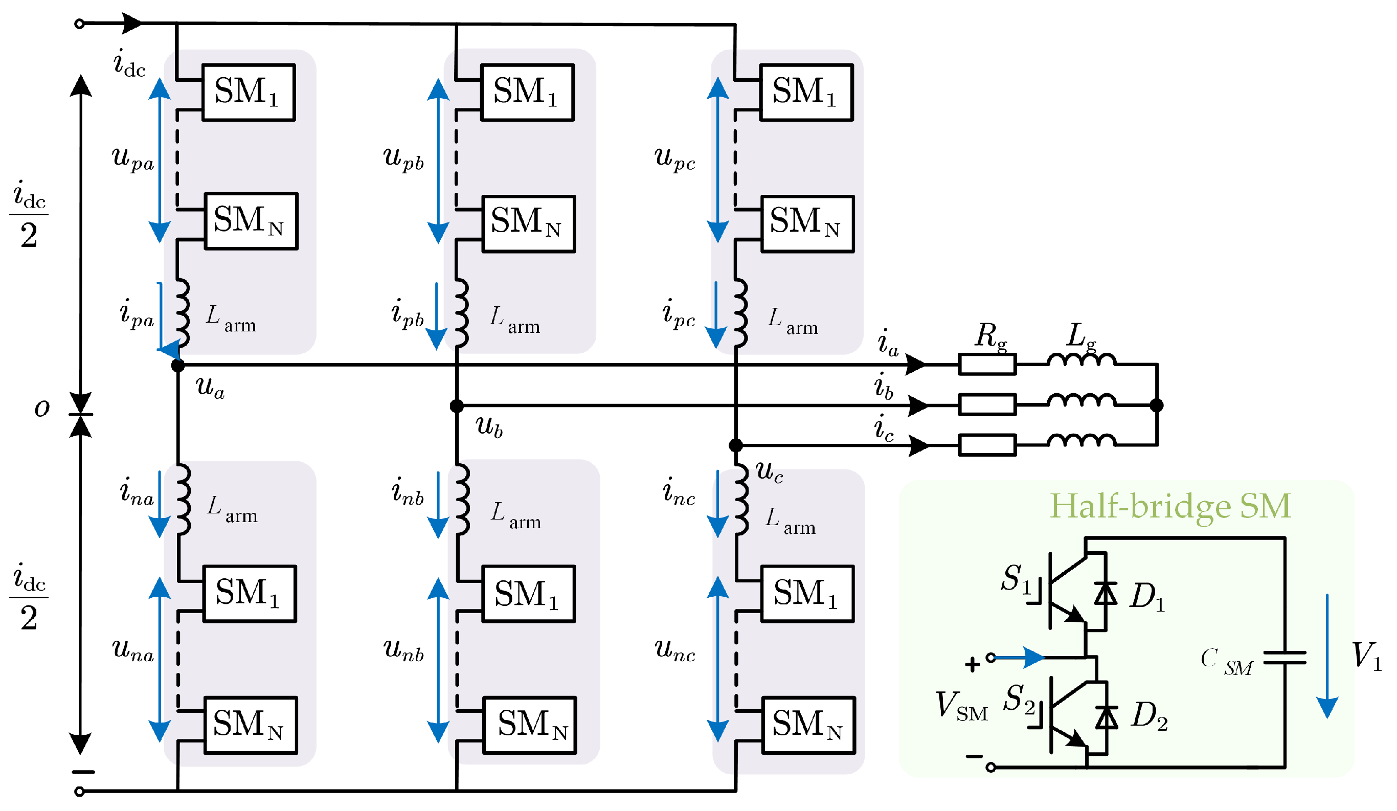
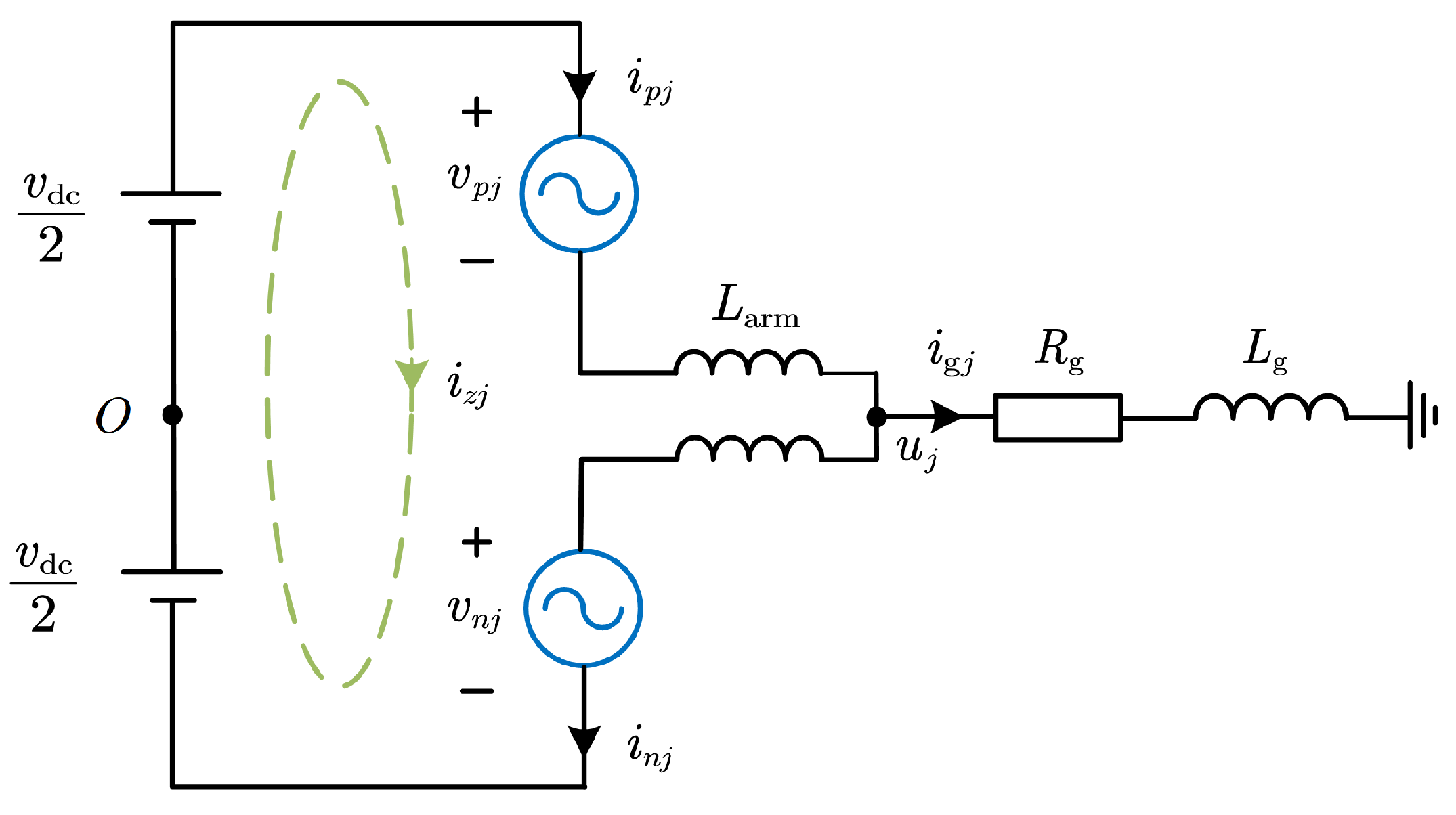
2. System and Modeling

Figure 1 depicts a typical three-phase MMC topology based on half-bridge sub-modules (SMs). Each phase comprises two arms: an upper arm and a lower arm. Each arm comprises N cascaded half-bridge SMs and an arm inductance L. A half-bridge SM includes two switching devices and a DC capacitor connected in parallel. Each SM can operate in two states: on or off. In the figure,  v p j  and  v n j j = a , b , c  represent the equivalent output voltages of the upper and lower arms, respectively, while  i p j  and  i n j  denote the currents flowing through the upper and lower arms, respectively. The term  i j  denotes AC side output current,  u j  represents AC side output voltage,  v dc  denotes DC side voltage,  L arm  represents arm inductance, and  R g  and  L g  denote AC side resistance and inductance, respectively.
Since the structure of each phase unit is identical, the ensuing discussion will focus on a single phase unit of the MMC to simplify the modeling process. Figure 2 shows the single-phase equivalent circuit of the MMC.
Based on Kirchhoff’s voltage law (KVL), the equations for the upper and lower arm circuits can be written as:
v dc 2 v p j L arm d i p j d t = R g i j + L g d i j d t
v dc 2 v n j L arm d i n j d t = R g i j L g d i j d t
The circulating current  i z j  and the corresponding voltage  v z j  across the arm inductance are given by:
i z j = i p j + i n j 2 = 1 3 I dc + i cir j
where the DC component  I dc  is responsible for the energy exchange between SMs and the external system, and it is directly related to the active power. The AC even-order harmonic component  i cir j  of the circulating current, dominated by the second harmonic, results in additional losses.
According to Equations (1) to (3), the key dynamic expressions of the output current and the internal arm current are presented below:
d i g j d t = R g L eq i g j + 1 2 L eq v n j v p j
L arm d i z j d t = v dc 2 v n j + v p j 2 = v z j
where  v z j  represents the voltage across the arm inductance due to the circulating current, and  L eq = L g + 0.5 L arm . Forward Euler discretization of Equations (4) and (5) yields:
i g j k + 1 = 1 R g L eq T s i g j k + T s 2 L eq v n j k v p j k
i z j k + 1 = T s L arm v z j k + i z j k
where  T s  represents the control period, and k denotes the sampling time sequence.
The mathematical model indicates the following conclusions:
(1) The magnitude of  i g j  is related to the differential-mode voltage ( v diff j = v n j v p j ) between the upper and lower arms.
(2) The magnitude of  i z j  flowing through the arms is related to the common mode voltage of the upper and lower arms ( v com j = v n j + v p j ).
(3) The circulating current flowing through the inductances  L arm  of the upper and lower arms generates voltage  v z j .
(4) System parameters such as the arm inductance and filter impedance ( R arm , R g and L g ) have a significant effect on the mathematical model.

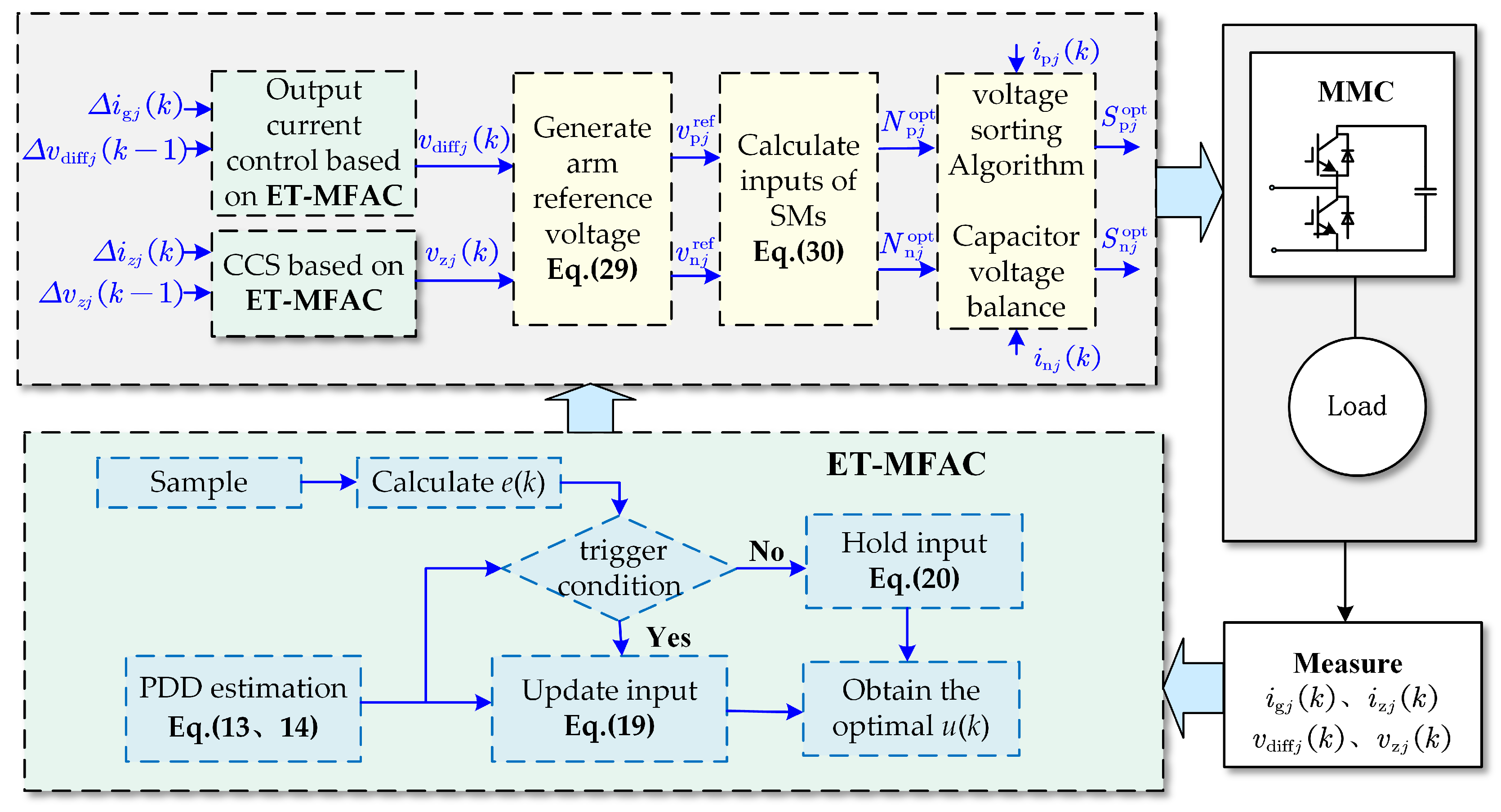
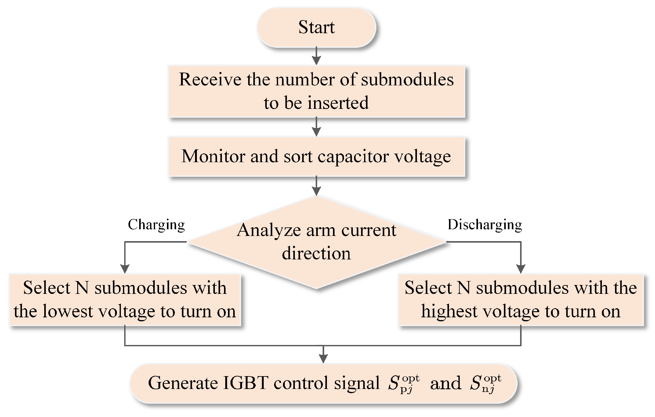
3. Proposed ET-MFAC Control for MMC

In this section, a model-free adaptive control with event-triggered mechanism method for MMC is proposed. This scheme eliminates the need for a mathematical model of and circuit parameters for the system. By leveraging online input–output data, it achieves robust control under system parameter mismatching. Furthermore, the introduction of the event-triggered mechanism effectively reduces the computational burden and switching losses, overcoming the traditional challenges encountered in FCS-MPC control. The proposed ET-MFAC control framework for MMC is illustrated in Figure 3.

3.1. Model-Free Adaptive Control

Consider a class of single-input–single-output (SISO) discrete-time nonlinear systems with unknown model parameters described by the following equation:
y k + 1 = h y k , , y k n y , u k , , u k n u
where  n y  and  n u  are positive integers representing the order of the equation, k denotes the k-th sampling instant, u represents the system input, and y represents the system output. Since the model structure is unknown, it is represented by the general function expression  h . , where  h . R m .
In accordance with the principles of model-free adaptive control, there exists a pseudo partial derivative (PDD)  φ k  that transforms a nonlinear system into a linear system based on the compact form dynamic linearization (CFDL) model [36]:
Δ y k + 1 = φ k Δ u k
To solve for the next control input, the following cost function is employed:
J u k = y ref k + 1 y k + 1 2 + λ Δ u k 2
where  λ > 0  is a penalty factor introduced to ensure smoothness and prevent excessively large control inputs.
Substituting Equation (9) into the cost function (10), differentiating the resulting function with respect to  u k , then setting the derivative to zero yields the control input algorithm for the next time step:
u k = u k 1 + ρ φ k λ + φ k 2 · y ref k + 1 y k
where  ρ ( 0 , 1 ]  is a step-size factor introduced to enhance the generality of the control input formula derived from the cost function.
As observed from the expression of the control input derived from the cost function, the value of  φ k  must be given before obtaining the control input. Traditional parameter estimation criteria functions typically minimize the squared error between the system model output and the actual output. However, parameter estimates derived from these criteria often exhibit rapid changes or excessive sensitivity to abrupt and/or inaccurately sampled data. To address these issues, a new estimation criteria function was proposed in [37] and is expressed as:
J φ k = y k y k 1 φ k Δ u k 1 2 + μ φ k φ k 1 2
where  μ > 0  is a weighting factor. The introduction of  μ φ k φ k 1 2  can effectively impose a limit on the range of variation of the time-varying parameter  φ .
Differentiating Equation (12) with respect to  φ k  and setting the derivative to zero leads to the estimation algorithm for  φ k :
φ k = φ k 1 + η Δ u k 1 μ + Δ u k 1 2 · Δ y k φ k 1 Δ u k 1
φ k = φ 1 , if Δ u k 1 ε or φ k ε or sign φ k sign φ 1
where  η ( 0 , 2 ]  represents a fixed step factor inserted to enhance the generality of the pseudo partial derivative estimation formula derived from the cost function. The term  ε  represents a tiny positive constant;  φ 1  represents the initial value of  φ k .
As can be seen from the derivation process above, this MFAC scheme only requires the online input–output data and operates without requiring explicit model parameter values. Therefore, it exhibits robustness in the case of parameter mismatching.

3.2. Event-Triggering Mechanism

To decrease the frequency of control algorithm execution while making sure that the tracking error,  y ˜ k = y ref k y k  stays within the predefined bounds, where  y ref k  represents the desired trajectory. If the trigger moment arrives, indicating that the triggering condition is met, the control input will be updated. Otherwise, it remains constant [38]. Defining the event-triggered error as:  e k = y ˜ k y ˜ k i 1 , where  k i 1  represents the previous event trigger time instant,  k i = k i 1 + n T s . Simultaneously, to ensure the tracking error converges to a satisfactory boundary, the event-triggered condition is introduced as follows:
| y ˜ ( k ) | θ or e 2 ( k ) > D ( k ) 2 φ 2 ( k ) P c 2 ( k )
where  D k = y ˜ 2 k 2 1 φ k P c k y ˜ k + Δ y ref k + 1 2 ρ c > 0 , and  λ c > 0 P c k = ρ c φ k / λ c + φ k 2 , and  ϑ > 0  is a constant representing the threshold of the tracking error. If the event-triggering condition (15) is satisfied, the system will update the control input at the next event-trigger time instant  k i  ( k i = k ).
Then, the control input can be expressed as:
u ( k ) = u ( k i 1 ) + P c ( k ) y ˜ ( k ) , k = k i u ( k i 1 ) , k ( k i 1 , k i )
Based on Equations (8) to (16), the ET-MFAC based control scheme is outlined in the following summary:
φ k = φ k 1 + η Δ u k 1 μ + Δ u k 1 2 · Δ y k φ k 1 Δ u k 1
φ k = φ 1 , if Δ u k 1 ε or φ k ε or sign φ k sign φ 1
if k = k i , u k = u k i 1 + P c k y ˜ k
if k k i 1 , k i , u k = u k i 1

3.3. Specific Design of ET-MFAC for MMC Applications

Based on the mathematical analysis in Section 2, Equation (6) reveals that the MMC output current control system can be regarded as a SISO discrete-time nonlinear system with the output AC current  i g j  as the output and the differential-mode voltage  v diff j  as the input. Referring to Equation (8) for the nonlinear system, the relationship between them is as follows:
i g j k + 1 = h i g j k , , i g j k n y , v diff j k , , v diff j k n u
Furthermore, there exists a pseudo partial derivative  φ 1 k  that transforms this nonlinear system into a linear system based on the CFDL model:
Δ i g j k + 1 = φ 1 k Δ v diff j k
Therefore, according to Equations (17) to (20), the ET-MFAC algorithm for output current tracking control can be derived as follows:
φ 1 k = φ 1 k 1 + η Δ v diff j k 1 μ + Δ v diff j k 1 2 · ( Δ i g j k φ 1 k 1 Δ v diff j k 1 ) φ 1 k = φ 1 1 , if Δ v diff j k 1 ε o r φ 1 k ε o r sign φ 1 k sign φ 1 1 v diff j k = v diff j k i 1 + P c k i ˜ g j k , k = k i v diff j k i 1 , k k i 1 , k i
Similarly, based on Equation (7), the circulating current suppression control system can be considered as a SISO discrete-time nonlinear system with the circulating current  i z j  as the output and  v z j  caused by circulating current as the input. Referring to the nonlinear system expression, it can be described as:
i g j k + 1 = h i g j k , , i g j k n y , v diff j k , , v diff j k n u
Similarly, there exists a pseudo partial derivative  φ 2  that transforms this nonlinear system into a linear system based on Equation (9):
Δ i z j k + 1 = φ 2 k Δ v z j k
Therefore, according to Equations (17) to (20), the ET-MFAC algorithm for circulating current suppression will be derived as follows:
φ 2 k = φ 2 k 1 + η Δ v z j k 1 μ + Δ v z j k 1 2 · Δ i z j k φ 2 k 1 Δ v z j k 1 φ 2 k = φ 2 1 , if Δ v z j k 1 ε o r φ 2 k ε o r sign φ 2 k sign φ 2 1 v z j k = v z j k i 1 + P c k i ˜ z j k , k = k i v z j k i 1 , k k i 1 , k i
Equations (23) and (26) reveal that the ET-MFAC control is solely influenced by the input and output current and voltage, with no direct dependence on the number of sub-modules. This observation lays the foundation for subsequent simulation studies using a smaller-scale MMC system.
Through Equations (23) and (26), the optimal differential voltage  v diff j k  for output current tracking and the optimal compensation voltage  v z j k  for circulating current suppression can be obtained.
Assuming that the circulating current voltage has been compensated, the following equation holds:
v diff j k = v n j k v p j k v dc = v n j k + v p j k
Based on Equations (27),  v n j k  and  v p j k  can be calculated as:
v n j k = v dc + v diff j k / 2 v p j k = v dc v diff j k / 2
To eliminate circulating current, an arm voltage compensation method is employed. Therefore, the reference values for upper arm voltages  v p j ref  and lower arm voltages  v n j ref  are set as:
v p j ref = v p j v z j = v dc v diff j / 2 v z j v n j ref = v n j v z j = v dc + v diff j / 2 v z j
Using the nearest level modulation algorithm, the numbers of inserted sub-modules are obtained as:
N p j opt = round v p j ref v dc / N N n j opt = round v n j ref v dc / N
where N is the total number of sub-modules inserted in the arm of each phase.
By sorting the capacitor voltages and considering the direction of the arm currents, the sub-module capacitor voltage balancing control algorithm is depicted in Figure 4.
This process generates optimal switching states  S p j opt  and  S n j opt  for the upper and lower arms of phase j during the current sampling period. Finally, these switching states are sent to each sub-module to control the device to turn it on and off. To illustrate the proposed algorithm more clearly, the control scheme for MMC is summarized in Algorithm 1.
Algorithm 1 Model-free adaptive control with event-triggered mechanism for MMC
Input: 
System parameters:  η , μ , ρ c , λ c , ϑ , ε ,
Initial values:  φ 1 ( 1 ) , φ 2 ( 1 ) ,
Measured values:  i g j ( k ) , v diff j ( k 1 ) , i z j ( k ) , v z j ( k 1 ) ,
Reference values:  i g j ref ( k ) , v dc , i z j ref ( k ) .
Output: 
Sub-module switching states:  S g j opt ( k ) , S n j opt ( k )
1:
Step1: Pseudo partial derivative estimation
2:
Calculate:  Δ v diff j ( k 1 ) Δ i g j ( k )
3:
  φ 1 ( k ) = φ 1 ( k 1 ) + η Δ v diff j ( k 1 ) μ + Δ v diff j ( k 1 ) 2 · ( Δ i g j ( k ) φ 1 ( k 1 ) Δ v diff j ( k 1 ) )
4:
if   | Δ v diff j ( k 1 ) | ε or | φ 1 ( k ) | ε or s i g n ( φ 1 ( k ) ) s i g n ( φ 1 ( 1 ) )  then
5:
φ 1 ( k ) = φ 1 ( 1 )
6:
end if
7:
Step2: Event-triggering mechanism
8:
Calculate  e ( k ) e ( k ) = i ˜ g j ( k i 1 ) i ˜ g j ( k )
9:
Calculate  P c ( k ) P c ( k ) = ρ c φ 1 ( k ) λ c + φ 1 ( k ) 2
10:
Calculate  D ( k ) D ( k ) = i ˜ g j ( k ) 2 2 ( ( 1 φ 1 ( k ) P c ( k ) ) i ˜ g j ( k ) + Δ i g j ref ( k + 1 ) ) 2
11:
if | i ˜ g j ( k ) | ϑ  or  e 2 ( k ) > D ( k ) 2 φ 1 ( k ) 2 P c ( k ) 2  then
12:
v diff j ( k ) = v diff j ( k i 1 ) + P c ( k ) i ˜ g j ( k )
13:
else
14:
v diff j ( k ) = v diff j ( k i 1 )
15:
end if
16:
Step3: Repeat Step1 and Step2
17:
Repeat Step1 to calculate  φ 2 ( k ) , {Replace  Δ i g j ( k ) , Δ v d i f f j ( k 1 )  with  Δ i z j ( k ) , Δ v z j ( k 1 ) }
18:
Repeat Step2 to calculate  v z j ( k ) , {Replace  i g j ( k ) i g j ref , φ 1 ( k ) , v diff j ( k 1 )  with  i z j ( k ) , i z j ref , φ 2 ( k ) , Δ v z j ( k 1 ) }
19:
Step4: Calculate number of inserted sub-modules
20:
  v n j ref ( k ) = ( v dc + v diff j ( k ) ) / 2 v z j ( k )
21:
  v p j ref ( k ) = ( v dc v diff j ( k ) ) / 2 v z j ( k )
22:
  N n j opt ( k ) = r o u n d v n j ref ( k ) v dc / N
23:
  N p j opt ( k ) = r o u n d v n j ref ( k ) v dc / N
24:
Step5: Output sub-module switching states with capacitor voltage balancing control
25:
Output  S n j opt ( k )  and  S p j opt ( k )  (assign a value of 1 or 0, depending on whether the SM is put into or cut off.)

4. Results and Analysis

To verify the correctness and effectiveness of the proposed ET-MFAC control strategy, a sample model is built in the MATLAB/Simulink simulation platform. The ET-MFAC scheme is compared with the computationally efficient PIR-MPC [39] and the classical FCS-MPC [12] from four aspects: steady-state performance, transient performance, steady-state performance under inductance mismatching, and the impact of the event-triggered mechanism on the computational burden. The main simulation parameters of the system are listed in Table 1. The sub-module capacitor and bridge arm inductor are key parameters for the MMC main circuit. The sub-module capacitor must have sufficient capacity to control voltage ripple, while the bridge arm inductor suppresses harmonics in the circulating current. The design methods for these parameters are detailed in [1,2], respectively. The design methods for these parameters can be found in [40,41], respectively.

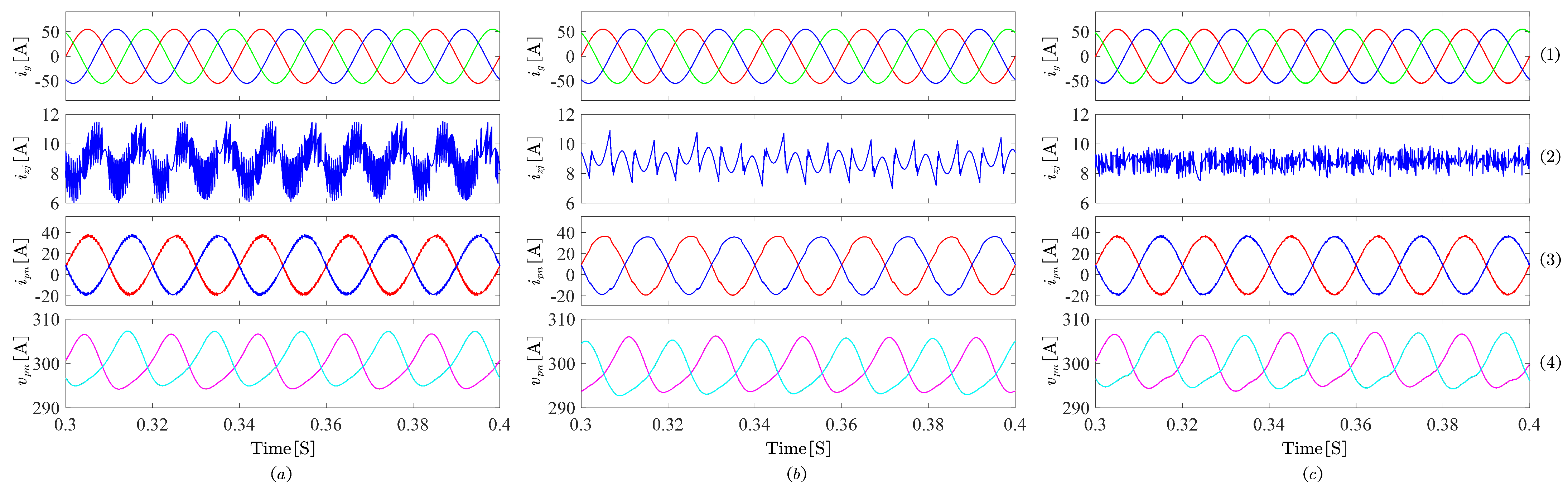
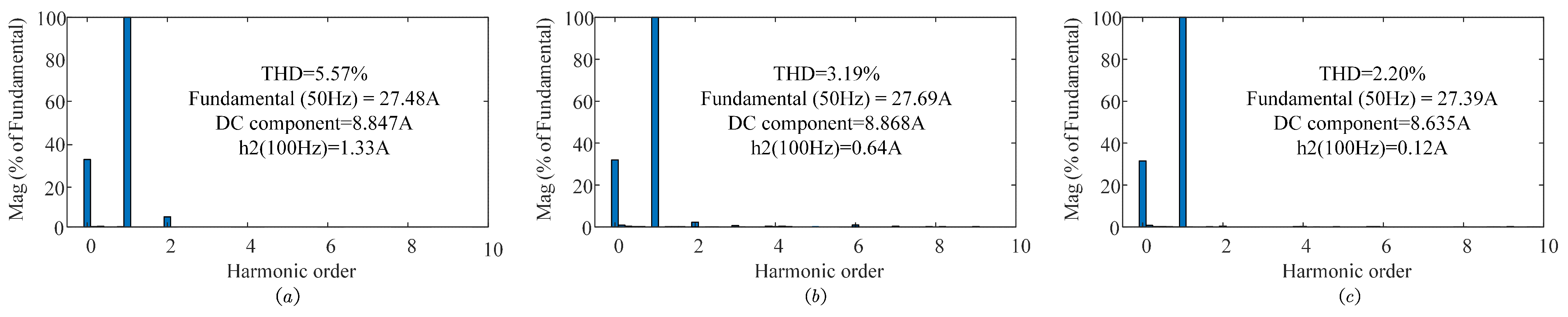
4.1. Steady-State Control Performance

Figure 5 illustrates the overall steady-state performance under the three different control schemes, including three-phase output currents, circulating currents, arm currents, and capacitor voltages.
With an output current reference set at 55 A, Figure 5(1) demonstrates that all three schemes achieve smooth and symmetrical tracking performance. With the sub-module capacitor voltage reference set at 300 V, Figure 5(4) shows that the capacitor voltages of each sub-module within a single arm exhibit consistent fluctuation patterns. The capacitor voltages of the upper and lower arms exhibit opposite fluctuation trends due to the complementary insertion and bypass states of SMs in the respective arms. The measured results indicate that the capacitor voltage fluctuation range is nearly identical under these three control strategies, ranging from 294 V to 307 V. All of them demonstrate good voltage balancing performance.
Taking into account the circulating current suppression capability, Figure 5(2,3) illustrate effective suppression of AC harmonic components, with the internal circulating current stabilizing around a DC component of approximately 8.8 A. Interestingly, Figure 6 reveals that the arm inductance current THD under FCS-MPC and PIR-MPC control is 5.57% and 3.19%, respectively, with second-order harmonic components of 1.33 A and 0.64 A. In contrast, ET-MFAC achieves a THD of only 2.20% and reduces the second-order harmonic component to 0.12 A, showcasing superior circulating current suppression performance.

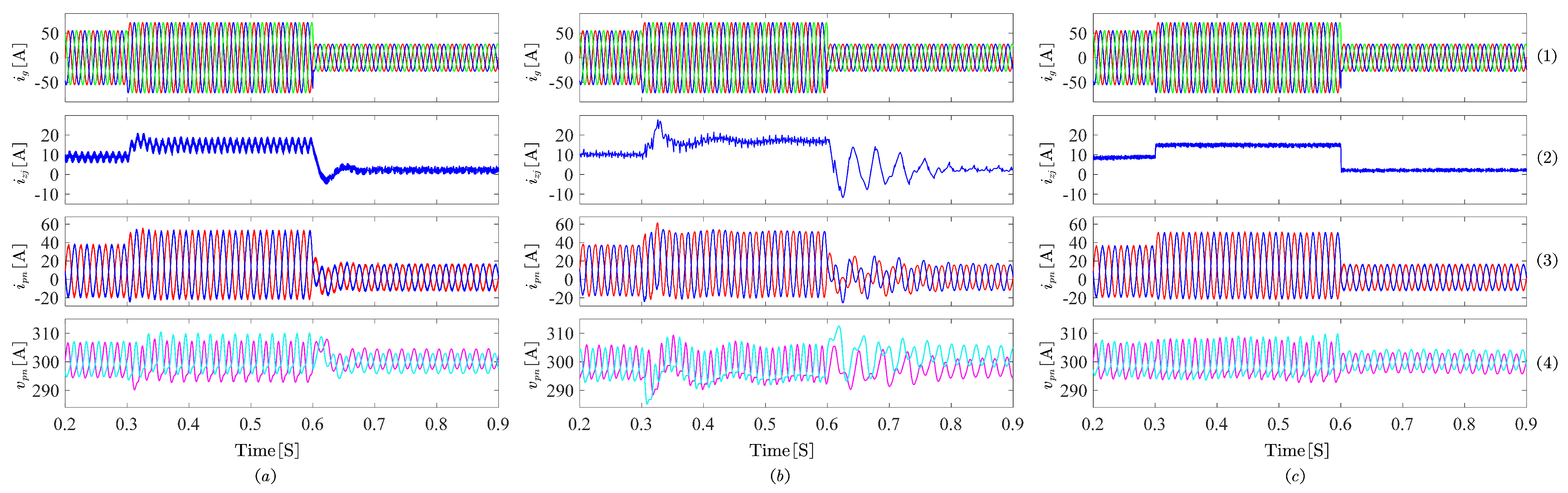
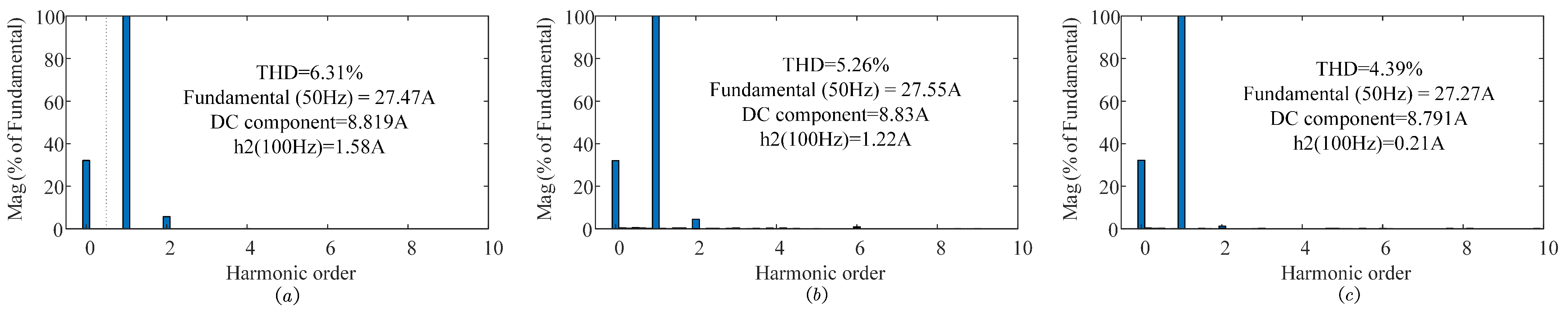
4.2. Dynamic-State Control Performance

During the simulation, after the system reaches steady state, the output current reference is subjected to a step change from 55 A to 72 A at 0.3 s and then reduces to 28 A at 0.6 s. As can be observed from Figure 7(1), all three methods achieve rapid and accurate tracking of the output current. As evident from Figure 7(2,3), the transient performance of PIR-MPC control significantly deteriorates during the current reduction phase, exhibiting a substantial circulating current overshoot and a prolonged settling time, requiring approximately seven cycles to reach stability. This excessive overshoot can exceed the system’s power limitations, potentially damaging components such as switching devices, filters, and transformers. Simultaneously, the circulating current under FCS-MPC control also displays reverse overshoot, with a settling time of around three cycles. In contrast, ET-MFAC control demonstrates superior dynamic performance. Regardless of whether the current is increasing or decreasing, its adjustment process exhibits minimal overshoot, achieving a stable state almost instantaneously. Moreover, as observed in Figure 7(4), the capacitor voltage fluctuation magnitude changes proportionally with the increase and decrease in current, with ET-MFAC exhibiting the smallest fluctuation range among the three control methods.

4.3. Steady-State Performance with the Effect of Parameter Mismatching

To evaluate the impact of parameter mismatching on steady-state performance, it is assumed that both the arm inductance and the output filter inductance deviate from their nominal values. Figure 8 illustrates the system’s steady-state waveforms when the nominal arm inductance is 2.5 mH while the actual arm inductance is 5 mH. It is evident that the inductance mismatch significantly affects the circulating current and arm current. The total harmonic distortion (THD) of the arm current is shown in Figure 9. As can be seen, the THD values generated by the FCS-MPC, PIR-MPC, and ET-MFAC control schemes are 6.31%, 5.26%, and 4.39%, respectively. Remarkably, ET-MFAC maintains the lowest harmonic performance even under parameter mismatching.
To better understand the effect of inductance mismatching on system performance, the THD of the arm current is measured for arm inductance values of 1, 2, 3, 5, 8, and 10 mH, demonstrating the impact of inductance on current quality. The results are presented in Figure 10a. Firstly, it is clear that the THD decreases with increasing arm inductance for all methods. This observation aligns with expectations, as higher inductance values generally filter out high-frequency harmonic signals. Secondly, ET-MFAC consistently exhibits the lowest THD across all inductance values, indicating that even under parameter mismatching, ET-MFAC demonstrates superior performance in suppressing harmonics compared to FCS-MPC and MPC-PIR. Lastly, a significant increase in the THD is observed when the arm inductance is 1 mH. This highlights the system’s sensitivity to parameter deviations, emphasizing the critical importance of selecting appropriate values.
The impact of output filter inductance mismatching is investigated, too. With the actual inductance value being 10 mH, tests were conducted with inductance values of 1, 4, 7, 13, and 15 mH. The results, illustrated in Figure 10b, demonstrate the performance of ET-MFAC, PIR-MPC, and FCS-MPC. ET-MFAC exhibits the most favorable performance, achieving the lowest THD across the tested inductance range. Specifically, the THD under ET-MFAC control consistently decreases with increasing inductance, ranging from 2.97% to 2.04%. This indicates its superior ability to mitigate the adverse effects of inductance mismatching and to enhance power quality. In contrast, FCS-MPC shows a trend of initial THD reduction followed by an increase as the inductance deviates further from the nominal value. PIR-MPC maintains a relatively stable THD, ranging from 3.39% to 3.12%, while FCS-MPC exhibits a larger variation, with THD ranging from 5.45% to 6.36%. Overall, ET-MFAC demonstrates superior performance in mitigating THD under inductance mismatch conditions. It effectively adapts to the varying inductance and consistently reduces the THD, contributing to improved power quality. While PIR-MPC and FCS-MPC demonstrate some adaptability to inductance variations, their effectiveness in controlling the THD is comparatively limited.

4.4. The Impact of the ET Mechanism on the Computational Burden

Figure 11 illustrates the pulse signals and their locally magnified details under three different control schemes. It is evident that the ET-MFAC method exhibits a lower wave-form density, effectively reducing the number of switching actions. Within the simulation model, the average switching frequency during the 0–0.4 s simulation time was measured for each method. FCS-MPC resulted in 10,650 switching actions, while PIR-MPC achieved a reduction of 660 actions (approximately 6%), totaling 9990 actions. Notably, ET-MFAC exhibited the lowest switching frequency with 8625 actions: a significant reduction of 2025 actions (19%) compared to FCS-MPC and 1365 actions (12%) compared to PIR-MPC.
To clearly illustrate the computational burden of these three control schemes, the total simulation time was set to 0.4 s, with a control cycle of  1 × 10 5  s. The average execution time of the control program per cycle was measured and is presented in Table 2.
As shown in Table 2, the ET-MFAC control program exhibits the shortest execution time: approximately one-fifth that of FCS-MPC. PIR-MPC follows, while FCS-MPC has the longest execution time. This is attributed to the simpler data model employed by ET-MFAC and its avoidance of multiple predictions and rolling optimizations within a control cycle as required by the FCS-MPC algorithm. This significantly enhances the computational efficiency of ET-MFAC.
These results demonstrate that ET-MFAC effectively reduces the computational burden and switching losses of the system while ensuring satisfactory control performance. This highlights its advantage in applications where minimizing switching actions and associated losses is crucial.

5. Conclusions

To enhance the computational performance and robustness in multi-objective control of modular multilevel converters, this paper proposes a control scheme based on model-free adaptive control with an event-triggered mechanism. Simulation results demonstrate the superiority of the proposed method in four key aspects: (1) Improved steady-state performance: ET-MFAC is more effective in suppressing circulating current and reducing harmonic distortion, achieving a second harmonic content of only 2.20%, which is 3.27% lower than Fast FCS-MPC from [13]. (2) Enhanced dynamic performance: the ET-MFAC scheme demonstrates robust adaptability to sudden changes in output power or current, exhibiting the shortest response time and minimal overshoot among the three schemes. (3) Improved robustness: the ET-MFAC scheme maintains low total harmonic distortion (THD) and normal operation even under mismatched inductance parameters, demonstrating its superior robustness to parameter variations. (4) Increased computational efficiency: the proposed control scheme exhibits the lowest control program execution time and switching frequency; compared to Fast FCS-MPC, the execution time is reduced by 20%, and the switching frequency is reduced by 19%.
Comparative simulations with two other control schemes validate the efficiency and unique characteristics of the proposed EF-MFAC method. However, practical applications may encounter measurement errors and noise during data acquisition, and steady-state voltage fluctuations remain a concern. Future work will focus on enhancing the system control scheme to mitigate these factors.

Author Contributions

Conceptualization, Y.F.; Methodology, Y.F.; Software, S.S.; Validation, Y.F.; Resources, Y.L. and A.F.; Data curation, Y.L.; Writing—original draft, Y.F.; Visualization, A.F.; Supervision, Y.L.; Project administration, Z.Z. All authors have read and agreed to the published version of the manuscript.

Funding

This work was supported by the General Program of the National Natural Science Foundation of China under grant 52307213.

Data Availability Statement

The original contributions presented in the study are included in the article, further inquiries can be directed to the corresponding author.

Conflicts of Interest

Author Shuo Shi was employed by the company State Grid Shandong Electric Power Research Institute. The remaining authors declare that the research was conducted in the absence of any commercial or financial relationships that could be construed as a potential conflict of interest.

References

  1. Nami, A.; Liang, J.; Dijkhuizen, F.; Demetriades, G.D. Modular Multilevel Converters for HVDC Applications: Review on Converter Cells and Functionalities. IEEE Trans. Power Electron. 2015, 30, 18–36. [Google Scholar] [CrossRef]
  2. Martinez-Rodrigo, F.; Ramirez, D.; Rey-Boue, A.B.; De Pablo, S.; Herrero-de Lucas, L.C. Modular multilevel converters: Control and applications. Energies 2017, 10, 1709. [Google Scholar] [CrossRef]
  3. Harbi, I.; Rodriguez, J.; Liegmann, E.; Makhamreh, H.; Heldwein, M.L.; Novak, M.; Rossi, M.; Abdelrahem, M.; Trabelsi, M.; Ahmed, M.; et al. Model-Predictive Control of Multilevel Inverters: Challenges, Recent Advances, and Trends. IEEE Trans. Power Electron. 2023, 38, 10845–10868. [Google Scholar] [CrossRef]
  4. Moon, J.W.; Park, J.W.; Kang, D.W.; Kim, J.M. A Control Method of HVDC-Modular Multilevel Converter Based on Arm Current Under the Unbalanced Voltage Condition. IEEE Trans. Power Deliv. 2015, 30, 529–536. [Google Scholar] [CrossRef]
  5. Li, M.; Chang, X.; Dong, N.; Liu, S.; Yang, H.; Zhao, R. Arm-Current-Based Model Predictive Control for Modular Multilevel Converter Under Unbalanced Grid Conditions. IEEE J. Emerg. Sel. Top. Power Electron. 2022, 10, 3195–3206. [Google Scholar] [CrossRef]
  6. Jiang, Y.; Wang, W.; Shu, H.; Zhang, J. Model Predictive PI Circulating Current Control for Modular Multilevel Converter. Electronics 2023, 12, 2690. [Google Scholar] [CrossRef]
  7. Ramirez, D.; Zarei, M.E.; Gupta, M.; Serrano, J. Fast Model-based Predictive Control (FMPC) for Grid Connected Modular Multilevel Converters (MMC). Int. J. Electr. Power Energy Syst. 2020, 119, 105951. [Google Scholar] [CrossRef]
  8. Perez, M.A.; Ceballos, S.; Konstantinou, G.; Pou, J.; Aguilera, R.P. Modular Multilevel Converters: Recent Achievements and Challenges. IEEE Open J. Ind. Electron. Soc. 2021, 2, 224–239. [Google Scholar] [CrossRef]
  9. Yue, B.; Cheng, Q.; Cheng, Y. Robustness Improvement Model Predictive Control Strategy Based on Luenberger Observer for Y-type Modular Multilevel Converter. Int. J. Circuit Theory Appl. 2023, 51, 5672–5690. [Google Scholar] [CrossRef]
  10. Wang, J.; Tang, Y.; Lin, P.; Liu, X.; Pou, J. Deadbeat Predictive Current Control for Modular Multilevel Converters With Enhanced Steady-State Performance and Stability. IEEE Trans. Power Electron. 2020, 35, 6878–6894. [Google Scholar] [CrossRef]
  11. Liu, P.; Wang, Y.; Cong, W.; Lei, W. Grouping-Sorting-Optimized Model Predictive Control for Modular Multilevel Converter With Reduced Computational Load. IEEE Trans. Power Electron. 2016, 31, 1896–1907. [Google Scholar] [CrossRef]
  12. Gong, Z.; Dai, P.; Yuan, X.; Wu, X.; Guo, G. Design and Experimental Evaluation of Fast Model Predictive Control for Modular Multilevel Converters. IEEE Trans. Ind. Electron. 2016, 63, 3845–3856. [Google Scholar] [CrossRef]
  13. Guo, P.; He, Z.; Yue, Y.; Xu, Q.; Huang, X.; Chen, Y.; Luo, A. A Novel Two-Stage Model Predictive Control for Modular Multilevel Converter With Reduced Computation. IEEE Trans. Ind. Electron. 2019, 66, 2410–2422. [Google Scholar] [CrossRef]
  14. Wang, B.; Huang, J.; Wen, C.; Rodriguez, J.; Garcia, C.; Gooi, H.B. Event-Triggered Model Predictive Control for Power Converters. IEEE Trans. Ind. Electron. 2021, 68, 715–720. [Google Scholar] [CrossRef]
  15. Kwak, S.; Moon, U.C.; Park, J.C. Predictive-Control-Based Direct Power Control With an Adaptive Parameter Identification Technique for Improved AFE Performance. IEEE Trans. Power Electron. 2014, 29, 6178–6187. [Google Scholar] [CrossRef]
  16. Liu, X.; Wang, D.; Peng, Z. Improved Finite-Control-Set Model Predictive Control for Active Front-End Rectifiers with Simplified Computational Approach and on-Line Parameter Identification. ISA Trans. 2017, 69, 51–64. [Google Scholar] [CrossRef]
  17. El Myasse, I.; Mansouri, A.; El Magri, A.; Watil, A.; Kissaoui, M.; Lajouad, R.; Ashfaq, S.; Elaadouli, N. Robust Nonlinear Control Design of MMC-HVDC Systems for Wind Power Plants Integration. In Proceedings of the 2023 3rd International Conference on Innovative Research in Applied Science, Engineering and Technology (IRASET), Mohammedia, Morocco, 18–19 May 2023; pp. 1–5. [Google Scholar]
  18. Mehreganfar, M.; Saeedinia, M.H.; Davari, S.A.; Garcia, C.; Rodriguez, J. Sensorless Predictive Control of AFE Rectifier With Robust Adaptive Inductance Estimation. IEEE Trans. Ind. Inform. 2019, 15, 3420–3431. [Google Scholar] [CrossRef]
  19. Li, Y.; Li, Y.; Wang, Q. Robust Predictive Current Control with Parallel Compensation Terms Against Multi-Parameter Mismatches for PMSMs. IEEE Trans. Energy Convers. 2020, 35, 2222–2230. [Google Scholar] [CrossRef]
  20. Yu, K.; Wang, Z. Online Decoupled Multi-Parameter Identification of Dual Three-Phase IPMSM Under Position-Offset and HF Signal Injection. IEEE Trans. Ind. Electron. 2024, 71, 3429–3440. [Google Scholar] [CrossRef]
  21. Zhang, Y.; Jin, J.; Huang, L. Model-Free Predictive Current Control of PMSM Drives Based on Extended State Observer Using Ultralocal Model. IEEE Trans. Ind. Electron. 2021, 68, 993–1003. [Google Scholar] [CrossRef]
  22. Zhang, Y.; Liu, X.; Liu, J.; Rodriguez, J.; Garcia, C. Model-Free Predictive Current Control of Power Converters Based on Ultra-Local Model. In Proceedings of the 2020 IEEE International Conference on Industrial Technology (ICIT), Buenos Aires, Argentina, 26–28 February 2020; pp. 1089–1093. [Google Scholar]
  23. Pal, P.; Behera, R.K.; Muduli, U.R. Eliminating Current Sensor Dependencies in DAB Converters Using a Luenberger Observer-Based Hybrid Approach. IEEE Trans. Ind. Appl. 2024, 60, 6380–6392. [Google Scholar] [CrossRef]
  24. Al-Wedami, A.; Al-Hosani, K.; Beig, A.R. Sliding Mode Observer of Submodular Capacitor Voltages in Modular Multilevel Converter. In Proceedings of the 2015 International Workshop on Recent Advances in Sliding Modes (RASM), Istanbul, Turkey, 9–11 April 2015; pp. 1–6. [Google Scholar]
  25. Chakraborty, R.; Samantaray, J.; Dey, A.; Chakrabarty, S. Capacitor Voltage Estimation of MMC Using a Discrete-Time Sliding Mode Observer Based on Discrete Model Approach. IEEE Trans. Ind. Appl. 2022, 58, 494–504. [Google Scholar] [CrossRef]
  26. Maysse, I.E.; Magri, A.E.; Watil, A.; Alkuhayli, A.; Kissaoui, M.; Lajouad, R.; Giri, F.; Mahmoud, M.M. Nonlinear Observer-Based Controller Design for VSC-Based HVDC Transmission Systems Under Uncertainties. IEEE Access 2023, 11, 124014–124030. [Google Scholar] [CrossRef]
  27. Liu, X.; Qiu, L.; Wu, W.; Ma, J.; Wang, D.; Peng, Z.; Fang, Y. Finite-time ESO-based cascade-free FCS-MPC for NNPC converter. Int. J. Electr. Power Energy Syst. 2023, 148, 108939. [Google Scholar] [CrossRef]
  28. Babayomi, O.; Zhang, Z. Model-Free Predictive Control of Power Converters with Multifrequency Extended State Observers. IEEE Trans. Ind. Electron. 2023, 70, 11379–11389. [Google Scholar] [CrossRef]
  29. Liu, X.; Qiu, L.; Wu, W.; Ma, J.; Fang, Y.; Peng, Z.; Wang, D. Predictor-Based Neural Network Finite-Set Predictive Control for Modular Multilevel Converter. IEEE Trans. Ind. Electron. 2021, 68, 11621–11627. [Google Scholar] [CrossRef]
  30. Liu, X.; Qiu, L.; Rodriguez, J.; Wu, W.; Ma, J.; Peng, Z.; Wang, D.; Fang, Y. Neural Predictor-Based Dynamic Surface Predictive Control for Power Converters. IEEE Trans. Ind. Electron. 2023, 70, 1057–1065. [Google Scholar] [CrossRef]
  31. Liu, X.; Qiu, L.; Fang, Y.; Wang, K.; Li, Y.; Rodríguez, J. Predictive Control of Voltage Source Inverter: An Online Reinforcement Learning Solution. IEEE Trans. Ind. Electron. 2024, 71, 6591–6600. [Google Scholar] [CrossRef]
  32. Xi, Q.; Tian, Y.; Fan, Y. Capacitor Voltage Balancing Control of MMC Sub-Module Based on Neural Network Prediction. Electronics 2024, 13, 795. [Google Scholar] [CrossRef]
  33. Liu, X.; Qiu, L.; Fang, Y.; Wang, K.; Li, Y.; Rodriguez, J. A Fuzzy Approximation for FCS-MPC in Power Converters. IEEE Trans. Power Electron. 2022, 37, 9153–9163. [Google Scholar] [CrossRef]
  34. Wu, W.; Qiu, L.; Liu, X.; Guo, F.; Rodriguez, J.; Ma, J.; Fang, Y. Data-Driven Iterative Learning Predictive Control for Power Converters. IEEE Trans. Power Electron. 2022, 37, 14028–14033. [Google Scholar] [CrossRef]
  35. Wu, W.; Qiu, L.; Rodriguez, J.; Liu, X.; Ma, J.; Fang, Y. Data-Driven Finite Control-Set Model Predictive Control for Modular Multilevel Converter. IEEE J. Emerg. Sel. Top. Power Electron. 2023, 11, 523–531. [Google Scholar] [CrossRef]
  36. Hou, Z.; Jin, S. A Novel Data-Driven Control Approach for a Class of Discrete-Time Nonlinear Systems. IEEE Trans. Control. Syst. Technol. 2011, 19, 1549–1558. [Google Scholar] [CrossRef]
  37. Hou, Z.; Zhu, Y. Controller-Dynamic-Linearization-Based Model Free Adaptive Control for Discrete-Time Nonlinear Systems. IEEE Trans. Ind. Inform. 2013, 9, 2301–2309. [Google Scholar] [CrossRef]
  38. Lin, N.; Chi, R.; Huang, B. Event-Triggered Model-Free Adaptive Control. IEEE Trans. Syst. Man Cybern. Syst. 2021, 51, 3358–3369. [Google Scholar] [CrossRef]
  39. Fang, Y.; Xu, N.; Liu, Y. Hybrid Linear Predictive Control Scheme Based on PIR and MPC for MMC. In Proceedings of the 2023 IEEE 2nd International Power Electronics and Application Symposium (PEAS), Guangzhou, China, 10–13 November 2023; pp. 491–495. [Google Scholar]
  40. Tu, Q.; Xu, Z.; Xu, L. Reduced Switching-Frequency Modulation and Circulating Current Suppression for Modular Multilevel Converters. IEEE Trans. Power Deliv. 2011, 26, 2009–2017. [Google Scholar]
  41. Tu, Q.; Xu, Z.; Huang, H.; Zhang, J. Parameter Design Principle of the Arm Inductor in Modular Multilevel Converter Based HVDC|IEEE Conference Publication|IEEE Xplore. Available online: https://ieeexplore.ieee.org/abstract/document/5666416 (accessed on 13 December 2010).
Figure 1. Three-phase topology of MMC.
Electronics 13 02899 g001
Figure 2. Single-phase equivalent circuit of MMC.
Electronics 13 02899 g002
Figure 3. Overall control structure of proposed ET-MFAC for MMC.
Electronics 13 02899 g003
Figure 4. Capacitor voltage balancing control algorithm.
Electronics 13 02899 g004
Figure 5. Steady-state control performance: (a) FCS-MPC method. (b) Hybrid PIR-MPC method. (c) Proposed ET-MFAC method.
Electronics 13 02899 g005
Figure 6. The THD of the arm current: (a) FCS-MPC method. (b) Hybrid PIR-MPC method. (c) Proposed ET-MFAC method.
Electronics 13 02899 g006
Figure 7. Dynamic-state control performance: (a) FCS-MPC method. (b) Hybrid PIR-MPC method. (c) Proposed ET-MFAC method.
Electronics 13 02899 g007
Figure 8. Steady-state control performance under parameter mismatching ( L arm = 2.5 mH ): (a) FCS-MPC method. (b) Hybrid PIR-MPC method. (c) Proposed ET-MFAC method.
Electronics 13 02899 g008
Figure 9. THD of arm current under parameter mismatching ( L arm = 2.5 mH ): (a) FCS-MPC method. (b) Hybrid PIR-MPC method. (c) Proposed ET-MFAC method.
Electronics 13 02899 g009
Figure 10. THD changes of three different control schemes under parameter mismatching: (a) The THD changes under the arm inductor mismatching. (b) The THD changes under the output filter inductor mismatching.
Electronics 13 02899 g010
Figure 11. Switching frequency performance: (a) FCS-MPC method. (b) Hybrid PIR-MPC method. (c) Proposed ET-MFAC method.
Electronics 13 02899 g011
Table 1. Simulation parameters of MMC system.
ParameterValue
DC-link voltage  U dc 1200 V
Arm Inductance  L arm 5 mH
Load resistance  R g Ω
Load inductance  L g 10 mH
Sub-module capacitance  C SM 6000 uF
Number of sub-modules per arm N4
Sub-module capacitor voltage  U c ref 300 V
AC-side output frequency f50 Hz
Table 2. Comparison of computational burden for different control methods.
MethodControl Program Cycle Time
FCS-MPC method 10.72 × 10 7 s
Hybrid PIR-MPC method 6.71 × 10 7 s
Proposed ET-MFAC method 1.94 × 10 7 s
Disclaimer/Publisher’s Note: The statements, opinions and data contained in all publications are solely those of the individual author(s) and contributor(s) and not of MDPI and/or the editor(s). MDPI and/or the editor(s) disclaim responsibility for any injury to people or property resulting from any ideas, methods, instructions or products referred to in the content.

