
A Full Calibration Approach on a Drone-Borne Platform for HF Antenna Measurements in Smart Grid Energy Facilities


Abstract
:1. Introduction
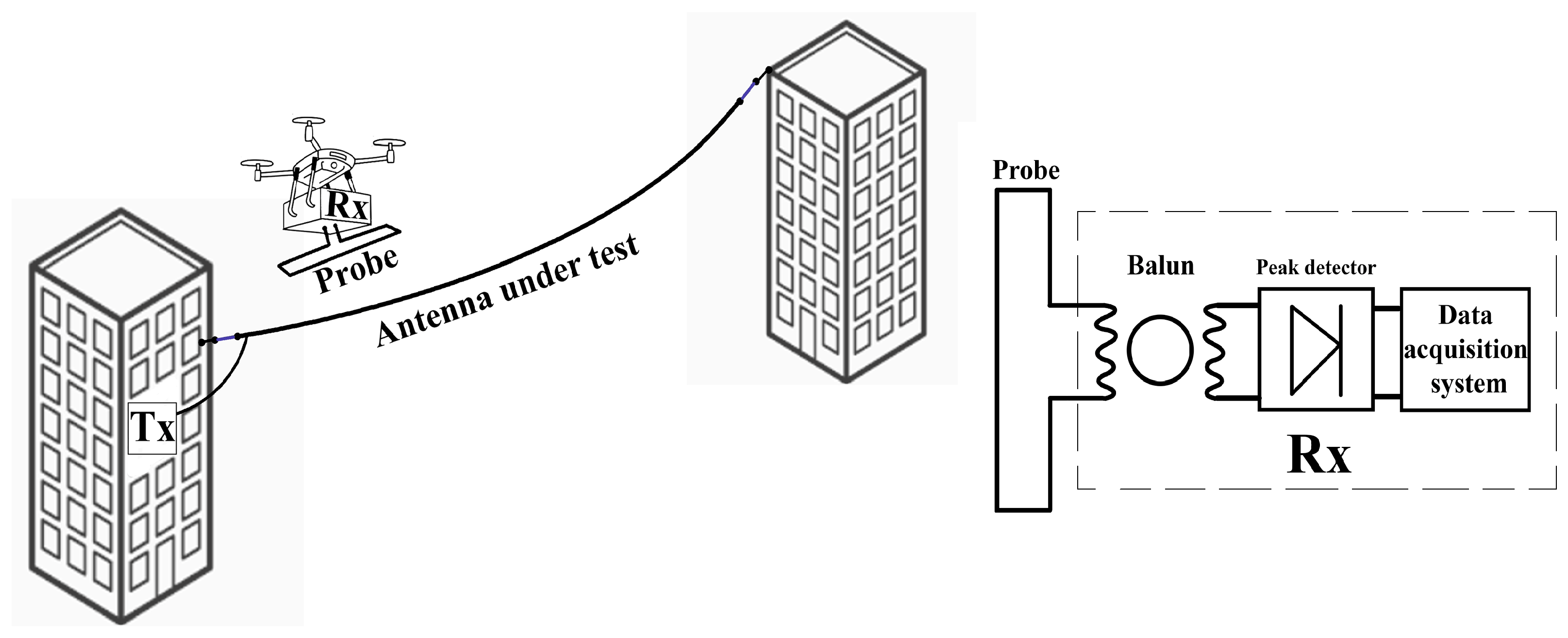
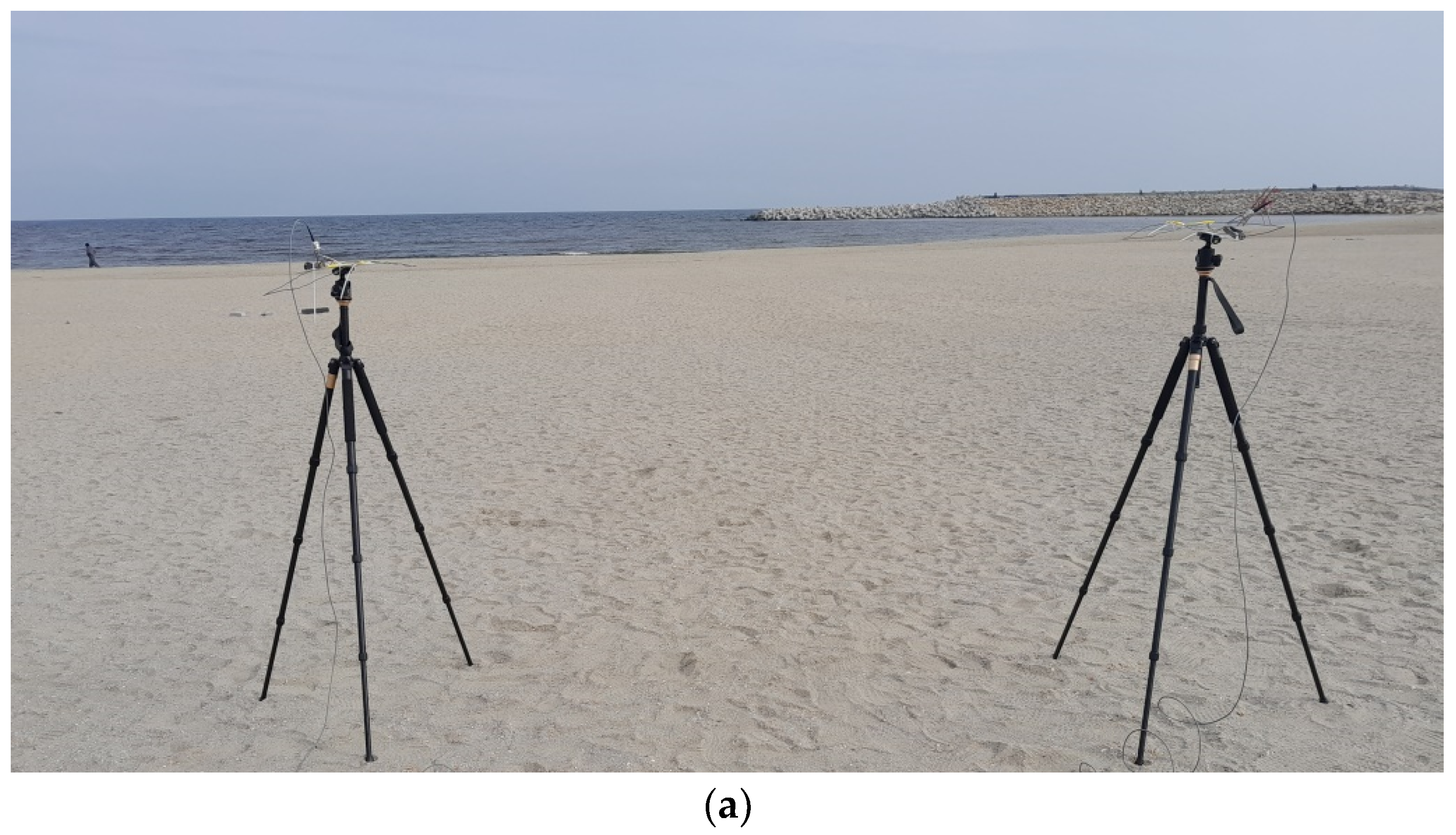
2. Platform Design
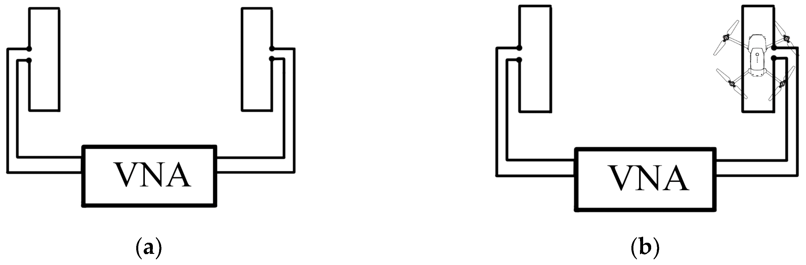
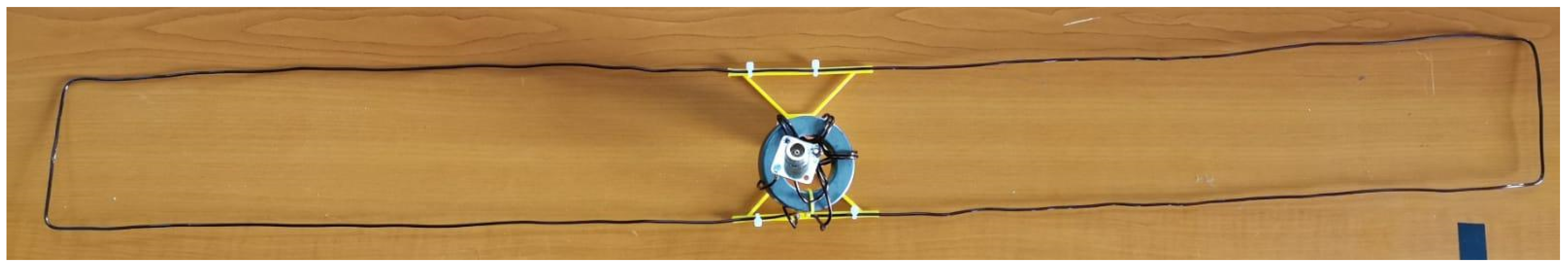
3. Probe Design and Calibration
4. Results
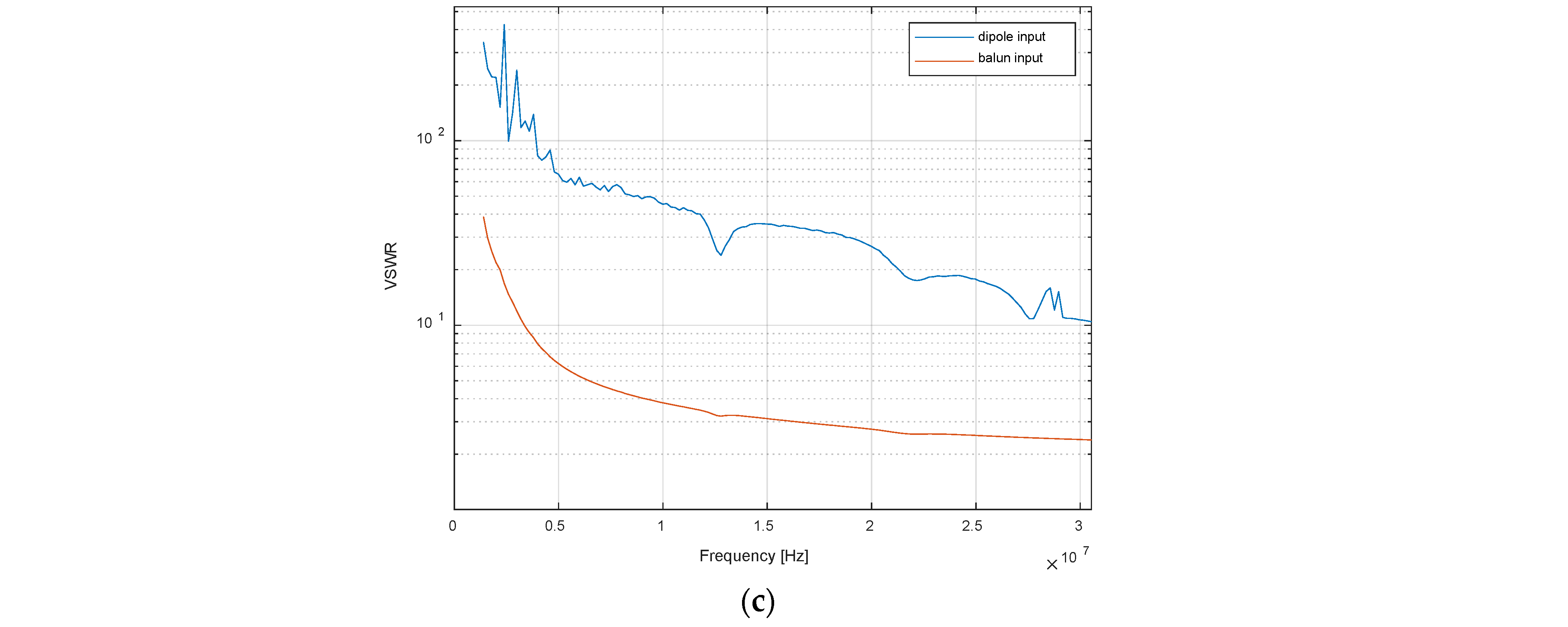
4.1. Antenna Input Characteristics
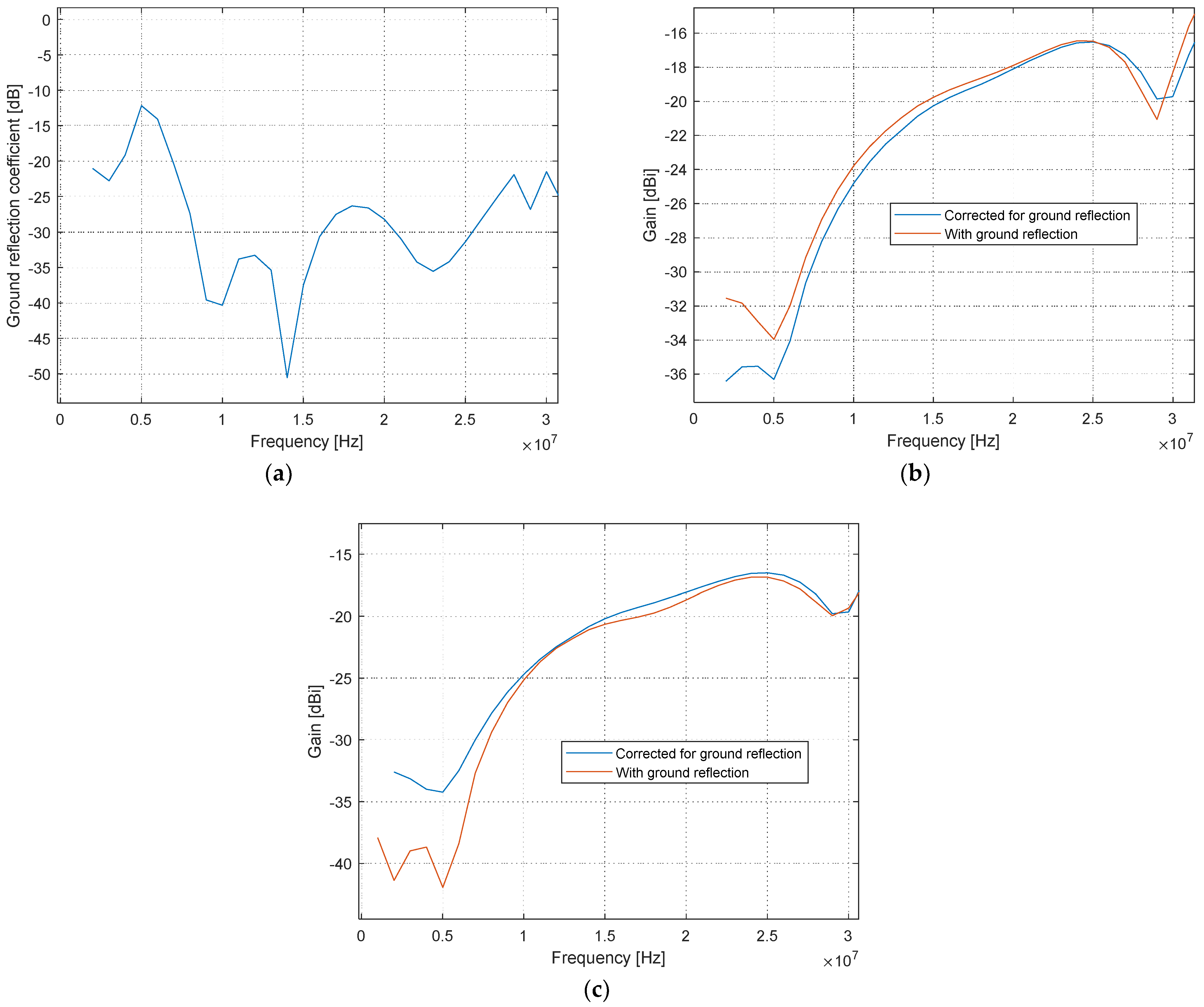
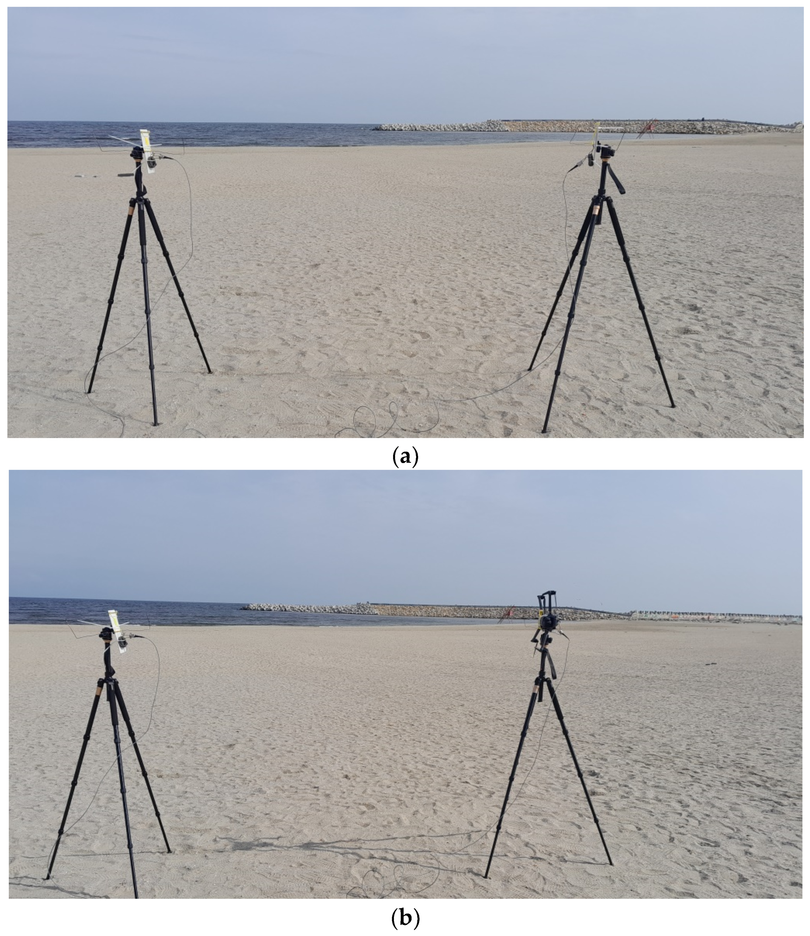
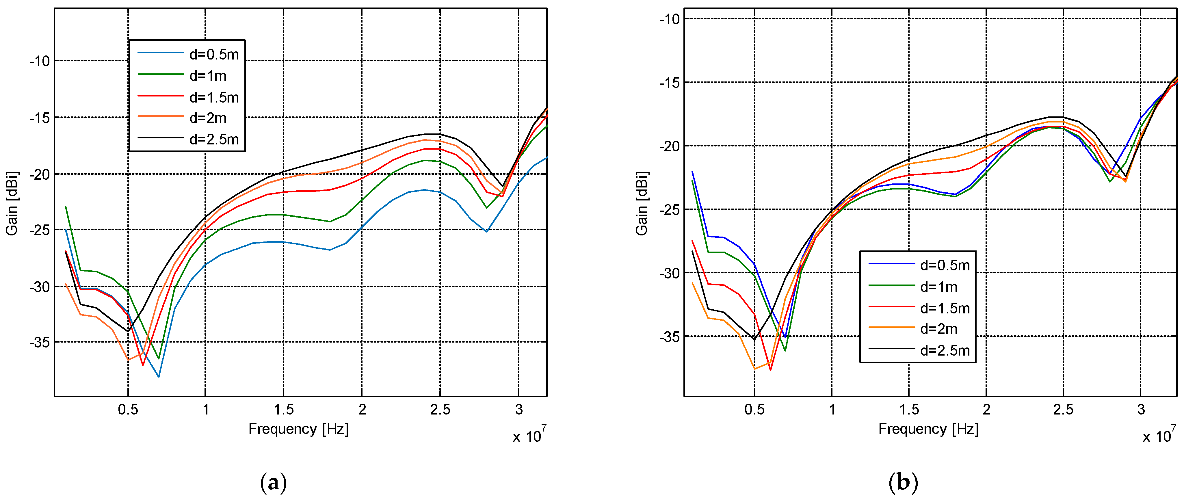
4.2. Ground Reflection
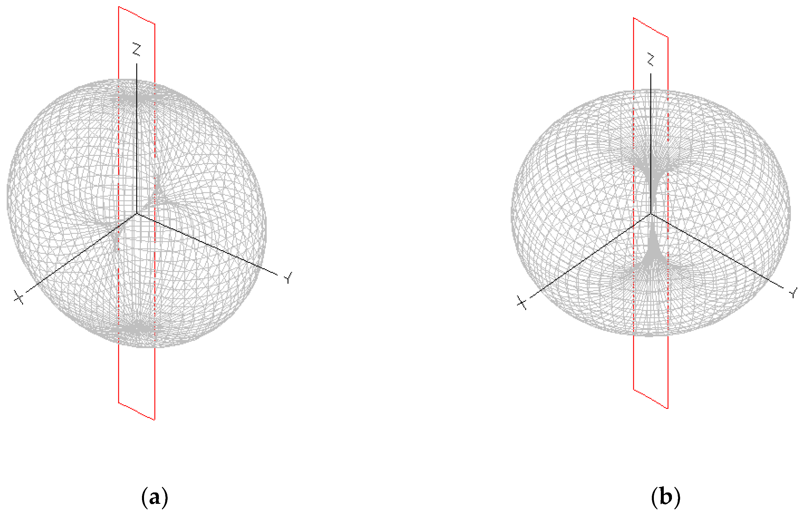
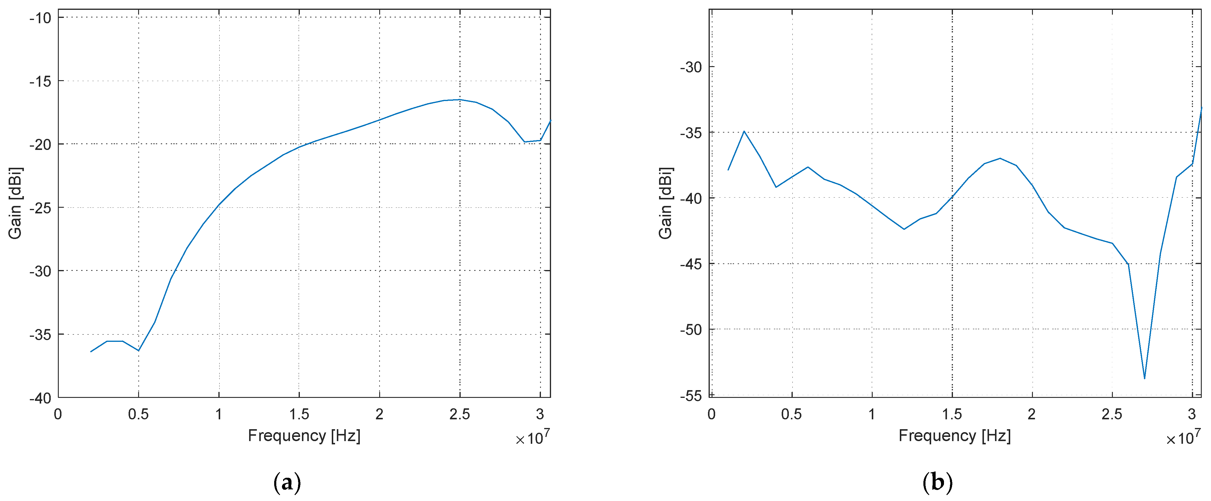
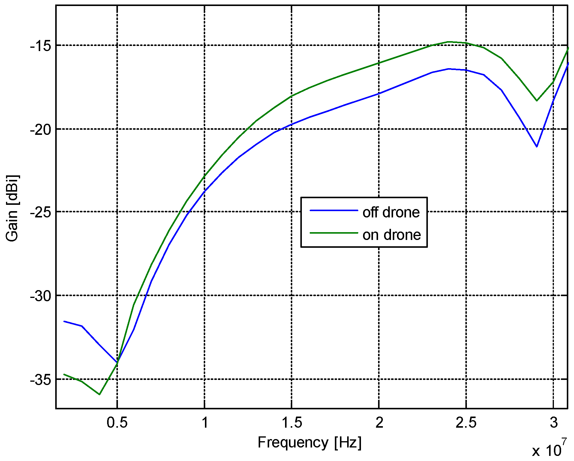
4.3. Probe Calibration with Field-Zone Correction and On-Drone Measurements
5. Conclusions
Author Contributions
Funding
Data Availability Statement
Conflicts of Interest
References
- Ohanu, C.P.; Rufai, S.A.; Oluchi, U.C. A comprehensive review of recent developments in smart grid through renewable energy resources integration. Heliyon 2024, 10, e25705. [Google Scholar] [CrossRef] [PubMed]
- Kabeyi, M.J.B.; Olanrewaju, O.A. Smart grid technologies and application in the sustainable energy transition: A review. Int. J. Sustain. Energy 2023, 42, 685–758. [Google Scholar] [CrossRef]
- Zhang, Z.; Peng, T.; Yang, K.; Li, X. Trajectory Optimization and Retrieving Monitory System for UAV-assisted Offshore Maritime Communications. In Proceedings of the 2023 3rd International Conference on Electronic Information Engineering and Computer Science (EIECS), Changchun, China, 22–24 September 2023; pp. 1014–1019. [Google Scholar] [CrossRef]
- Koziniec, T.; Murray, D.; Dixon, M. Precomputed Ionospheric Propagation for HF Wireless Sensor Transmission Scheduling. In Proceedings of the 2021 29th International Symposium on Modeling, Analysis, and Simulation of Computer and Telecommunication Systems (MASCOTS), Virtual Conference, 3–5 November 2021; pp. 1–8. [Google Scholar] [CrossRef]
- Marti-Puig, P.; Serra-Serra, M.; Bolaño, R.R. Low Complex Wireless Sensor Network Uplink in the HF band. April 2008. [Online]. Available online: https://upcommons.upc.edu/handle/2099/4925 (accessed on 3 June 2024).
- WSJT-X User Guide. [Online]. Available online: https://wsjt.sourceforge.io/wsjtx-doc/wsjtx-main-2.6.1.html (accessed on 14 March 2024).
- Parkins, W.A. Propagation Management for No-Acknowledge HF Communications Links. 1986. Available online: https://ui.adsabs.harvard.edu/abs/1986MsT..........5P (accessed on 14 March 2024).
- HF_radio_GM _ISPACG_Ver1.pdf. [Online]. Available online: https://www.icao.int/APAC/documents/edocs/cns/HF_radio_GM%20_ISPACG_Ver1.pdf (accessed on 23 May 2024).
- Tan, X.; Su, S.; Sun, X. Research on Narrowband Interference Suppression Technology of UAV Network Based on Spread Spectrum Communication. In Proceedings of the 2020 IEEE International Conference on Artificial Intelligence and Information Systems (ICAIIS), Dalian, China, 20–22 March 2020; pp. 335–338. [Google Scholar] [CrossRef]
- Tamas, R.D.; Babour, L.; Fond, E.; Slamnoiu, G.; Chilo, J.; Saguet, P. Cylindrical dipoles as ultra-wide band antennas: An energy-based analysis. Microw. Opt. Technol. Lett. 2008, 50, 917–921. [Google Scholar] [CrossRef]
- Bostan, S.M.; Urbina, J.V.; Mathews, J.D.; Bilén, S.G.; Breakall, J.K. An HF Software-Defined Radar to Study the Iono-sphere. Radio Sci. 2019, 54, 839–849. [Google Scholar] [CrossRef]
- Wicaksono, A.; Mauludiyanto, A.; Hendrantoro, G. An HF Digital Communication System Based on Software-Defined Radio. In Proceedings of the 2020 International Conference on Smart Technology and Applications (ICoSTA), Surabaya, Indonesia, 20 February 2020; pp. 1–5. [Google Scholar] [CrossRef]
- Belgibaev, R.R.; Ivanov, V.A.; Ivanov, D.V.; Laschevsky, A.R. Software-Defined Radio Ionosonde for Diagnostics of Wideband HF Channels with the Use of USRP Platform. In Proceedings of the 2019 Wave Electronics and its Application in Information and Telecommunication Systems (WECONF), St. Petersburg, Russia, 3–7 June 2019; pp. 1–4. [Google Scholar] [CrossRef]
- Porté, J.; Pijoan, J.L.; Masó, J.; Badia, D.; Zaballos, A.; Alsina-Pagès, R.M. Advanced HF Communications for Remote Sensors in Antarctica. In Antarctica—A Key to Global Change; IntechOpen: London, UK, 2018. [Google Scholar] [CrossRef]
- IEEE Std 149-2021 (Revision of IEEE Std 149-1977); IEEE Recommended Practice for Antenna Measurements. IEEE: New York, NY, USA, 2022; pp. 1–207. [CrossRef]
- ANSI/IEEE Std 149-1979; IEEE Standard Test Procedures for Antennas. IEEE: New York, NY, USA, 1979; pp. 1–144. [CrossRef]
- Álvarez López, Y.; García Fernández, M.; Álvarez Narciandi, G.; Arboleya Arboleya, A.; Las-Heras Andrés, F.; García Cortés, S.; Fernández Cabanas, M. In situ antenna diagnostics and characterization system based on RFID and Remotely Piloted Aircrafts. Sens. Actuators A Phys. 2017, 269, 29–40. [Google Scholar] [CrossRef]
- Harmer, S.W.; De Novi, G. Distributed Antenna in Drone Swarms: A Feasibility Study. Drones 2023, 7, 126. [Google Scholar] [CrossRef]
- Bolli, P.; Paonessa, F.; Pupillo, G.; Virone, G.; Arts, M.; Lingua, A.; Monari, J.; Wijnholds, S.J. Antenna pattern characterization of the low-frequency receptor of LOFAR by means of an UAV-mounted artificial test source. In Proceedings of the SPIE Astronomical Telescopes + Instrumentation, Edinburgh, UK, 26 June–1 July 2016; Hall, H.J., Gilmozzi, R., Marshall, H.K., Eds.; SPIE: Bellingham, DC, USA; p. 99063V. [Google Scholar] [CrossRef]
- Paonessa, F.; Virone, G.; Addamo, G.; Peverini, O.A.; Tascone, R.; Acedo, E.d.L.; Colin-Beltran, E.; Razavi-Ghods, N.; Bolli, P.; Pupillo, G.; et al. UAV-based pattern measurement of the SKALA. In Proceedings of the 2015 IEEE International Symposium on Antennas and Propagation & USNC/URSI National Radio Science Meeting, Vancouver, BC, Canada, 19–24 July 2015; pp. 1372–1373. [Google Scholar] [CrossRef]
- De Acedo, E.D.; Bolli, P.; Paonessa, F.; Virone, G.; Colin-Beltran, E.; Razavi-Ghods, N.; Aicardi, I.; Lingua, A.; Maschio, P.; Monari, J.; et al. SKA aperture array verification system: Electromagnetic modeling and beam pattern measurements using a micro UAV. Exp. Astron. 2018, 45, 1–20. [Google Scholar] [CrossRef]
- Virone, G.; Lingua, A.M.; Piras, M.; Cina, A.; Perini, F.; Monari, J.; Paonessa, F.; Peverini, O.A.; Addamo, G.; Tascone, R. Antenna Pattern Verification System Based on a Micro Unmanned Aerial Vehicle (UAV). IEEE Antennas Wirel. Propag. Lett. 2014, 13, 169–172. [Google Scholar] [CrossRef]
- Bolli, P.; Wijnholds, S.J.; De Acedo, E.D.; Lingua, A.; Monari, J.; Paonessa, F.; Pupillo, G.; Virone, G. In-situ characterization of international low-frequency aperture arrays by means of an UAV-based system. In Proceedings of the 2017 XXXIInd General Assembly and Scientific Symposium of the International Union of Radio Science (URSI GASS), Montreal, QC, Canada, 19–26 August 2017; pp. 1–4. [Google Scholar] [CrossRef]
- Herbette, Q.; Saillant, S.; Menelle, M.; Urbani, B.; Bourey, N.; Darces, M.; Helier, M. HF Radar antenna near field assessment using a UAV. In Proceedings of the 2019 International Radar Conference (RADAR), Toulon, France, 23–27 September 2019; pp. 1–4. [Google Scholar] [CrossRef]
- Analysis and Validation of an Improved Method for Measuring HF Surface Wave Radar Antenna Pattern. [Online]. Available online: https://ieeexplore.ieee.org/document/8645675 (accessed on 22 July 2024).
- Apriono, C.; Nofrizal; Firmansyah, M.D.; Zulkifli, F.Y.; Rahardjo, E.T. Near-field to far-field transformation of cylindrical scanning antenna measurement using two dimension fast-fourier transform. In Proceedings of the 2017 15th International Conference on Quality in Research (QiR): International Symposium on Electrical and Computer Engineering, Bali, Indonesia, 24–27 July 2017; pp. 368–371. [Google Scholar] [CrossRef]
- Camilo, F.M.E.; Rego, C.G.D.; Ramos, G.L. Near-to-far-field transform sample reduction through statistical analysis. In Proceedings of the 12th European Conference on Antennas and Propagation (EuCAP 2018), London, UK, 9–13 April 2018; pp. 1–4. [Google Scholar] [CrossRef]
- Tang, M.-C.; Shi, T.; Ziolkowski, R.W. Electrically Small, Broadside Radiating Huygens Source Antenna Augmented with Internal Non-Foster Elements to Increase Its Bandwidth. IEEE Antennas Wirel. Propag. Lett. 2017, 16, 712–715. [Google Scholar] [CrossRef]
- Ziolkowski, R.W.; Zhu, N. Broad bandwidth, efficient, metamaterial-inspired, electrically small antennas augmented with internal non-Foster elements. In Proceedings of the 2012 6th European Conference on Antennas and Propagation (EUCAP), Prague, Czech Republic, 26–30 March 2012; pp. 123–125. [Google Scholar] [CrossRef]
- Mistry, K.K.; Lazaridis, P.I.; Zaharis, Z.D.; Akinsolu, M.; Liu, B.; Loh, T. Accurate antenna gain estimation using the two-antenna method. In Proceedings of the Antennas and Propagation Conference 2019 (APC-2019), Birmingham, UK, 11–12 November 2019; Institution of Engineering and Technology: Birmingham, UK, 2019; p. 4. [Google Scholar] [CrossRef]
- Bucuci, S.; Constantin, A.; Paun, M.; Pastorcici, M.N.; Tamas, R.D.; Danisor, A.; Constantinescu, R. A Compact Monopole Antenna for Underwater Acoustic Monitoring Beacons. Sensors 2022, 22, 8392. [Google Scholar] [CrossRef] [PubMed]
- Constantin, A.; Tamas, R.D. Evaluation and Impact Reduction of Common Mode Currents on Antenna Feeders in Radiation Measurements. Sensors 2020, 20, 3893. [Google Scholar] [CrossRef] [PubMed]
- Tamas, R.D.; Deacu, D.; Caruntu, G.; Petrescu, T. An indoor measuring technique for antenna gain. In Proceedings of the 2013 International Workshop on Antenna Technology (iWAT), Karlsruhe, Germany, 4–6 March 2013; pp. 219–222. [Google Scholar] [CrossRef]
- Tamas, R.D.; Babour, L.; Danisor, A.; Caruntu, G. An intermediate-field approach of the differential time-domain single-antenna method for electrically large ultra-wide band antennas. In Proceedings of the 2010 International Workshop on Antenna Technology (iWAT), Lisbon, Portugal, 1–3 March 2010; pp. 1–4. [Google Scholar] [CrossRef]
- Hsiao, Y.-T.; Lin, Y.-Y.; Lu, Y.-C.; Chou, H.-T. Applications of time-gating method to improve the measurement accuracy of antenna radiation inside an anechoic chamber. In Proceedings of the IEEE Antennas and Propagation Society International Symposium. Digest. Held in conjunction with: USNC/CNC/URSI North American Radio Sci. Meeting (Cat. No.03CH37450), Columbus, OH, USA, 22–27 June 2003; Volume 3, pp. 794–797. [Google Scholar] [CrossRef]
- Constantin, A.; Anchidin, L.; Tamas, R.D. A Distance Averaging Approach for Measuring the Radiation from Common Mode Currents on Antenna Feeders. In Proceedings of the 2020 International Workshop on Antenna Technology (iWAT), Bucharest, Romania, 25–28 February 2020; pp. 1–4. [Google Scholar] [CrossRef]
- Richmond, J.; Geary, N. Mutual impedance of nonplanar-skew sinusoidal dipoles. IEEE Trans. Antennas Propag. 1975, 23, 412–414. [Google Scholar] [CrossRef]
- Anchidin, L.; Bari, F.; Tamas, R.D.; Pometcu, L.; Sharaiha, A. Near-field gain measurements: Single-probe distance averaging in a multipath site versus multi-probe field scanning inside an anechoic chamber. In Proceedings of the 2017 XXXIInd General Assembly and Scientific Symposium of the International Union of Radio Science (URSI GASS), Montreal, BC, Canada, 19–26 August 2017; pp. 1–3. [Google Scholar] [CrossRef]


| Characteristics | Type of HF Antenna-Measuring System | ||
|---|---|---|---|
| Drone-Borne Receiver with Active Antenna [24] | Drone-Borne Transmitter with Resonant Antenna [25] | Our Method: Drone-Borne Receiver, Near-Field Measurements with an Electrically Short Antenna | |
| Drone-borne antenna type and approx. size /system approx. size | 6 mm E-field probe /300 mm | 5 m long, one-end hanged wire /100 mm | 1 m long folded dipole /100 mm |
| Bandwidth | Wide | Single frequency | Wide |
| Pattern diagram stability over the HF range of the drone-borne antenna | High | Low (narrow band) | High, but dual-mode: loop mode at lower frequencies, dipole mode at higher frequencies |
| Mechanical stability of the drone-borne antenna | High | Low | High |
| Data post-processing | No (far-field measurements) | No (far-field measurements) | Yes (near-field) |
| Approx. power consumption | 3–5 W | 3–5 W | <1 W |
| Approx. weight | 6 kg | <0.5 kg | <0.5 kg |
| Approx. cost (including drone) | 15,000 € | <2500 € | <2500 € |
| Electrically Short, Straight Dipole | Electrically Short, Folded Dipole | Electrically Small Loop | |
|---|---|---|---|
| Radiation resistance | Less than 2 Ω 1 | Less than 0.3 Ω 1 | Less than 0.3 Ω 1 |
| Input reactance (7–30 MHz) | Capacitive, −10,000 to −2000 Ω | Inductive, 100 to 500 Ω | Inductive, 100 to 500 Ω |
| Pattern stability over the frequency range of interest | High | High, but dual-mode: loop mode at lower frequencies, dipole mode at higher frequencies | High |
| Mechanical stability | Good, when attached tangentially to the drone body | Good, when attached horizontally to the drone body | Good, when attached horizontally to the drone body |
| Radiation below the drone | Constant over the frequency band | Slightly variable over the frequency band | Absent |
Disclaimer/Publisher’s Note: The statements, opinions and data contained in all publications are solely those of the individual author(s) and contributor(s) and not of MDPI and/or the editor(s). MDPI and/or the editor(s) disclaim responsibility for any injury to people or property resulting from any ideas, methods, instructions or products referred to in the content. |
© 2024 by the authors. Licensee MDPI, Basel, Switzerland. This article is an open access article distributed under the terms and conditions of the Creative Commons Attribution (CC BY) license (https://creativecommons.org/licenses/by/4.0/).
Share and Cite
Pastorcici, M.; Constantin, A.; Heiman, A.; Tamas, R.D. A Full Calibration Approach on a Drone-Borne Platform for HF Antenna Measurements in Smart Grid Energy Facilities. Electronics 2024, 13, 3039. https://doi.org/10.3390/electronics13153039
Pastorcici M, Constantin A, Heiman A, Tamas RD. A Full Calibration Approach on a Drone-Borne Platform for HF Antenna Measurements in Smart Grid Energy Facilities. Electronics. 2024; 13(15):3039. https://doi.org/10.3390/electronics13153039
Chicago/Turabian StylePastorcici, Marius, Andreea Constantin, Adelaida Heiman, and Razvan D. Tamas. 2024. "A Full Calibration Approach on a Drone-Borne Platform for HF Antenna Measurements in Smart Grid Energy Facilities" Electronics 13, no. 15: 3039. https://doi.org/10.3390/electronics13153039