Article

The Coordinated Control Strategy of Engine Starting Process in Power Split Hybrid Electric Vehicle Based on Load Observation

Department of Vehicle Engineering, School of Mechanical and Vehicle Engineering, Beijing Institute of Technology, Beijing 100081, China
*
Author to whom correspondence should be addressed.
Electronics 2024, 13(17), 3373; https://doi.org/10.3390/electronics13173373
Submission received: 8 June 2024 / Revised: 4 August 2024 / Accepted: 20 August 2024 / Published: 25 August 2024

Abstract

:
During the process of moving, the power splitting hybrid vehicle is required to start the engine to transfer from pure electric mode to hybrid drive mode. According to the structural characteristics of the system, the engine starting process was divided into four stages, the engine starting process was established, and a multi-stage engine starting coordination control strategy was designed. In the engine reverse-drag process, the coordination control strategy was transformed into the optimal rotation rate tracker problem. In order to solve the load torque required in the tracking problem, a reduced-order observer was designed. Finally, the validity of the coordination control strategy was verified on the simulation platform of the electro-mechanical composite transmission system. The feasibility of the coordination control strategy was verified by hardware-in-the-loop simulation. The results show that the engine start coordination control strategy could achieve steady and fast engine start control. The maximal impact of the whole vehicle is reduced from 30 to 2.5 m/s3.

1. Introduction

The power split series-parallel hybrid system utilizes different planetary mechanisms to connect the two motors into the transmission system. It can realize the electromechanical hybrid drive and stepless speed regulation of the vehicle, including pure electric drive, pure mechanical drive, and hybrid drive, driving charging and other driving modes. In the case of a battery pack with sufficient battery power, low speed and low load, the hybrid vehicle generally adopts the pure electric drive mode. With the power consumption of the battery pack and the increase in the vehicle speed, the demand power becomes larger, and it is necessary to switch to the hybrid drive mode. This process is accompanied by dynamic processes such as engine start, clutch engagement, engine and motor torque coordination, etc. How to solve the problem of system smoothness caused by mode switching has become a hot issue in the field of hybrid vehicle control [1,2,3,4]. In response to the problem of start coordination of hybrid vehicles, Luo Yutao from South China University of Technology proposed a dynamic coordinated control strategy that uses motor compensation torque correction. They use a motor to quickly compensate for the lack of torque of the engine during the operation mode switching and effectively reduce the longitudinal impact of the vehicle [5]. Liu et al. from Chongqing University took ISG motor-matched CVT transmission as an example to conduct theoretical analysis and experimental research on multi-piece wet clutches of key components and proposed a coordination torque control strategy for the motor during the start-up of the engine to effectively ensure the smoothness of the engine-starting process during the journey [6]. Yan et al. applied a quadratic optimal control algorithm to minimize the longitudinal impact of the vehicle and the slippage of the clutch, effectively reducing the impact and vibration in the clutch engagement process [7]. Other researchers believe that the difference in engine ignition timing and the difference in clutch engagement are the causes of torque fluctuations during mode switching; thus, they proposed a coordinated control strategy based on clutch pressure fuzzy control according to this and compared the control effects of engine target speed ignition and idle speed ignition [8]. The literature [9] has designed the fuzzy PID controller for the mode switching process and has compared it with the traditional PID controller effect. The result shows that the fuzzy PID controller has good adaptability to the road disturbance, which is the engine resistance torque disturbance. In the literature [10], a torque disturbance observer was established. The disturbance observer was used to estimate the amount of disturbance, and the ISG motor was used to compensate for the disturbance to eliminate sudden changes in the output torque of the drive train.
Most of the above studies have focused on a hybrid system with a single shaft and parallel structure. The engine output is integrated with a starter/generator to accurately control the engine start-up process. The power split hybrid power system studied in this paper uses two motors to coordinate the control of starting the engine by planetary dragging. The difficulty lies in the synchronous control of the clutch and the smooth and rapid start of the engine through the coordinated control of the two motors under the premise of ensuring the smooth output torque of the vehicle. Most existing research only adopts a single method to control the engine starting process, such as engine torque compensation [11], motor control [12], optimal control theory [13], and fuzzy control [9]. In contrast, this study divides the engine starting process into the clutch speed control phase, the clutch integration phase, the engine anti-dragging phase and the engine speed regulation phase. Moreover, different control strategies are designed based on the characteristics of each phase, thereby forming a multi-stage engine starting coordination control strategy. In order to solve the impact of ground loading, a ground load observer was designed to improve the control quality of the engine start-up process.

2. Power Split Hybrid System Scheme

The power splitting hybrid power system studied in this paper is mainly used to meet the wide speed range, large drive power, and other special requirements of heavy or non-road vehicles. It consists of two motors that can work in four quadrants and three planetary rows. The parameters of the hybrid system are shown in Table 1. The engagement and disengagement of the clutch allows the system to operate in different modes through control. The schematic structure of the system is shown in Figure 1:
Among them, the engine connects to the coupling mechanism input through the front drive, and the main clutch CL0, engine start and torque output are realized by controlling the master clutch CL0 engagement and separation. Motor A and motor B can adjust the engine operating point by changing the distribution ratio of the electromechanical power flow in the hybrid drive mode so that the engine operates in the high-efficiency zone, fully utilizing the advantages of the high mechanical drive efficiency and continuously driving the electric drive, which is the torque fast response of the motor. In addition, as presented in Table 2, the pure electric mode is driven by Motor B. By operating the clutch CL1 and the brake B1, two kinds of hybrid driving modes are, respectively, realized to satisfy the driving demand of the vehicle in different vehicle speed ranges.

3. Hybrid System Modeling

3.1. Engine Model

Under steady-state conditions, the engine’s external characteristics and load characteristics can be fitted to a function of the engine’s throttle opening and engine speed through experimental data. In order to represent the dynamic process of the engine, the first-order inertial link is used to simulate the dynamic torque output response of the engine:
T e n g _ a c t = 1 τ s + 1 T e n g _ d e s i r e d
where T e n g _ d e s i r e d is the steady-state torque of the engine obtained by looking up the table; T e n g _ a c t is the actual torque produced by the engine; and τ is the time constant of the engine torque.

3.2. Motor Model

In order to realize the precise tracking control of the motor torque, a permanent magnet synchronous motor model based on vector coordinate transformation is adopted in this paper. The permanent magnet synchronous motor is transformed from the abc three-phase stationary coordinate system model to the dq axis rotating coordinate system. Its mathematical model is
d i d d t = R s L i d + P ω m i q + 1 L u d d i q d t = R s L i q P ω m i d P ψ L ω m + 1 L u q d ω m d t = 1 J m T m 1 J m T l
where u d and u q are voltages of motor stator d-axis and q-axis; i d and i q are currents of motor stator d-axis and q-axis; R s is the resistor of stator winding; ψ is a magnetic chain for permanent magnets; L is motor stator inductance; T e and T l are the motor electromagnetic torque and load torque, respectively; J m is the motor inertia; P is the number of motor pole pairs; T m and T l represent the electromagnetic torque and the resistance torque of the motor, respectively. When the stator current of the motor adopts the i d = 0 control strategy, the motor electromagnetic torque can be expressed as
T m = K m P ψ i q
where K m represents the proportional coefficient of the electromagnetic torque of the motor.

3.3. Coupling Mechanism

The kinematics of the coupling mechanism has two degrees of freedom. The input and output ends are selected as generalized coordinates. The dynamic equation of the system is
b 11 b 12 b 21 b 22 φ ¨ i φ ¨ o = 1 + k 1 1 + k 2 k 1 k 2 0 1 0 1 + k 1 + k 2 1 + k 3 k 1 k 2 1 + k 3 0 1 T A T B T i T o
where
b 11 = 1 + k 1 1 + k 2 k 1 k 2 2 J A + 1 + k 2 k 2 2 J x + J i b 12 = 1 + k 1 1 + k 2 1 + k 3 1 + k 1 + k 2 k 1 2 k 2 2 J A 1 + k 2 1 + k 3 k 2 2 J x b 21 = b 12 b 22 = 1 + k 1 + k 2 1 + k 3 k 1 k 2 2 J A + 1 + k 3 2 J B + 1 + k 3 2 k 2 2 J x + J o
where J is the moment of inertia of the corresponding subscript; k 1 , k 2 , k 3 is the characteristic parameter of the planetary row; and T f is the ground load.

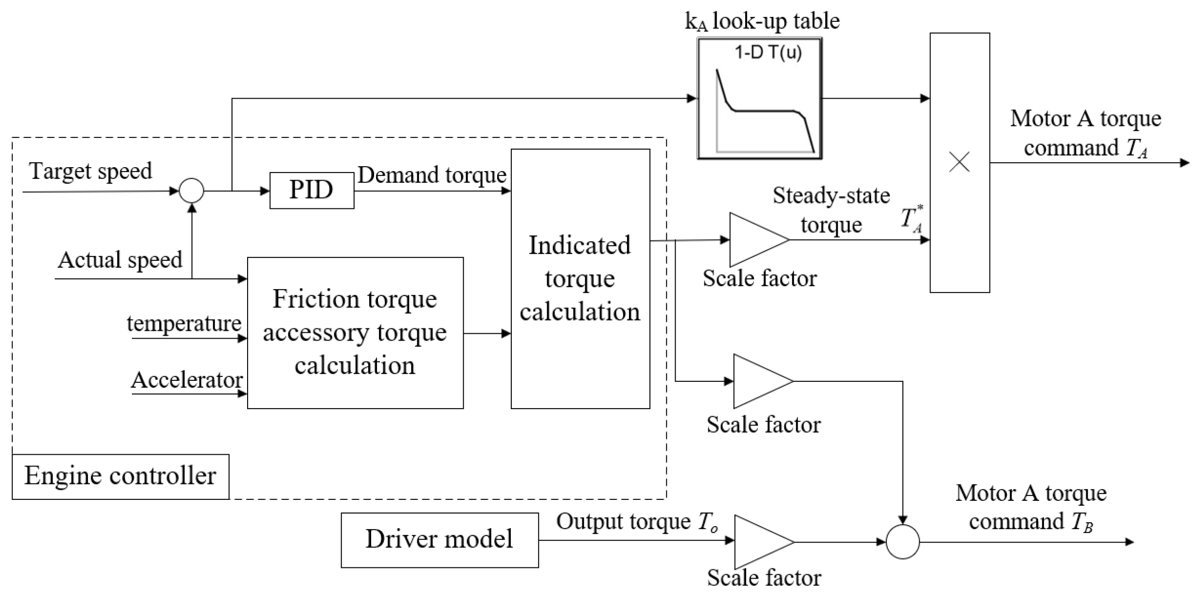
4. Engine Start-Up Coordination Control Strategy

The engine starting process in the process of traveling is divided into four phases: clutch speed regulation phase, clutch integration phase, engine anti-dragging phase, and engine speed regulation. For each stage of the vehicle dynamics model and characteristics, a corresponding coordinated control strategy was designed [12,14].

4.1. Clutch Speed Regulation Phase

In the pure electric driving process, the planetary row k 3 is in working condition and the planetary rows k 1 and k 2 are in idle state. As the vehicle speed changes, the input end of the coupling mechanism, that is, the passive end of the main clutch CL0, also generates idle speed; while the engine is in a stationary state at this time, the main clutch and the passive end of the main clutch CL0 generate a speed difference. If the differential clutch CL0 is not eliminated due to the speed difference, a large impact is inevitable. Therefore, before the engine is started, the clutch speed regulation needs to be performed. When the system enters the engine start mode, the clutch speed is firstly controlled. Unlike traditional engines that are driven by a starter motor, the hybrid system studied adjusts the motor speed to enable the engine to start smoothly and operate in a high-efficiency region. The main purpose of this stage is to use motor A to eliminate the main clutch speed difference, that is, to reduce the idle speed of the input of the coupling mechanism, reducing the impact of the main clutch CL0 engagement. At this stage, the master clutch CL0 is in the disengaged state and the brake B1 is engaged, which is same as that in the pure electric driving mode. According to the rotational speed coupling equation in EVT1 mode, if ω i = 0 , the target speed of motor A at this stage can be obtained:
ω A * = 1 + k 1 + k 2 1 + k 3 k 1 k 2 ω o
Using PID to control the torque of motor A, T A is obtained from Equation (6):
T A = k A p ω A ω A * + k A i 0 t ω A ω A * d t + k A d d ω A ω A * d t
During the process of adjusting the speed of motor A, the torque of motor A will interfere with the output torque due to the effect of the torque coupling. The coupling relationship between the output torque and the torque of motor A and motor B is as follows:
T o = 1 + k 1 + k 2 1 + k 3 k 1 k 2 T A + 1 + k 3 T B
Therefore, the torques of motor A and motor B need to be coordinated with each other at this stage to meet the demand of the driver for the output torque. The motor torque control algorithm is shown in Figure 2.

4.2. Clutch Engagement Phase

Because there is a clutch timing stage, the main clutch CL0 can achieve low-speed differential engagement, and the impact degree and the sliding work of the engagement process can be guaranteed. In actual control, set the logic threshold value of the clutch engagement command (this article takes Δ ω = 50 r/min). The selection of the logic threshold value cannot be too small, and the joint conditions are too strict or too large. If the clutch speed difference is too large, a shock is generated. When the clutch speed difference is lower than the logic threshold, the controller sends an engagement command. After a brief synchronization process, the clutch is quickly engaged and the system enters the engine start control phase.

4.3. Anti-Drag Phase of the Engine

The main purpose of this stage is to drag motor A and motor B so that the crankshaft speed of the engine reaches a firing speed from a standstill, and at the same time, the output torque in this process must be stable. The indicator for evaluating the output torque stability is the definition of impact degree. It is defined as follows:
j = d 2 V d t 2 = R i 0 d ω ˙ o d t
In the formula, j is the longitudinal impact of the vehicle, the impact of the German standard j ≤ 10 m/s3, and the Chinese standard j ≤ 17.64 m/s3 [15].
From Equation (8), if the output shaft speed ω o can maintain a linear change, i.e., the vehicle acceleration is kept constant, the vehicle impact can theoretically be maintained at zero. Therefore, if the trajectory of the output shaft is set and the control is applied to trajectory tracking, the problem of smoothness control in the engine-starting process can be converted into a speed-tracking control problem.
The tracker problem is one of linear quadratic optimal control problems [16]. The optimal control problem is divided into state regulator and tracker problems. The task of the state regulator is to consume as little energy as possible to maintain the system state in equilibrium. The state of the tracker is controlled so that the output closely follows a desired state trajectory without consuming excessive control energy. According to the dynamic model obtained by Equation (4), the input shaft speed and output shaft speed are selected as the state variables of the system. The torques of motor A and motor B are the control variables of the system, i.e.,
X = x 1 x 2 T = ω i ω o T U = u 1 u 2 T = T A T B T
The state space model of the coupling mechanism at this stage is
X ˙ = A X + B U + Γ Y = C X
where
A = 0 0 0 0 B = 1 b 11 b 22 b 21 b 12 a 11 b 22 a 12 b 12 a 22 b 12 a 12 b 11 a 11 b 21 a 22 b 11 C = 1 0 0 1 Γ = 1 b 11 b 22 b 21 b 12 b 12 T o b 11 T o
Since the rank of the matrix [ B A B ] is 2, the system is fully controllable; since the rank of the matrix [ C C A ] T is 2, the system is fully observable.
Set the trace of the state variable as
z t = z 1 t z 2 t = β i t ω o t 0 + β o t
where β i is the engine crankshaft angular acceleration; ω o ( t 0 ) is the initial speed of the output of the coupling mechanism at this stage; and β o is the angular acceleration of the output of the coupling mechanism. Under the premise of rigid assumptions, the relationship between β o and the longitudinal acceleration of the vehicle is as follows:
β o = i o R d V d t
In the target tracking trajectory z ( t ) , it is set that the crankshaft end rotation speed of the engine and the output speed of the coupling mechanism change in a linear manner; that is, the angular acceleration at the input and output ends is kept constant.
At the same time, the definition of the tracking error vector e ( t ) is
e t = z t Y t
Define the tracker performance functional as follows:
J = 1 2 t 0 t f e T Q e + u T R u d t + 1 2 e T t f Q 0 e t f
where,
Q = q 1 0 0 q 2 R = r 1 0 0 r 2 Q 0 = q 10 0 0 q 20
q 1 and q 2 represent the importance of the tracking error of the input speed and the output speed; r 1 and r 2 represent the importance of the control cost in the dynamic process; q 10 and q 20 represent the importance of the terminal tracking error.
In summary, the tracker problem is designed as shown in Equation (14). The result involves the solution of the Riccati equation and the control vector g ( t ) . In addition to the same feedback control as the optimal regulator system, the optimal tracker system also adds a forced control term associated with g ( t ) . The optimal control variable U ( t ) is the torque of motor A and motor B, which can be obtained by solving the vector matrix P ( t ) and g ( t ) .
P ˙ t = P t A A T P t + P t B R 1 B T P t C T Q C g ˙ t = A B R 1 B T P t T g t C T Q z t

4.4. Engine Active Speed Regulation Stage

After the engine reaches the firing speed, it generates the output torque and enters the engine’s active speed regulation stage. According to the engine’s unique characteristics, the fuel economy of the engine is roughly 1400 to 1700 r/min. Therefore, setting 1400 r/min is the target speed at this stage. In the EVT1 mode, there is a proportional relationship between motor A and the engine torque. According to the proportional relationship (15), the steady-state target torque of motor A can be calculated. Taking into account the coordinated control of motor A and the engine, this paper introduces a coordinated control coefficient k A , which is defined as the ratio of the actual torque of motor A in the stage of engine speed regulation to the steady-state target torque, as shown in Equation (16). In the steady-state condition, motor A is the load of the engine and k A = 1 . When the difference between the actual engine speed and the target engine speed is large, let k A take a negative value, that is, the motor A torque can play a role of assist; when the engine speed comes gradually close to its target speed, k A gradually approaches 1; that is, the torque of motor A also approaches the steady-state target torque. In the stage of engine speed regulation, the trajectory of the deviation of k A with engine speed is shown in Figure 3.
T * A = k 1 k 2 1 + k 1 1 + k 2 T e
k A = T A T * A
where T e is the engine torque; T * A is the steady-state target torque of motor A; k A is the coordination control parameter; and T A is the actual torque of motor A.
The motor A torque is coordinated by the torque coordination control coefficient, and the motor B torque needs to cooperate with the engine torque to meet the driver’s demand for the output torque. The relationship among the output torque T o , the engine torque and the motor B torque satisfies Equation (21). The engine torque is obtained from the engine command torque calculation module, and the output torque is obtained from the driver model, as shown in Figure 4. In summary, the coordinated torques of motor A and motor B can be separately calculated. Both are variables related to the engine operating point, which also embodies the characteristics of the stage of engine speed regulation.
T o = 1 + k 1 + k 2 1 + k 3 1 + k 1 1 + k 2 T e + 1 + k 3 T B

5. Ground Load Observer

For the optimal control problem of the engine’s anti-dragging stage, formula (10) needs to know the ground load, so a ground load observer is designed. According to (11), the system state-space equation is rewritten as follows:
x ˙ 1 x ˙ 2 = A 11 A 12 A 21 A 22 x 1 x 2 + B 1 B 2 u y = C 1 C 2 x 1 x 2
where
x 1 = T f x 2 = ω i ω o T u = T A T B T A 11 = 0 A 12 = 0 A 21 = 1 b 11 b 22 b 21 b 12 b 12 b 11 A 22 = 0 B 1 = 0 B 2 = 1 b 11 b 22 b 21 b 12 a 11 b 22 a 12 b 12 a 22 b 12 a 12 b 11 a 11 b 21 a 22 b 11 C 1 = 0 C 2 = I
According to Equation (18), the input shaft rotation speed and the output shaft rotation speed (state variable x 2 ) can be directly measured by the output variable y, and a state observer must be designed for the road load (state variable x 1 ). The state equation for the state variable x 1 is
x ˙ 1 = A 11 x 1 + A 12 y + B 1 u y ˙ = A 21 x 1 + A 22 y + B 2 u
if
v = A 12 y + B 1 u w = y ˙ A 22 y B 2 u
then
x ˙ 1 = A 11 x 1 + v w = A 21 x 1
The observer is designed for the subsystem (26), which is the original system’s dimensionality reduction state observer. Introducing the feedback matrix L, according to observer theory, the observer state equation for the subsystem (26) is
x ^ ˙ 1 = A 11 L A 21 x ^ 1 + ν + L w w = A 21 x ^ 1
where the value of the feedback matrix L is L = [ l 1 l 2 ] , where l 1 and l 2 are design parameters. According to (26) and (27), the dynamic equation of observer error is
T ˙ f T ^ ˙ f = A 11 L A 21 T f T ^ f = b 12 l 1 b 11 l 2 b 11 b 22 b 21 b 12 T f T ^ f
Therefore, the solution to the observation error is
T f T f c 0 e b 11 l 2 b 12 l 1 b 11 b 22 b 21 b 12 t
where c 0 is a constant, and the stability condition of the system is b 11 l 2 b 12 l 1 b 11 b 22 b 21 b 12 < 0 ; at this time, the observation error of the load torque gradually approaches zero with the time t in the form of an exponent, and the approach speed is related with the pole arrangement position.
Because a derivative of the output variable y in the variable w is introduced in Equation (25), which increases the system’s sensitivity to noise, a new state variable z is defined:
z = x 1 L y
Substituting it into Equation (28) results in
z ˙ = A 11 L A 21 z + B 1 L B 2 u + A 12 L A 22 + A 11 L A 21 L y x 1 = z + L y
The estimated value x 1 of the state variable x 1 can be obtained by Equation (31).
Figure 5 shows the structural block diagram of the designed road load observer. The observer model takes the output variables and control variables of the state equation of the motive power transmission system as input, and the observed value of the road load T f is obtained through the introduced state variable z.
The ground load observer simulation results are shown in Figure 6.

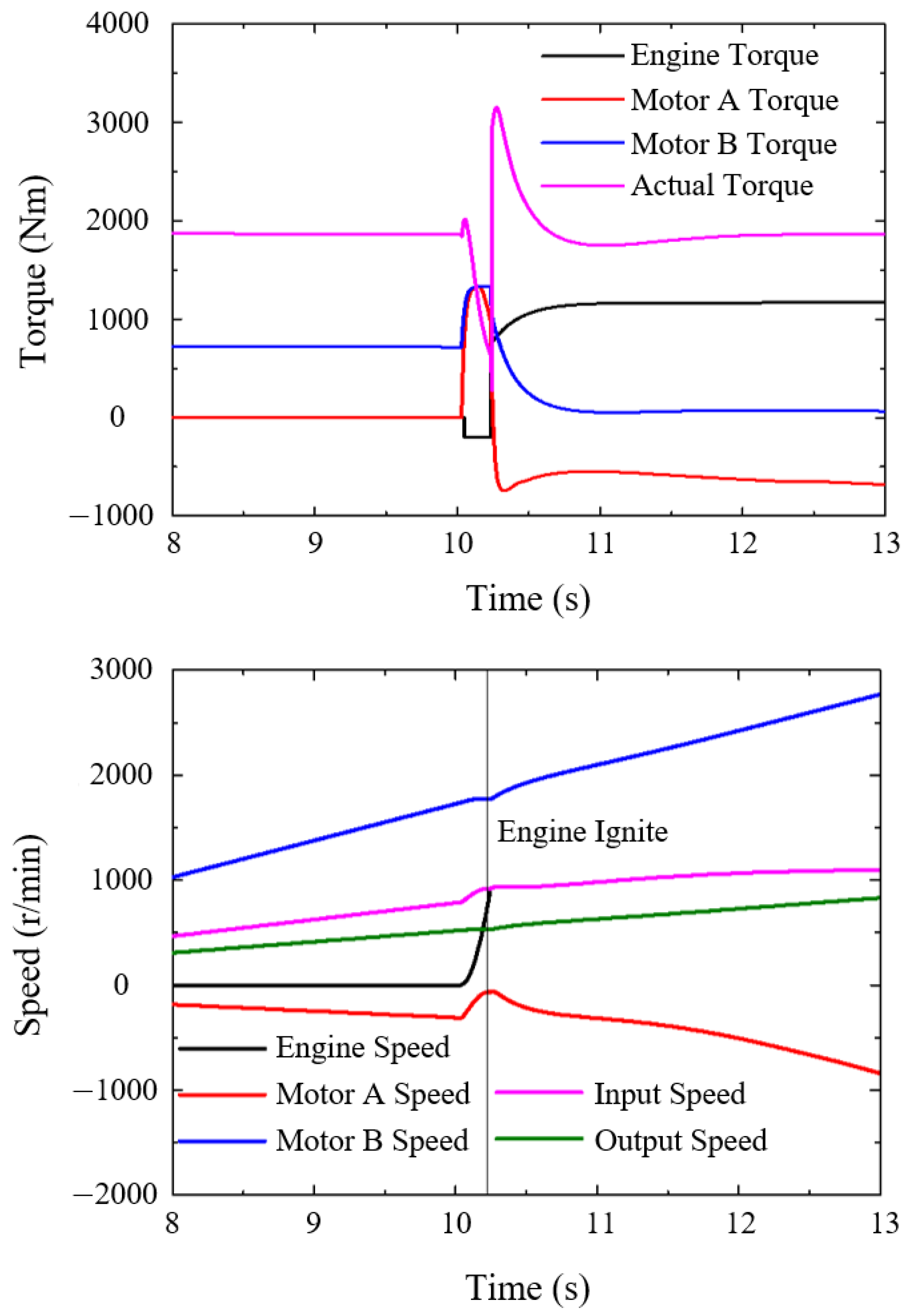
6. Control Strategy Simulation Verification
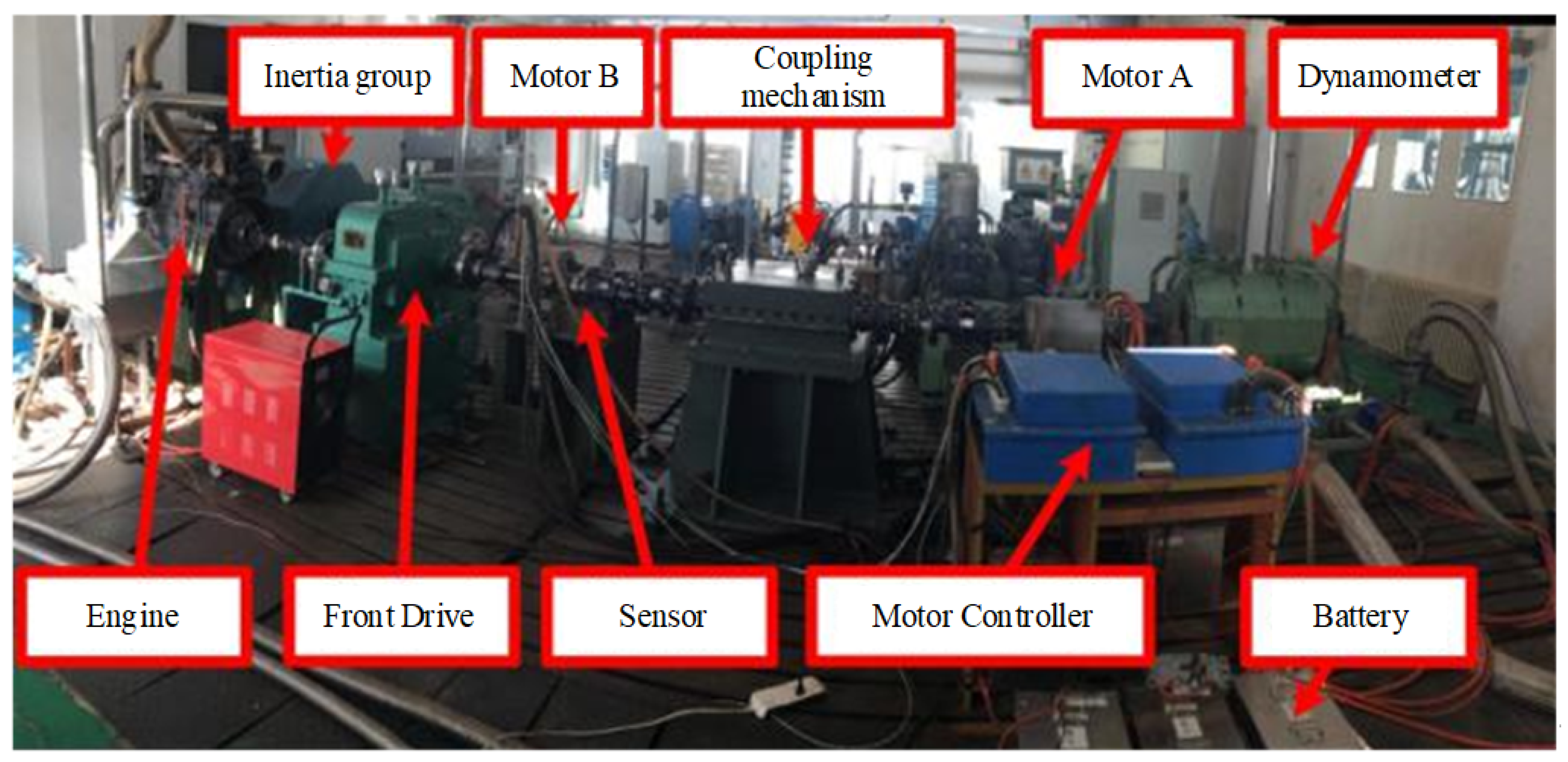
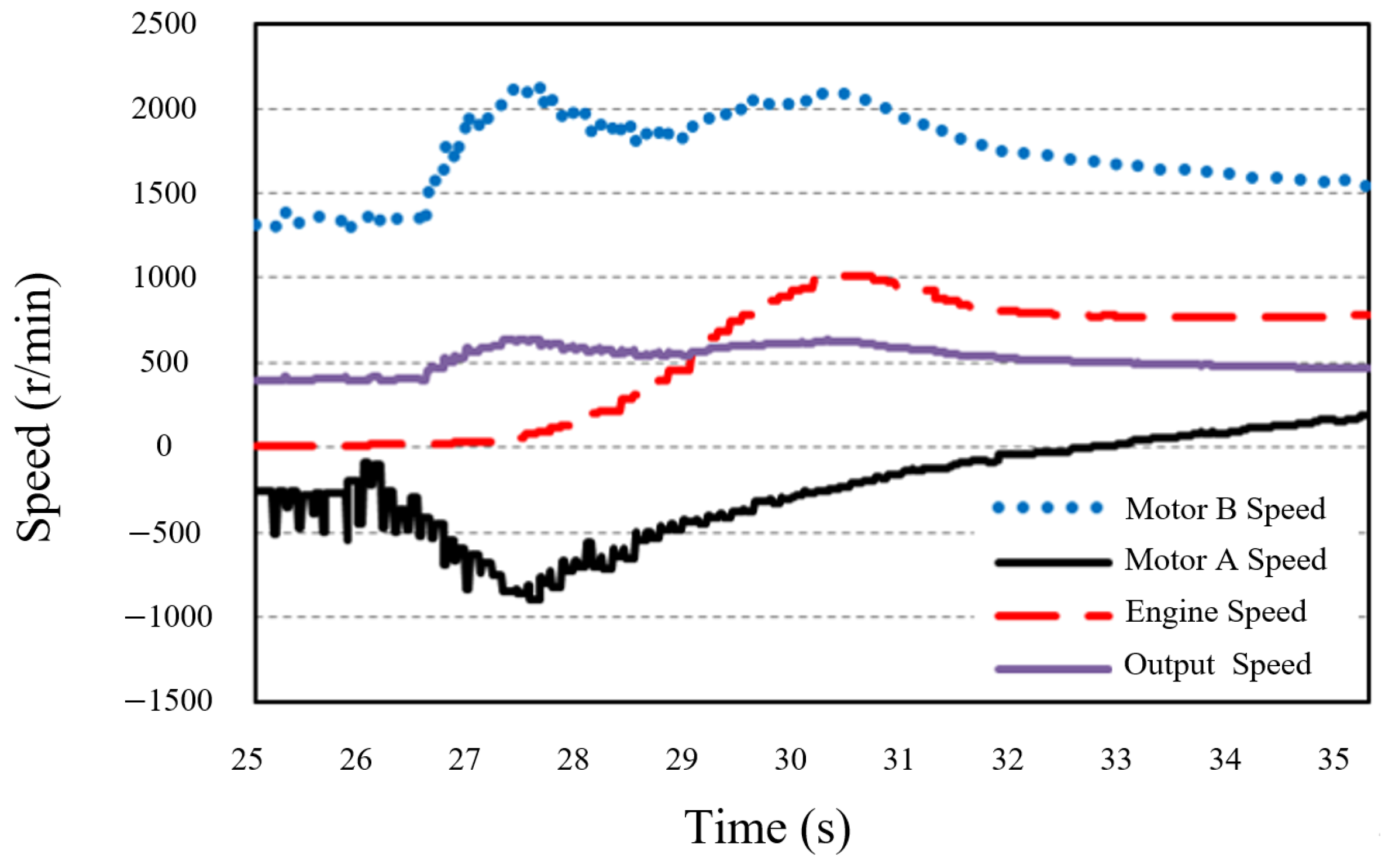
Figure 7 shows the simulation results of the engine starting process when the system does not use coordinated control. Before the engine starts, the vehicle is in pure electric drive mode. At 10 s, the engine receives the start signal; then, the main clutch CL0 starts to adjust speed and engage. It can be seen from the simulation results that the actual output torque drops rapidly in the system, which is due to the intervention of the engine as a load during the start-up process. At 10.4 s, the engine ignites, the actual output torque of the system suddenly increases, and the system also switches to the hybrid drive mode. After that, due to the torque adjustment of motor A and motor B, the actual output torque of the system is gradually restored, and the system is stable to the hybrid drive mode. The entire starting process has a torque fluctuation of 2000 Nm, and the maximum impact of the vehicle reaches 30 m/s3, far exceeding the standard of 10 m/s3.
The simulation result after adopting the multi-stage coordinated control strategy is shown in Figure 8. The simulation condition is set as the engine start speed V = 8 km/h, and the output torque is kept above and below 1900 Nm during the start-up process. As can be seen from the figure, the engine start-up process lasts for 3.5 s from 9.1 s to 12.6 s, and the engine anti-dragging phase takes 1.0 s. The moments of high impact are four key points: clutch start speed, clutch engagement, engine ignition, and engine start-up process. In the multi-stage coordinated control strategy, the maximum impact does not exceed 2.5 m/s3. This advantage is attributed to the strategic conversion of the stability control challenge within the engine start-up phase into a rotational speed tracking control issue, guaranteeing a consistent output torque and diminishing the impact severity.

7. Bench Test

In order to verify the coordinated control strategy of hybrid vehicle engine start, a system test bench was built, as shown in Figure 9. The test bench connection diagram is shown in Figure 10. A full-vehicle controller built with Rapid ECU rapid prototyping was used to calibrate and record test data online using Meca version 1.98 software.
The result of the bench test of the engine starting during the vehicle traveling is shown in Figure 11. First of all, the vehicle works in pure electric drive mode, motor B drive. At 26.4 s, the engine received the start command and entered the engine start mode. Motor A and motor B are driven together and drag the engine speed to idle, so that the engine was ignited. The idle speed regulation mode was reached, and the engine speed stabilized to 800 rpm finally. The entire engine start process lasts for about 5.4 s. During the start-up process, the brake B1 is always engaged. The speed of motor B fluctuates about 600 r/min, and the output shaft speed fluctuates up and down by about 180 r/min. The system speed has little impact.

8. Conclusions

This paper delves into the complexity of the starting process of hybrid electric vehicles and categorizes it into four phases. By designing a coordinated control strategy, the engine anti-drag start problem is transformed into an optimal speed-tracking problem, achieving a smooth transition from pure electric mode to hybrid driving mode. Moreover, to ensure the stability of the engine start and reduce the impact during driving, this paper develops a reduced-order load observer that can monitor ground load information in real time, providing crucial support for the coordinated control strategy. Through simulation and bench testing, the effectiveness of the proposed engine start coordinated control strategy is validated. Compared to the non-coordinated control strategy, the strategy designed in this paper significantly reduces the maximum impact on the vehicle during engine start-up from 30 to below 2.5 m/s3. These results indicate that the proposed coordinated control strategy not only optimizes the starting performance of hybrid electric vehicles but also enhances ride comfort and driving smoothness. Therefore, this study offers new insights and methods for the control of power-train systems in hybrid electric vehicles, holding significant reference value for the advancement and application of hybrid technology. In subsequent research endeavors, we intend to delve more profoundly into the efficiency considerations associated with the start-up process with the objective of refining the overall performance of hybrid electric vehicles.

Author Contributions

Methodology, N.Y.; Software, X.Z.; Validation, N.Y.; Formal analysis, L.H.; Resources, L.H.; Data curation, L.H.; Writing—original draft, X.Z.; Writing—review & editing, N.Y. All authors have read and agreed to the published version of the manuscript.

Funding

This research received no external funding.

Data Availability Statement

The raw data supporting the conclusions of this article will be made available by the authors on request.

Conflicts of Interest

The authors declare no conflicts of interest.

References

  1. Zhao, Z. Mode Transition Control for Four Wheel Drive Hybrid Electric Car. J. Mech. Eng. 2011, 47, 100. [Google Scholar]
  2. Ni, C.; Zhang, Y.; Zhao, Q.; Boukehili, A. Dynamic Torque Control Strategy of Engine Clutch in Hybrid Electric Vehicle. J. Mech. Eng. 2013, 49, 114–121. [Google Scholar]
  3. Li, L.; Li, X.; Lu, H.; Deng, J. A study on the motor cranking strategy and start performance of a HEV engine. Automot. Eng. 2016, 38, 133–140. [Google Scholar]
  4. Zhang, N.; Zhao, F.; Luo, Y. A Dynamic Coordinated Control Strategy for Mode-Switch of Hybrid Electric Vehicle Based on the Effect Control. In Proceedings of the FISITA World Automotive Congress; Springer: Berlin/Heidelberg, Germany, 2013. [Google Scholar]
  5. Luo, Y.; Wang, Z. Mode Switching Coordination Control of Electromechanical Continuously Variable Transmission Hybrid Drive System. Automot. Eng. 2015, 5, 526–532. [Google Scholar]
  6. Yonggang, L.; Datong, Q.; Zhenjun, L.; Yang, Y. Research on Engine Starting Control Strategy for Single-motor Heavy Hybrid Power System during Running. Automot. Eng. 2015, 37, 49–54. [Google Scholar]
  7. Yan, X.; Zhong, Y.; Zhong, Z. Research on Optimal Control of Power Smoothing Switching in HEV Transmission System. Automot. Eng. 2008, 30, 309–311. [Google Scholar]
  8. Qin, D.; Shang, Y.; Yang, G. Smoothness control of start-up engine during pure electric traveling of plug-in hybrid vehicle. J. Chongqing Univ. 2015, 4, 1–9. [Google Scholar]
  9. Zhu, F.; Chen, L.; Yin, C.; Shu, J. Dynamic modelling and systematic control during the mode transition for a multi-mode hybrid electric vehicle. Proc. Inst. Mech. Eng. Part D J. Automob. Eng. 2013, 227, 1007–1023. [Google Scholar]
  10. Kim, H.; Kim, J.; Lee, H. Mode Transition Control Using Disturbance Compensation for a Parallel Hybrid Electric Vehicle. Proc. Inst. Mech. Eng. Part D J. Automob. Eng. 2011, 225, 150–166. [Google Scholar]
  11. Kim, S.; Park, J.; Hong, J.; Lee, M.; Sim, H. Transient Control Strategy of Hybrid Electric Vehicle during Mode Change. In Proceedings of the SAE 2009 World Congress; SAE: Warrendale, PA, USA, 2009. [Google Scholar]
  12. Canova, M.; Guezennec, Y.; Yurkovich, S. On the Control of Engine Start/Stop Dynamics in a Hybrid Electric Vehicle. J. Dyn. Syst. Meas. Control 2009, 131, 636–650. [Google Scholar]
  13. Li, J.; Wei, H. Coordinated Control of Downshift Powertrain of Combined Clutch Transmissions for Electric Vehicles. Math. Probl. Eng. 2014, 2014, 643762. [Google Scholar]
  14. Cui, T.; Yan, Y. Harmonized Switching Control of Parallel Hybrid Electric Vehicle from Pure Electric Motor to Engine Driven. J. Highw. Transp. Res. Dev. 2014, 31, 153–158. [Google Scholar]
  15. Zhao, Z.; Hu, X.; Jiang, J. Sliding Mode Variable Structure Coordinated Control and Real-time Optimization for Starting Dual Clutch Transmission. J. Mech. Eng. 2012, 48, 87–105. [Google Scholar]
  16. Liu, B. Modern Control Theory, 2nd ed.; Mechanical Industry Press: South Norwalk, CT, USA, 2006. [Google Scholar]
Figure 1. Power split hybrid system structure diagram.
Electronics 13 03373 g001
Figure 2. Motor torque control algorithm in the phase of clutch speed regulation.
Electronics 13 03373 g002
Figure 3. Torque coordinated control coefficient of motor A.
Electronics 13 03373 g003
Figure 4. Coordinated control strategy for active speed regulation of engine.
Electronics 13 03373 g004
Figure 5. Ground load observer block diagram.
Electronics 13 03373 g005
Figure 6. Ground load observer simulation results.
Electronics 13 03373 g006
Figure 7. Engine starting process without coordinated control strategy.
Electronics 13 03373 g007aElectronics 13 03373 g007b
Figure 8. Engine starting process using a multi-stage coordinated control strategy.
Electronics 13 03373 g008aElectronics 13 03373 g008b
Figure 9. Hybrid system test bench.
Electronics 13 03373 g009
Figure 10. Hybrid system test bench connection diagram.
Electronics 13 03373 g010
Figure 11. Bench test results.
Electronics 13 03373 g011
Table 1. Parameters of the hybrid system.
NameValue
Vehicle mass40,000 kg
Maximum engine power1103 kW
Maximum engine speed4200 r/min
Battery capacity60 Ah
Battery charging and discharging power180 kW
Maximum motor power370 kW
Maximum motor speed6000 r/min
Table 2. Drive mode and control element state.
Driving ModeMain Clutch CL0Clutch CL1Brake B1
Pure electric driveseparateseparateengage
Pure mechanical driveengageengageengage
EVT1engageseparateengage
EVT2engageengageseparate
Disclaimer/Publisher’s Note: The statements, opinions and data contained in all publications are solely those of the individual author(s) and contributor(s) and not of MDPI and/or the editor(s). MDPI and/or the editor(s) disclaim responsibility for any injury to people or property resulting from any ideas, methods, instructions or products referred to in the content.

