Article

Model Assisted Extended State Observer-Based Deadbeat Predictive Current Control for Modular Multilevel Converter

Chengdu Aircraft Industrial (Group) Co., Ltd., Chengdu 610092, China
*
Author to whom correspondence should be addressed.
Electronics 2024, 13(19), 3789; https://doi.org/10.3390/electronics13193789
Submission received: 2 August 2024 / Revised: 5 September 2024 / Accepted: 11 September 2024 / Published: 24 September 2024

Abstract

:
Aiming at the issues of control delay and circuit parameter mismatch in three-phase modular multilevel converters (MMCs), this paper proposes a model assisted extended state observer-based deadbeat predictive current control (MAESO-based DPCC) strategy to regulate the AC-side current and internal circulating current. The model assisted ESO (MAESO) is employed to estimate the predicted values of the d- and q-axis components of the AC-side current, the internal circulating current, and system disturbance caused by the other certain and uncertain factors (including circuit parameter changes) of MMC at the time instant k + 1, and the required control input at the time instant k + 1 is then calculated based on the deadbeat control principle. The proposed control strategy not only maintains excellent steady-state performance and fast dynamic response characteristics similar to those of the traditional deadbeat predictive current control (DPCC) strategy but also has stronger robustness in the case of circuit parameter changes. The proposed control strategy was ultimately compared with the traditional DPCC strategy via experiments, and the experimental results verify the feasibility and effectiveness of the proposed control strategy.

1. Introduction

With the advantages of low switching frequency, good output waveform quality, complete modularity, easy scalability, and flexible control, modular multilevel converters (MMCs) have received widespread attention in many electrified transportation fields, such as electric traction drives, aviation power systems, electric ship, and electrified railways [1,2,3,4,5,6,7]. However, the special modular structure of MMCs determines that they not only need to control the AC-side current but also need to consider the internal circulating current suppression and the balance of submodule (SM) capacitor voltages during normal operation [3,5,6,8], making the control algorithm of MMCs particularly complex. To date, there has been extensive research on the control of MMCs, among which control strategies based on proportional integration (PI) and proportional resonance (PR) controllers are the most representative [6,8,9,10,11,12,13,14,15,16]. Although these types of control strategies can achieve all the control objectives of MMCs, the control performance heavily depends on the selection of control parameters, and the design and tuning of PI (PR) control parameters is a comprehensive and interdependent process. The actual control performance may be greatly affected by suboptimal parameters, leading to a slow dynamic response [9,10,12,14,17,18].
To avoid complex control parameter tuning processes and improve system dynamic response performance, some researchers have introduced the idea of deadbeat control into the control of MMCs [11,12,13,14,15,16,19]. By means of the forward difference method and nearest level approximation, ref. [11] predicted the optimal switching state in reverse based on the current reference value and the average capacitance voltage of each bridge arm SM. In this way, control of the AC-side current and circulating current was achieved. However, the algorithm did not consider the impact of control delay in actual control systems. In actual digital control systems, due to the inability to instantaneously complete sampling, control algorithm calculations, and control output, the control output calculated at time instant k is only effective at time instant k + 1, which means that a delay of one control cycle occurs. Without delay compensation, deadbeat control may result in inaccurate or even unstable system control [12,20]. In refs. [13,14,15], the reference values of the circulating current and AC-side current were taken as inputs for deadbeat control. Then, the optimal reference voltage values of the upper and lower bridge arms based on the discrete state equations of the system were obtained to achieve control of the AC-side current and circulating current. However, these algorithms also do not consider the influence of control delay in actual digital control systems. In [16], a deadbeat current control strategy (DPCC) was proposed in the dq coordinate system while considering the control delay, and this strategy can achieve rapid adjustment of the AC-side current. However, this study did not explore deadbeat control for circulating current suppression.
In addition, the abovementioned deadbeat control strategies all focus on improving the system’s dynamic response performance without considering the impact of circuit parameter perturbations on the control performance. In fact, during the operation of MMCs, due to measurement errors, the external environment, operating conditions, component aging, and losses, circuit parameter perturbations are inevitable [13]. Circuit parameter perturbations can affect the control performance of deadbeat control, leading to inaccurate tracking of reference values and even system instability [13]. To avoid this issue, a DPCC algorithm considering delay compensation for MMCs was proposed to improve the system dynamic response speed [13]. Moreover, the impacts of mismatched AC-side inductance and arm inductance parameters on the prediction error at time instant k + 1 and the stability of the control system have been analyzed. On this basis, a method for the online estimation of inductance parameters was introduced, which can effectively reduce the impact of inductance changes on the system and enhance the robustness of the control system. However, this algorithm only considers the changes in inductance parameters, and changes in the arm resistance and AC-side resistance can also have adverse effects on the control performance. Therefore, it is necessary to research a robust current control strategy for MMCs that can simultaneously adapt to changes in the inductance and resistance parameters. Extended state observer (ESO) is a nonlinear observer that can observe system disturbances. It was proposed by Prof. Han Jingqing in the 1990s and is an important component of active disturbance rejection control technology. ESO does not rely on precise mathematical models of the system, nor does it require direct measurement to accurately estimate the unknown and uncertain parts of the system [21,22,23,24]. In recent years, in research on PWM rectifiers [25] and permanent magnet synchronous motors [26,27], relevant scholars have combined ESO and deadbeat control to study deadbeat predictive control strategies based on ESO to ensure system dynamic performance while enhancing system robustness. However, this idea has rarely been reported in the research on MMC control, and its effectiveness in MMC control also needs further analysis and verification.
In light of the situations mentioned above, this paper comprehensively considers the problems of control delay and circuit parameter mismatch and proposes a deadbeat predictive current control strategy based on model-assisted ESO (MAESO-based DPCC) to simultaneously regulate the AC-side current and internal circulating current in MMCs. The proposed control strategy estimates values for the AC-side current’s d- and q-axis components, internal circulating current, and system disturbances caused by other deterministic and uncertain factors (including circuit parameter changes) at time instant k + 1 through an MAESO. Then, based on the deadbeat control principle, the required control output at time instant k + 1 is calculated. The proposed control strategy not only maintains the superior steady-state performance and fast dynamic response characteristics of the traditional DPCC strategy but also has stronger robustness under changes in circuit parameters. Finally, the proposed control strategy was compared and analyzed with the traditional DPCC strategy by experimentation, and the experimental results verified the feasibility and effectiveness of the proposed control strategy.

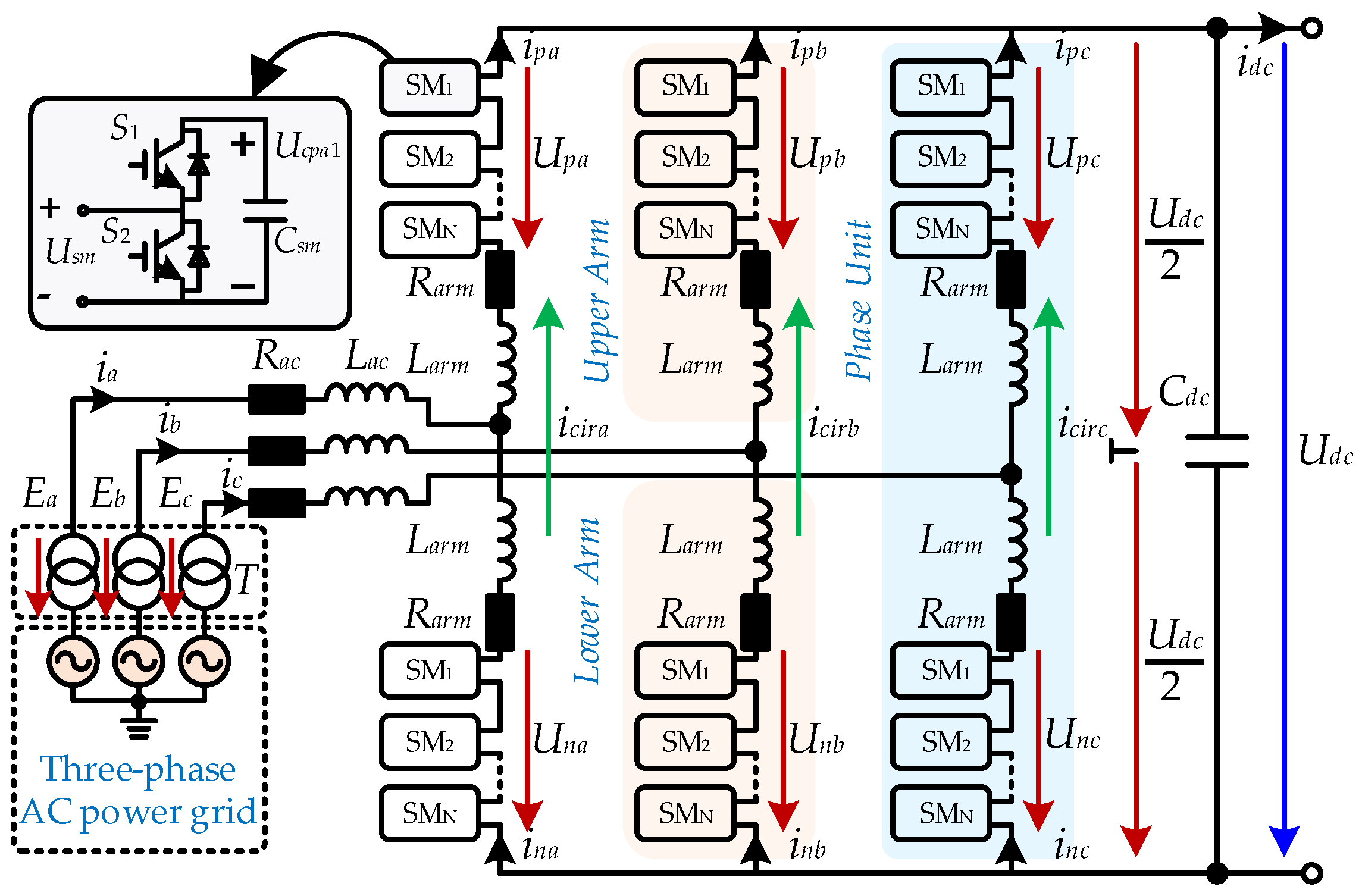
2. Topology Structure and Mathematical Model of MMC

2.1. Topology Structure

The topology of a three-phase MMC is shown in Figure 1. The MMC is connected to the three-phase AC power grid through the AC-side inductance Lac and resistance Rac, as well as the three-phase step-down transformer T. The MMC consists of three identical phase units and six bridge arms. Each bridge arm is composed of N half-bridge-type submodule SMs with the same structure, as well as a bridge arm inductance Larm and a bridge arm resistance Rarm cascaded together. The bridge arm inductance is used to suppress the internal circulating currents and limit the fault currents [5,6,8,9,10]. The SM consists of a half-bridge and a DC energy storage capacitor Csm, and its port output voltage Usm is determined by its operating state [6,7,8,9,10,11,12,13,17,18]. In addition, in Figure 1, Cdc is the DC-side support capacitor; Ej and ij are the voltage and input current of the AC power grid for phase j (j = a, b, c), respectively; Upj and Unj represent the voltage of the upper and lower bridge arms of phase j, respectively (p represents the upper bridge arm, while n represents the lower bridge arm); ipj and inj represent the upper and lower bridge arm currents of phase j, respectively; icirj represents the internal circulating current of phase j; Udc and idc represent the DC-side voltage and current, respectively; and UcpjN and UcnjN represent the voltage of the Nth submodule capacitor in the upper and lower bridge arms of phase j, respectively.

2.2. Mathematical Model

Due to the identical three-phase structure of the MMC, analyzing a mathematical model of the MMC using any phase as an example is sufficient [11]. According to the reference direction of the voltage and current shown in Figure 1 and based on the definition of the circulating current and Kirchhoff’s current law (KCL), the relationship between the circulating current, input current, and upper and lower bridge arm currents in phase j can be obtained [13,16]:
i j = i p j i n j
i c i r j = ( i p j + i n j ) / 2
According to Figure 1, based on Kirchhoff’s voltage law (KVL), the following circuit equation can be obtained:
E j = R a c i j + L a c d i j d t + L a r m d i p j d t + R a r m i p j U p j + U d c 2 E j = R a c i j + L a c d i j d t L a r m d i n j d t R a r m i n j + U n j U d c 2
The dynamic equations of the input current and circulating current can be further derived from Equations (1)–(3):
d i j d t = U p j ( 2 L a c + L a r m ) U n j ( 2 L a c + L a r m ) ( 2 R a c + R a r m ) ( 2 L a c + L a r m ) i j + 2 E j ( 2 L a c + L a r m ) d i c i r j d t = U p j 2 L a r m + U n j 2 L a r m R a r m L a r m i c i r j U d c 2 L a r m
The differential mode voltage Udiffj and common mode voltage Ucomj of the upper and lower bridge arms are defined as [13]:
U d i f f j = ( U n j U p j ) / 2
U c o m j = ( U n j + U p j ) / 2
The equivalent inductance Leq and equivalent resistance Req on the AC side of the MMC are defined as [9]:
L e q = L a c + 0.5 L a r m
R e q = R a c + 0.5 R a r m
By substituting Equations (5)–(8) into Equation (4), the following mathematical expressions for the dynamic characteristics of the AC and DC sides of the MMC can be obtained:
L e q d i j d t = E j R e q i j U d i f f j
L a r m d i c i r j d t = U c o m j R a r m i c i r j U d c 2
According to Equations (9) and (10), the equivalent circuits on the AC and DC side of the three-phase MMC can be obtained, as shown in Figure 2a,b, respectively. According to Figure 2, the AC-side current ij can be controlled by adjusting the differential mode voltage Udiffj, and the internal circulating current icirj can be controlled by adjusting the common mode voltage Ucomj.

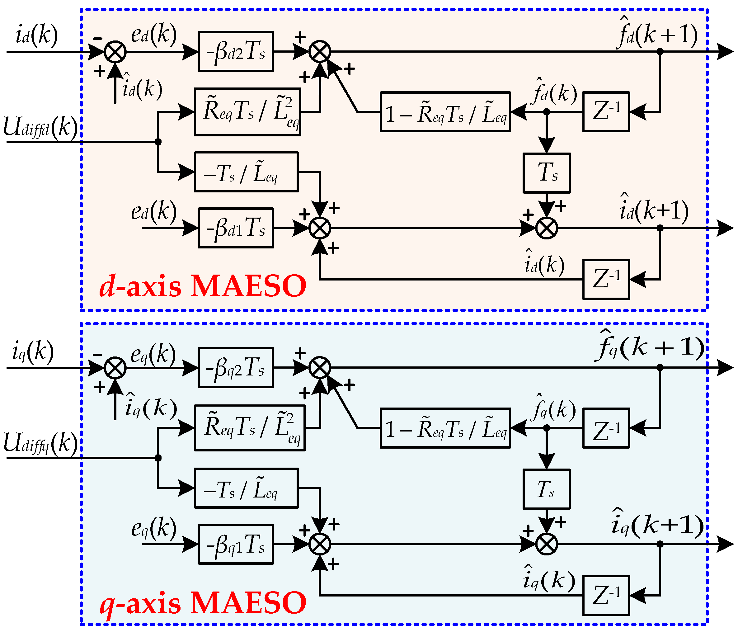
3. Proposed MAESO-Based DPCC Strategy

To improve the dynamic response performance of the system while enhancing the robustness to variations in circuit parameters (including inductance and resistance parameters), this section comprehensively considers the problems of control delay and model parameter mismatch. By combining the MAESO and the ideas of deadbeat predictive control, an MAESO-based DPCC strategy is proposed to regulate the AC-side current and internal circulating current of the MMC. The specific details are as follows.

3.1. Principle of MAESO

Linear ESOs encompass various forms, such as object model-free ESOs and MAESOs [24]. Compared to the object model-free ESO, the MAESO can improve the estimation accuracy of the disturbances without reducing bandwidth since part of the information of the object is obtained and integrated into the ESO. Taking a first-order single-input–single-output system with disturbances as an example, the specific implementation of the MAESO is shown below:
x ˙ 1 = a x 1 + w + b u y = x 1
where u and y represent the output and input of the system, respectively; w is the unknown disturbance of the system; b is the control input coefficient; and a is known. Considering f = a x 1 + w is the system total disturbance and expanding it as a new system state variable x 2 , that is, x 2 = f = a x 1 + w , the original system (11) can be expressed as:
x ˙ 1 = x 2 + b u x ˙ 2 = a x ˙ 1 + w ˙ = a x 2 + a b u + w ˙ y = x 1
where w ˙ represents the differential of the unknown disturbance w in the system.
According to Equation (12), the MAESO can be designed as follows [24]:
e 1 = x 1 x ^ 1 x ^ ˙ 1 = x ^ 2 + b u + β 1 e 1 x ^ ˙ 2 = a x ^ 2 + a b u + β 2 e 1
where e 1 is the estimation error of output variable x 1 ; x ^ 1 is the estimated value of system output x 1 ; x ^ 2 is the estimated system total disturbance f; and β 1 , β 2 are the observer gains of the MAESO. By selecting appropriate values for β 1 , β 2 , the MAESO can achieve accurate estimation of the state variables in (12). The determination of β 1 , β 2 can be achieved based on the concept of observer bandwidth in refs. [23,24], namely:
β 1 = 2 ω 0 + a β 2 = ω 0 2 + 2 ω 0 a + a 2
where ω 0 is the bandwidth of the observer.

3.2. AC-Side Current Control

By applying the Park transform to Equation (9), the mathematical model of the MMC’s AC side in the dq synchronous rotating coordinate system can be obtained as follows:
L e q d i d d t = E d R e q i d + ω L e q i q U d i f f d L e q d i q d t = E q R e q i q ω L e q i d U d i f f q
where Ed and Eq are the d-axis and q-axis components of the MMC’s AC-side grid voltage Ej, respectively; id and iq are the d-axis and q-axis components of the MMC’s AC-side current ij, respectively; and Udiffd and Udiffq are the d-axis and q-axis components of the differential voltage Udiffj on the upper and lower bridge arms of the MMC, respectively.
Assuming that the AC-side inductance, AC-side resistance, bridge arm inductance, and bridge arm resistance in the control system are L ˜ a c , R ˜ a c , L ˜ a r m , and R ˜ a r m , respectively, and considering model parameter mismatch, the mathematical model of the AC side of the MMC described in Equation (15) in the dq synchronous rotating coordinate system can be rewritten as:
d i d d t = E d L ˜ e q R ˜ e q L ˜ e q i d + ω i q U d i f f d L ˜ e q + d d d i q d t = E q L ˜ e q R ˜ e q L ˜ e q i q ω i d U d i f f q L ˜ e q + d q L ˜ e q = L ˜ a c + 0.5 L ˜ a r m = L a c + Δ L a c + 0.5 ( L a r m + Δ L a r m ) R ˜ e q = R ˜ a c + 0.5 R ˜ a r m = R a c + Δ R a c + 0.5 ( R a r m + Δ R a r m )
where Δ R a c , Δ L a c , Δ R a r m , and Δ L a r m are the deviations between the actual values of the circuit parameters and the values used in the control system; dd and dq represent the disturbances imposed on the d-axis and q-axis subsystems due to the mismatched circuit parameters, respectively, which are as follows:
d d = Δ L e q E d L ˜ e q ( L ˜ e q Δ L e q ) + R ˜ e q Δ L e q + L ˜ e q Δ R e q L ˜ e q ( L ˜ e q Δ L e q ) i d Δ L e q U d i f f d L ˜ e q ( L ˜ e q Δ L e q ) d q = Δ L e q E q L ˜ e q ( L ˜ e q Δ L e q ) + R ˜ e q Δ L e q + L ˜ e q Δ R e q L ˜ e q ( L ˜ e q Δ L e q ) i q Δ L e q U d i f f q L ˜ e q ( L ˜ e q Δ L e q )
where Δ L e q is the deviation between L e q and L ˜ e q .
According to the design concept of the aforementioned MAESO, the d- and q-axis components Udiffd and Udiffq of the differential voltage Udiffj on the upper and lower bridge arms of the MMC in Equation (16) are considered as inputs for the d-axis and q-axis subsystems, respectively. The d-axis and q-axis components id and iq of the AC-side current are considered as the state variables and outputs of the d- and q-axis subsystems, respectively. E d / L ˜ e q + ω i q + d d = w d and E q / L ˜ e q ω i d + d q = w q are considered as the unknown disturbances of the d- and q-axis subsystems, respectively; R ˜ e q i d / L ˜ e q + w d and R ˜ e q i q / L ˜ e q + w q are the total disturbances of the d- and q-axis subsystems, respectively, which are represented by fd and fq, respectively. By expanding fd and fq to a new state variable corresponding to the subsystem, the following expression can be obtained to describe the d- and q-axis subsystems:
i ˙ d = f d 1 L ˜ e q U d i f f d f ˙ d = R ˜ e q L ˜ e q f d + R ˜ e q L ˜ e q 2 U d i f f d + w ˙ d y = i d
i ˙ q = f q 1 L ˜ e q U d i f f q f ˙ q = R ˜ e q L ˜ e q f q + R ˜ e q L ˜ e q 2 U d i f f q + w ˙ q y = i q
To observe id, iq, fd, and fq, according to Equations (18) and (19), the MAESO of the d-axis and q-axis subsystems can be designed as follows:
e d = i ^ d i d i ^ ˙ d = f ^ d 1 L ˜ e q U d i f f d β d 1 e d f ^ ˙ d = R ˜ e q L ˜ e q f ^ d + R ˜ e q L ˜ e q 2 U d i f f d β d 2 e d
e q = i ^ q i q i ^ ˙ q = f ^ q 1 L ˜ e q U d i f f q β q 1 e q f ^ ˙ q = R ˜ e q L ˜ e q f ^ q + R ˜ e q L ˜ e q 2 U d i f f q β q 2 e q
where ed and eq are the estimation errors of the d-axis current id and q-axis iq, respectively; i ^ d and f ^ d are the estimated values of the d-axis current id and disturbance fd; i ^ q and f ^ q are the estimated values of the q-axis current iq and disturbance fq, respectively; β d 1 and β d 2 are the gains of the d-axis subsystem MAESO; and β q 1 and β q 2 are the gains of the q-axis subsystem MAESO.
To facilitate the implementation of the MAESO in digital controllers, the first-order forward difference method is used to discretize Equations (20) and (21), and the discrete forms of the designed ESO for the d-axis and q-axis subsystems can be obtained:
e d ( k ) = i ^ d ( k ) i d ( k ) i ^ d ( k + 1 ) = i ^ d ( k ) + T s f ^ d ( k ) 1 L ˜ e q T s U d i f f d ( k ) β d 1 T s e d ( k ) f ^ d ( k + 1 ) = ( 1 R ˜ e q L ˜ e q T s ) f ^ d ( k ) + R ˜ e q L ˜ e q 2 T s U d i f f d ( k ) β d 2 T s e d ( k )
e q ( k ) = i ^ q ( k ) i q ( k ) i ^ q ( k + 1 ) = i ^ q ( k ) + T s f ^ q ( k ) 1 L ˜ e q T s U d i f f q ( k ) β q 1 T s e q ( k ) f ^ q ( k + 1 ) = ( 1 R ˜ e q L ˜ e q T s ) f ^ q ( k ) + R ˜ e q L ˜ e q 2 T s U d i f f q ( k ) β q 2 T s e q ( k )
where e d ( k ) and e q ( k ) represent the estimation errors of the d-axis current id and q-axis current iq at time instant k, respectively; i ^ d ( k ) and f ^ d ( k ) are the estimated values for the d-axis current id and disturbance fd at time instant k, respectively; i ^ d ( k + 1 ) and f ^ d ( k + 1 ) are the estimated values for the d-axis current id and disturbance fd at time instant k + 1, respectively; i ^ q ( k ) and f ^ q ( k ) are the estimated values for the q-axis current iq and disturbance fq at time instant k, respectively; and i ^ q ( k + 1 ) and f ^ q ( k + 1 ) are the estimated values for the q-axis current iq and disturbance fq at time instant k + 1, respectively.
According to Equations (22) and (23), a structural diagram of the discrete form of the MAESO for the d-axis and q-axis subsystems can be obtained, as shown in Figure 3. When the observer is stable, the state variables of the d-axis and q-axis subsystems can be accurately estimated. Therefore, the required d-axis and q-axis currents and system disturbances in the control system can be replaced by estimated values from the MAESO. According to the basic principle of deadbeat control and considering the need to compensate for the delay of one control cycle, to ensure that the actual values of the d-axis and q-axis currents reach the reference value at time instant k + 2, the d-axis and q-axis components of the differential voltage Udiffj required for the upper and lower bridge arms at time instant k + 1 can be calculated using discretized Equations (18) and (19):
U d i f f d r e f ( k + 1 ) = L ˜ e q f ^ d ( k + 1 ) L ˜ e q i d r e f ( k + 2 ) i ^ d ( k + 1 ) T s U d i f f q r e f ( k + 1 ) = L ˜ e q f ^ q ( k + 1 ) L ˜ e q i q r e f ( k + 2 ) i ^ q ( k + 1 ) T s
where i d r e f ( k + 2 ) and i q r e f ( k + 2 ) represent the reference values of the d-axis and q-axis currents at time instant k + 2, respectively; U d i f f d r e f ( k + 1 ) and U d i f f q r e f ( k + 1 ) are the reference values for the d-axis and q-axis components of the differential voltage Udiffj required for the upper and lower bridge arms at time instant k + 1, respectively.

3.3. Circulating Current Control

Similar to the input current control on the AC side of the MMC, when considering the model parameter mismatch, the mathematical model of the MMC’s DC side described in Equation (10) can be rewritten as follows:
d i c i r j d t = U c o m j L ˜ a r m R ˜ a r m L ˜ a r m i c i r j U d c 2 L ˜ a r m + d c i r j
where d c i r j represents the disturbance caused by mismatched circuit parameters, and its mathematical expression is as follows:
d c i r j = Δ L a r m U c o m j L ˜ a r m ( L ˜ a r m Δ L a r m ) + L ˜ a r m Δ R arm R ˜ a r m Δ L a r m L ˜ a r m ( L ˜ a r m Δ L a r m ) i c i r j + Δ L a r m U d c 2 L ˜ a r m ( L ˜ a r m Δ L a r m )
According to the abovementioned design concept for the MAESO, the common mode voltage Ucomj of the upper and lower bridge arms of the MMC in Equation (25) is taken as the system input, the circulating current icirj is taken as the system state variable and output, U d c / 2 L ˜ a r m + d c i r j = w c i r j is considered as the system unknown disturbance, and R ˜ a r m i c i r j / L ˜ a r m + w c i r j is considered as the system total disturbance and is represented by fdcirj. The system described in Equation (25) can be rewritten as follows:
i ˙ c i r j = f d c i r j + 1 L ˜ a r m U c o m j f ˙ d c i r j = R ˜ a r m L ˜ a r m f d c i r j R ˜ a r m L ˜ arm 2 U c o m j + w ˙ c i r j y = i c i r j
where w ˙ c i r j is the differential of system unknown disturbances w c i r .
To observe icirj and fdcirj, according to Equation (27), the MAESO can be designed as follows:
e c i r j = i ^ c i r j i c i r j i ^ ˙ c i r j = f ^ ˙ c i r j + 1 L ˜ a r m U c o m j β c i r j 1 e c i r j f ^ ˙ c i r j = R ˜ a r m L ˜ a r m f ^ ˙ c i r j R ˜ a r m L ˜ a r m 2 U c o m j β c i r j 2 e c i r j
where e c i r j is the estimation error of the circulating current icirj; i ^ c i r j and f ^ c i r j are the estimates of the circulating current i c i r j and disturbance fdcirj, respectively; β c i r j 1 and β c i r j 2 are the gains of the MAESO.
By using the first-order forward difference method to discretize Equation (28), it can be determined that:
e c i r j ( k ) = i ^ c i r j ( k ) i c i r j ( k ) i ^ c i r j ( k + 1 ) = i ^ c i r j ( k ) + T s f ^ c i r j ( k ) + 1 L ˜ a r m T s U c o m j ( k ) β c i r j 1 T s e c i r j ( k ) f ^ c i r j j ( k + 1 ) = ( 1 R ˜ a r m L ˜ a r m T s ) f ^ c i r j ( k ) R ˜ a r m L ˜ arm 2 T s U c o m j ( k ) β c i r j 2 T s e c i r j ( k )
where e c i r j ( k ) is the estimation error of the circulating current i c i r j at time instant k; i ^ c i r j ( k ) and f ^ c i r j ( k ) are the estimated values for the circulating current i c i r j and disturbance f c i r j at time instant k; and i ^ c i r j ( k + 1 ) and f ^ c i r j ( k + 1 ) are the estimated values for the circulating current i c i r j and disturbance f c i r j at time instant k + 1, respectively.
According to Equation (29), a discrete MAESO structure diagram for estimating i c i r j and f c i r j can be obtained, as shown in Figure 4. When the observer is stable, the state variables of the system can be accurately estimated. Therefore, similar to the input current control, the internal circulating current and system disturbances required in the control system can be replaced by the estimated values from the designed MAESO. According to the principle of deadbeat control, the delay of one control cycle needs to be compensated. To ensure that the actual value of the circulating current at time instant k + 2 reaches its reference value, the differential mode voltage Ucomj of the upper and lower bridge arms required at time instant k + 1 can be calculated using discretized Equation (27):
U c o m j r e f ( k + 1 ) = L ˜ a r m i c i r j r e f ( k + 2 ) i ^ c i r j ( k + 1 ) T s L ˜ a r m f ^ d c i r j ( k + 1 )
where i c i r j r e f ( k + 2 ) is the reference value of the internal circulating current at time instant k + 2, and U c o m j r e f ( k + 1 ) is the reference value of the required common mode voltage of the upper and lower bridge arms at time instant k + 1.

3.4. Modulation Strategy and Submodule Capacitance Balance Control

The commonly used modulation strategies for MMCs include phase-shifted carrier PWM (PSC-PWM) and the nearest-level modulation (NLM) strategy. In this paper, considering that the research herein pertains to MV applications, the PSC-PWM strategy, the modulation voltages of which are the upper and lower bridge arm voltages, is utilized. According to the relationship between the upper and lower bridge arm voltages and their differential and common mode voltages in Equations (5) and (6), the reference values of the upper and lower bridge arm voltages of phase j at time instant k + 1 can be calculated:
U p j r e f ( k + 1 ) = U c o m j r e f ( k + 1 ) U d i f f j r e f ( k + 1 ) U n j r e f ( k + 1 ) = U c o m j r e f ( k + 1 ) + U d i f f j r e f ( k + 1 )
where U d i f f j r e f ( k + 1 ) is the reference value of the differential mode voltage required at time instant k + 1, which is obtained by performing Park inverse transformation on U d i f f d r e f ( k + 1 ) and U d i f f q r e f ( k + 1 ) , calculated in Equation (24).
It is worth noting that one cannot balance the voltages of all SM capacitors only using the PSC-PWM strategy, and fluctuations in the SM capacitor voltage can have a certain impact on the tracking of the AC current and circulating current [13]. Therefore, to ensure the balance of voltage across all SM capacitors and avoid the impact of voltage fluctuations on the AC current and circulating current control, the modulation wave calculated by Equation (31) needs to be processed by a certain algorithm. Since this section is not the focus of this paper, this paper will directly follow the strategy adopted in ref. [13], and the specific process will not be repeated here.
In summary, the overall diagram of the proposed MAESO-based DPCC strategy for MMCs is shown in Figure 5.

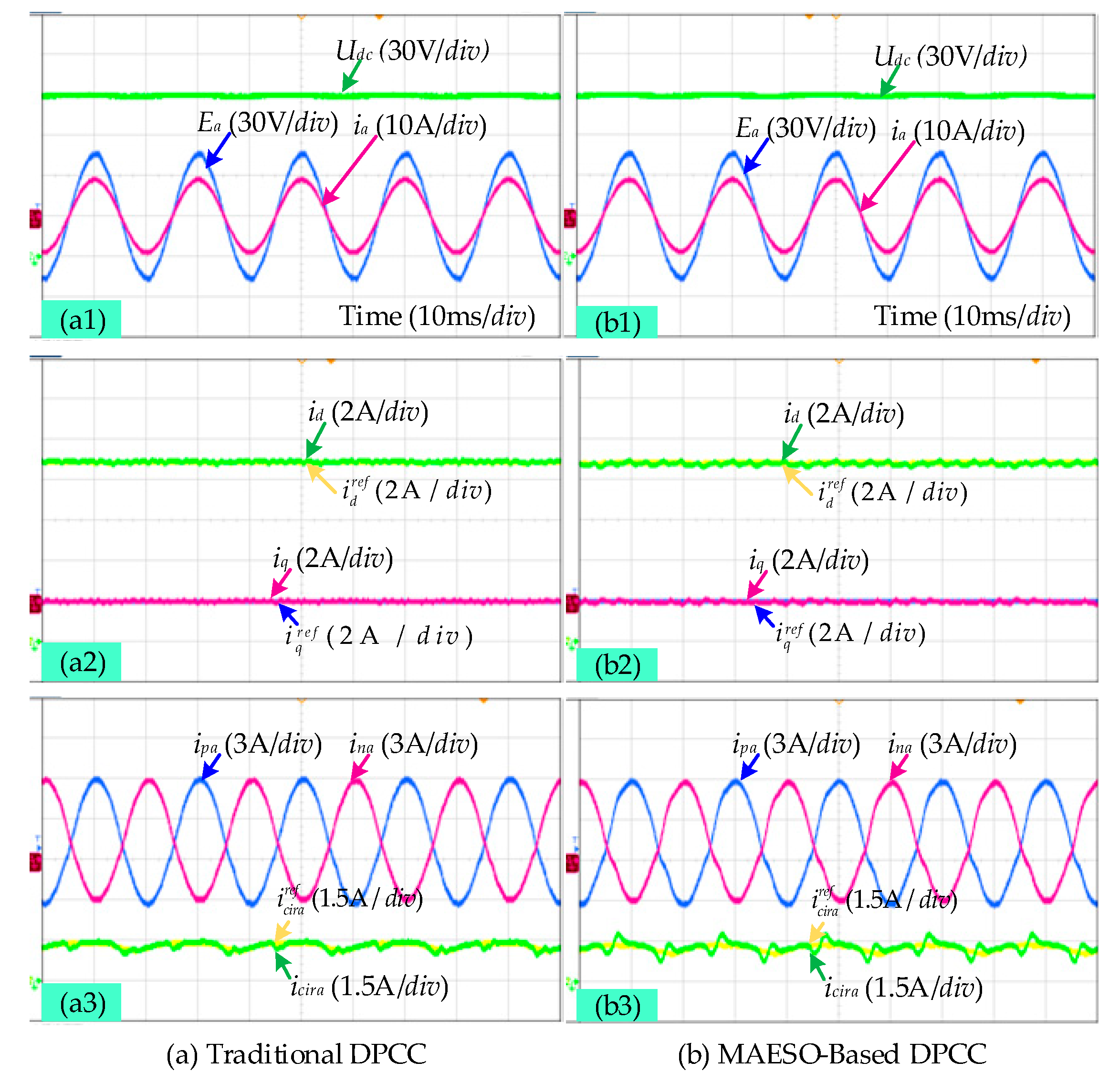
4. Experimental Results

To verify the effectiveness and feasibility of the MAESO-based DPCC strategy proposed in this paper, an experimental platform was built based on the topology of the three-phase MMC shown in Figure 1 to test and compare the traditional DPCC strategy and proposed control strategy. The experimental platform is shown in Figure 6. The digital controller uses a digital signal processor (DSP) and a field programmable gate array (FPGA). The DSP is mainly responsible for implementing the control algorithm, while FPGA is mainly responsible for generating PWM signals. The relevant parameters of the experimental platform are shown in Table 1. In the experiment, the MMC operated in rectifier state. At the same time, to better verify the effectiveness of the current control strategy, this paper calculates the reference values of the AC-side current and the circulating current of the MMC operating in the current loop mode using a manually set fixed power reference value.

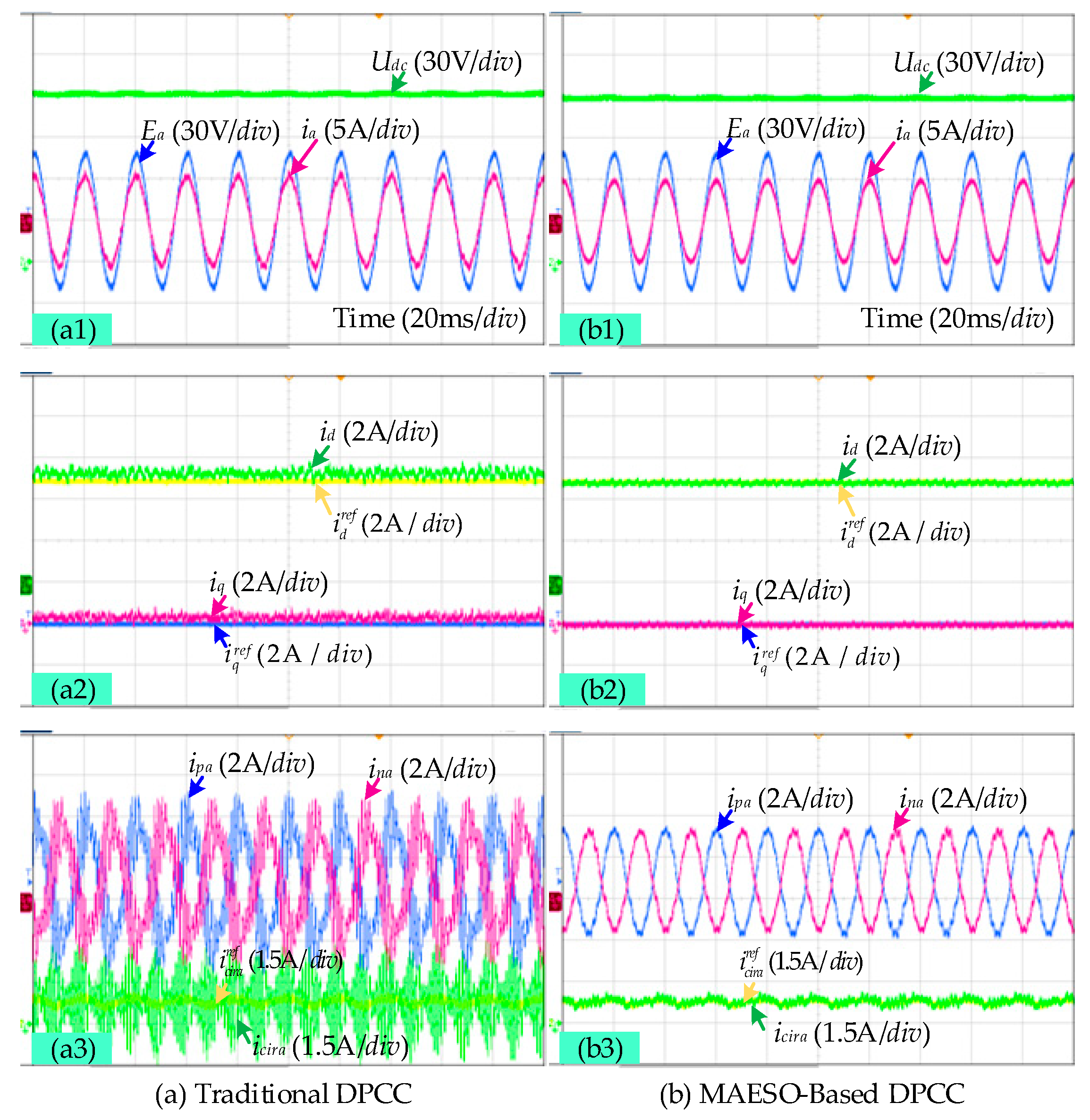
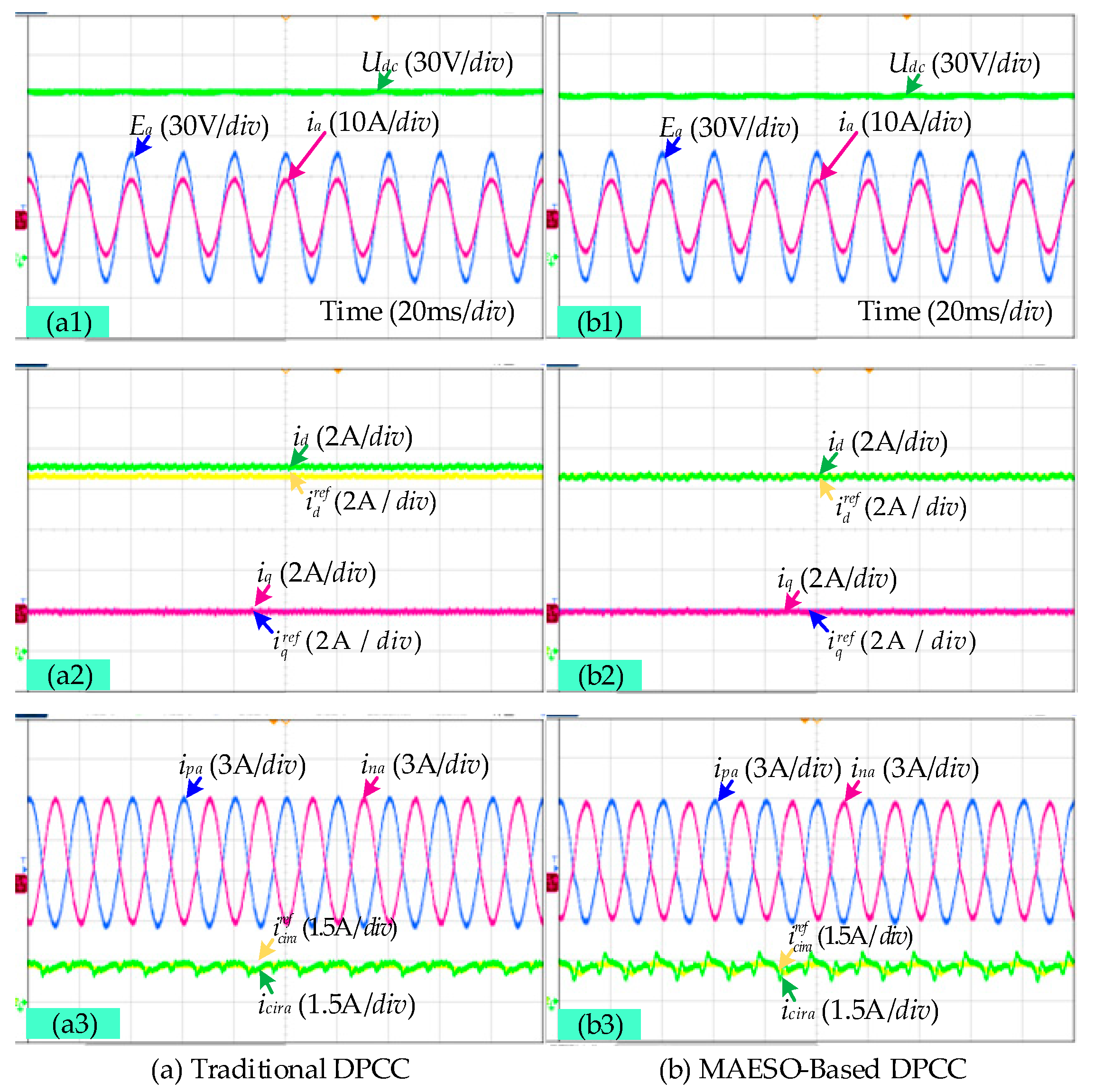
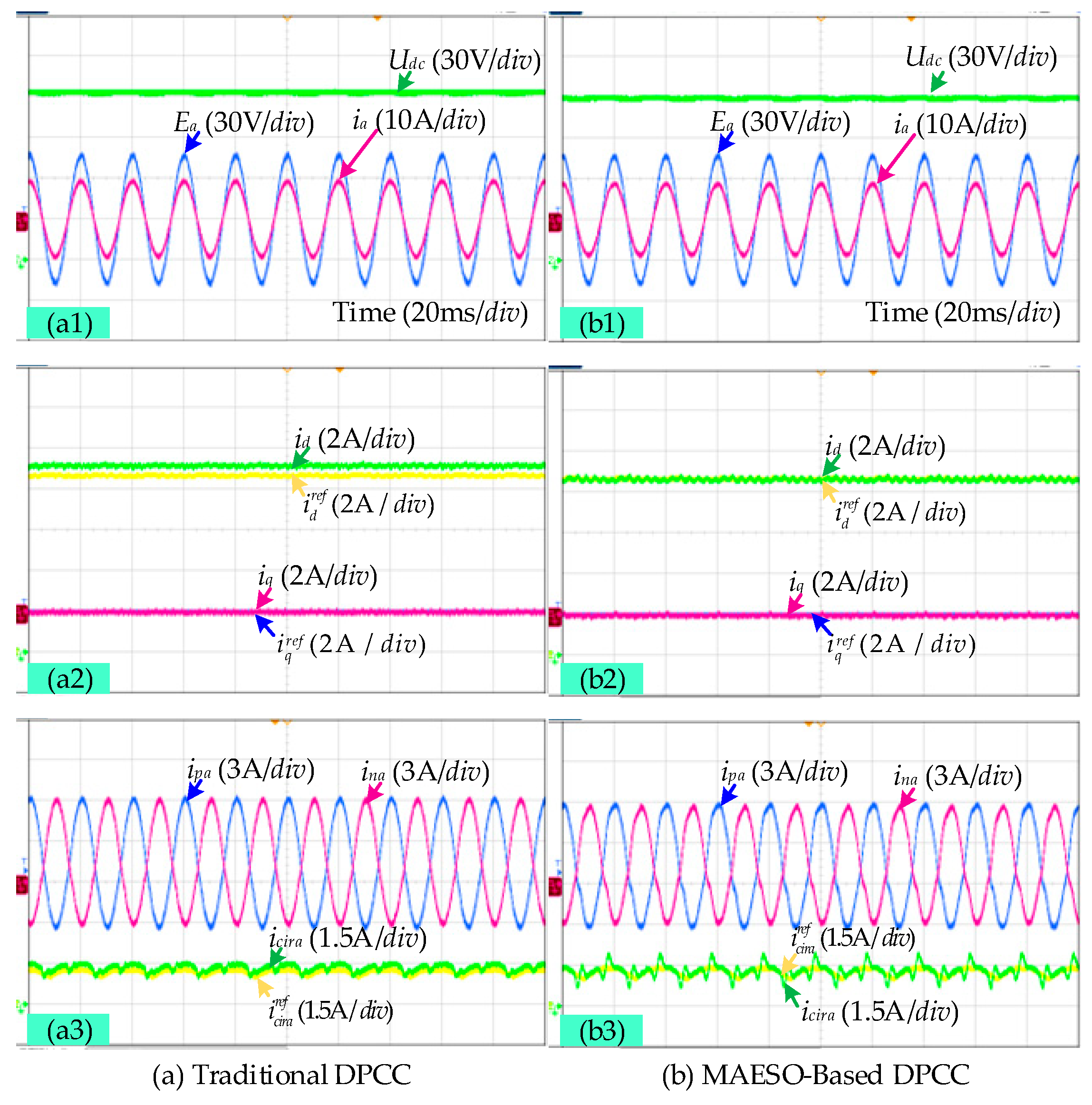
4.1. Steady-State Performance Comparison

Figure 7a,b show the experimental waveforms of the traditional DPCC and proposed MAESO-based DPCC strategy with a 30 Ω resistive load on the MMC’s DC side, respectively, in which the system active power reference value Pref is set to 600 W, and the reactive power reference value Qref is set to 0 Var. In the experiment, the circuit parameters used in the control system were consistent with the actual circuit parameters. According to the experimental results, both control strategies can effectively achieve the control objectives under steady-state conditions. The AC-side phase current ia and phase grid voltage Ea of the MMC are of the same frequency and phase. The actual values for the d-axis current id, q-axis current iq, and internal circulating current in phase a icira can all track their respective reference values well. In addition, comparing (a3) with (b3) in Figure 7, it can be seen that the internal circulating current of phase a icira determined using the MAESO-based DPCC strategy fluctuates slightly more than that determined using the traditional DPCC strategy.
Figure 8a,b show the analysis results derived from applying the fast Fourier transform (FFT) to the current ia on the AC side corresponding to the two control strategies. Figure 8 shows that the total harmonic distortion (THD) of the ia corresponding to the two control strategies is almost equal, with a THD of 0.5% being achieved when using the traditional DPCC strategy, while a THD of 0.6% was achieved when using the proposed MAESO-based DPCC strategy. Both control strategies ensure that the AC-side current of the MMC has a good sinusoidal degree.
The above steady-state performance experimental comparison results show that the traditional DPCC strategy has superior steady-state performance without circuit parameter deviation, and the steady-state performance of the proposed MAESO-based DPCC strategy is basically equivalent to that of the traditional DPCC strategy.

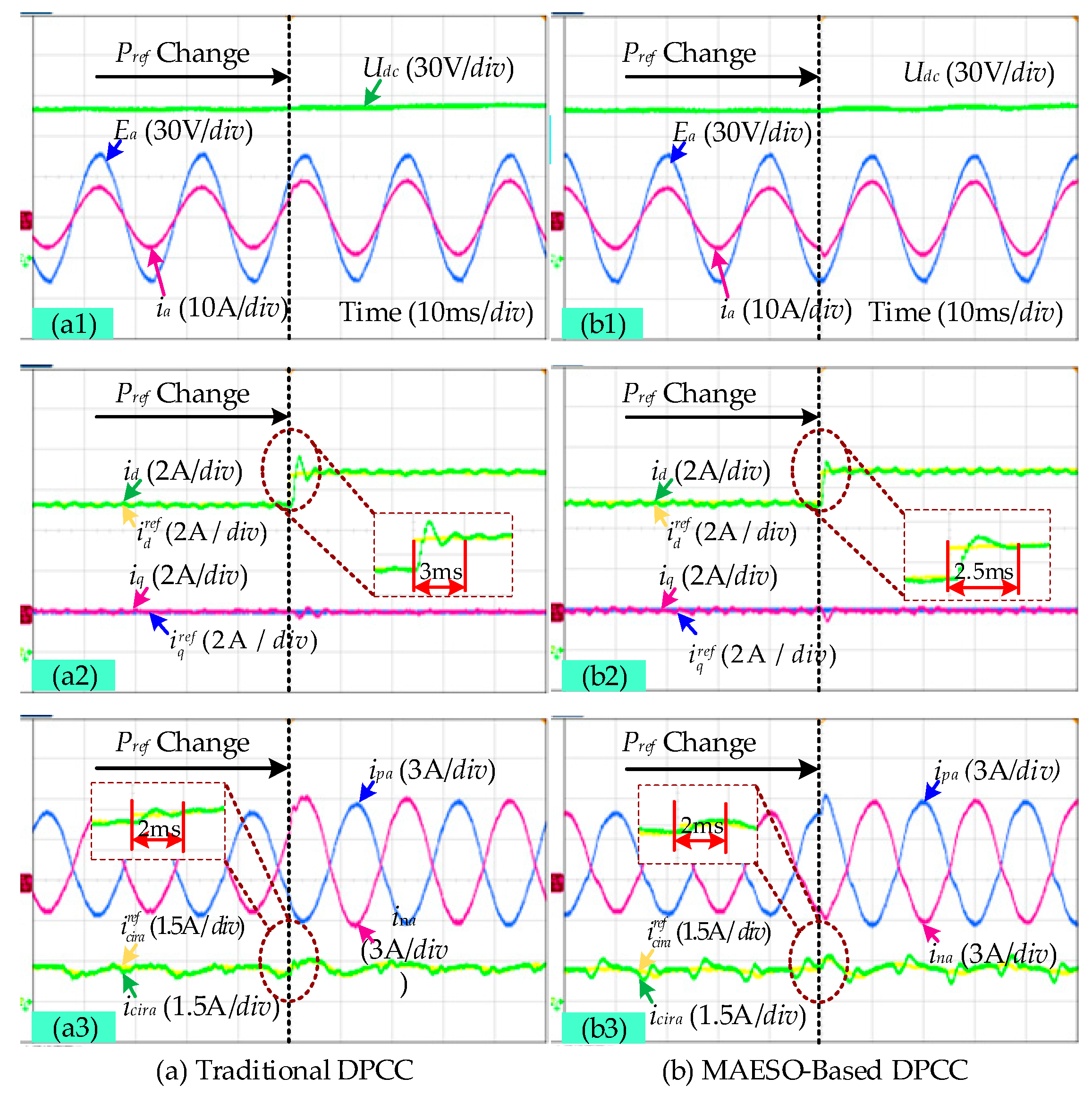
4.2. Dynamic Performance Comparison

Figure 9a,b show experimental waveforms corresponding to the traditional DPCC strategy and the proposed MAESO-based DPCC strategy when the system active power reference value Pref suddenly changes from 500 W to 600 W. In the experiment, the circuit parameters used in the control system remained consistent with the actual circuit parameters; a 30 Ω resistive load was connected to the MMC’s DC side, and the reactive power reference value Qref was set to 0 Var. As shown in Figure 9, when using the traditional DPCC strategy, the adjustment times for the d-axis current id and internal circulating current icira were found to be 3 ms and 2.5 ms, respectively. When using the proposed ESO-based DPCC strategy, the adjustment times for the d-axis current id and internal circulating current icira were both found to be 2 ms.
The experimental results derived from our dynamic performance comparison show that, without circuit parameter deviation, the proposed MAESO-based DPCC strategy has almost the same dynamic performance as the traditional DPCC strategy in the case of sudden changes in the active power reference value.

4.3. Robust Performance Comparison under Parameter Changes

To further test the control performance of the traditional DPCC strategy and proposed MAESO-based DPCC strategy under changes in the circuit parameters, the authors of this paper simulated the actual changes in circuit parameters by changing the circuit parameters in the control strategy.
Figure 10a,b show the experimental results of the two control strategies when the AC-side inductance is L ˜ a c = 8 mH and the arm inductance is L ˜ a r m = 8 mH. In the experiment, the DC side of the MMC was loaded with a 50 Ω resistor, the reference value of the active power Pref was set to 350 W, and the reference value of the reactive power Qref was set to 0 Var. Figure 10 shows that when using the traditional DPCC strategy, in the case of mismatched parameters of AC-side inductance and arm inductance, the a-phase input current ia, d-axis current id, and q-axis current iq all oscillate. Although the circulating current icira can still track the reference value to a certain extent, both the upper arm current ipa and the lower arm current ina undergo serious distortion. When using the proposed MAESO-based DPCC strategy, the d-axis current id, q-axis current iq, and circulating current icira can still track their respective reference values well. Moreover, the input current ia of phase a, the upper arm current ipa, and the lower arm current ina can also maintain a good sine degree.
Figure 11a,b show the experimental results of the two control strategies under an arm inductance value of L ˜ a r m = 11 mH. In the experiment, the DC side of the MMC was loaded with a 50 Ω resistor, the reference value of active power Pref was set to 350 W, and the reference value of reactive power Qref was set to 0 Var. As shown in Figure 11, when using the traditional DPCC strategy, in the case of mismatched arm inductance parameters, the circulating current icira oscillates and cannot track the reference value. In addition, although the input current ia maintains a good sine degree, the d-axis current id and q-axis current iq cannot track their respective reference values due to the influence of circulating currents, resulting in steady-state errors. When using the proposed MAESO-based DPCC strategy, the d-axis current id, q-axis current iq, and circulating current icira can still track their respective reference values well, and the input current ia, upper arm current ipa, and lower arm current ina can still maintain a good sine degree.
Figure 12a,b show the steady-state experimental results of the two control strategies when R ˜ a c = 1.5 Ω. In the experiment, the DC side of the MMC was loaded with a 30 Ω resistor, the reference value of active power Pref was set to 600 W, and the reference value of reactive power Qref was set to 0 Var. According to Figure 12, when using the proposed MAESO-based DPCC strategy, in the case of AC-side resistance mismatch, the d-axis current id, q-axis current iq, and circulating current icira can still track their respective reference values well, and the input current ia, upper arm current ipa, and lower arm current ina of phase a can maintain a good sinusoidal degree. However, when using the traditional DPCC strategy, the d-axis current id cannot track its reference value, resulting in steady-state error.
Figure 13a,b show the experimental results of the two control strategies when the arm resistance is R ˜ a r m = 3 Ω. In the experiment, the DC side of the MMC was loaded with a 30 Ω resistor, the reference value of active power Pref was set to 600 W, and the reference value of reactive power Qref was set to 0 Var. Figure 13 shows that when using the proposed MAESO-based DPCC strategy, in the event of arm resistance mismatch, the d-axis current id, q-axis current iq, and circulating current icira can still track their respective reference values well, and the input current ia, upper arm current ipa, and lower arm current ina of phase a can also maintain a good sine degree. However, when using the traditional DPCC strategy, the d-axis current id and the internal circulating current of phase a icira cannot track their reference values, resulting in steady-state errors.
The above experimental results indicate that compared to the traditional DPCC strategy, the MAESO-based DPCC strategy proposed in this paper can ensure that the d-axis current id, q-axis current iq, and circulating current of phase a icira can better track their respective reference values when circuit parameters change, allowing the MMC to maintain normal operation and have stronger robustness.

5. Conclusions

The control performance of the traditional DPCC strategy applied to MMCs is easily affected by changes in the circuit parameters. To improve the robustness of the system under changes in circuit parameters, this paper proposes an MAESO-based DPCC strategy to regulate the AC-side current and internal circulating current of the MMC. A comparative study was conducted on the proposed MAESO-based DPCC strategy and traditional DPCC strategy through the use of an experimental platform. The experimental results show that the MAESO-based DPCC strategy not only inherits the superior AC-side steady-state performance and fast dynamic response characteristics of the traditional DPCC strategy but also ensures that the d-axis current id, q-axis current iq, and internal circulating current can track their respective reference values well even when the circuit parameters change, making the MMC maintain normal operation and have stronger robustness. Also, it should be noted that when adopting MAESO-based DPCC strategy, the circulating current’s ripple is slightly larger than that of the traditional DPCC strategy. Thus, our subsequent research work will aim to address this issue on the basis of the proposed MAESO-based DPCC strategy.

Author Contributions

Methodology, X.Y., Y.Z., and Y.L.; Validation, X.Y. and S.J.; Writing and Editing, X.Y. and S.J.; Review, Y.Z. and Y.L. All authors have read and agreed to the published version of the manuscript.

Funding

This research received no external funding.

Data Availability Statement

Data are unavailable due to privacy reasons.

Conflicts of Interest

All authors were employed by Chengdu Aircraft Industrial (Group) Co., Ltd. And they declare that the research was conducted in the absence of any commercial or financial relationships that could be construed as a potential conflict of interest.

References

  1. Gao, X.; Tian, W.; Yang, Q.; Chai, N.; Jose, R.; Ralph, K.; Marcelo, L. Model predictive control of a modular multilevel converter considering control input constraints. IEEE Trans. Power Electron. 2024, 39, 636–648. [Google Scholar] [CrossRef]
  2. Wan, Y.; Yan, L.; Jiang, J. Modular multilevel converter-based power system for more electric aircraft. Power Electron. 2020, 54, 83–88. (In Chinese) [Google Scholar]
  3. Chen, X.; Li, Z.; Zhao, S.; Wei, X.; Kang, L. Design and implementation of a modular multilevel converter with hierarchical redundancy ability for electric ship MVDC system. IEEE J. Emerg. Sel. Top. Power Electron. 2017, 5, 189–202. [Google Scholar] [CrossRef]
  4. Chen, J.; Zhao, Y.; Lin, H.; Wei, Y.; Liu, W.; Guo, Q.; Li, R.; Mantooth, H.A. Analysis and control of cascaded energy storage system for energy efficiency and power quality improvement in electrified railways. IEEE Trans. Transp. Electrif. 2024, 10, 1299–1313. [Google Scholar] [CrossRef]
  5. Chen, J.; Hu, H.; Wang, M.; Ge, Y.; Wang, K.; Huang, Y.; Yang, K.; He, Z.; Xu, Z. Power flow control-based regenerative braking energy utilization in AC electrified railways: Review and future trends. IEEE Trans. Intell. Transp. Syst. 2024, 25, 6354–6365. [Google Scholar] [CrossRef]
  6. Hu, H.; Liu, Y.; Yang, X.; Li, Y.; Li, Z.; Zhu, X. A decentralized coordinated control strategy for multiple traction substations in MVDC railway power supply system. IEEE Trans. Transp. Electrif. 2024, 10, 3246–3257. [Google Scholar] [CrossRef]
  7. Chen, J.; Yang, K.; Lin, H.; Wang, K.; Cai, C.; Zhang, P. Star-connection supercapacitor-embedded CHMC-based STATCOM for electrified railways. IEEE Trans. Power Electron. 2024, 39, 13733–13743. [Google Scholar] [CrossRef]
  8. Yuan, B.; Xu, J.; Zhao, C.; He, Z.; Pang, H.; Ma, W. Optimal design of PR circulating current suppressing controllers for modular multilevel converters. Proc. CSEE 2015, 35, 2567–2575. (In Chinese) [Google Scholar]
  9. Li, T.; Yao, L.; Zhang, S. Improved two-stage mode predictive control for modular multilevel converters. Electr. Power Autom. Equip. 2024, 44, 562–570. (In Chinese) [Google Scholar]
  10. Yang, X.; Yang, F.; Xue, H.; Jiang, Y.; Bao, W.; Zhang, J. Duty-cycle modulation based model predictive control of modular multilevel converter. Autom. Electr. Power Syst. 2021, 45, 134–142. (In Chinese) [Google Scholar]
  11. Yang, X.; Xu, Y.; Yang, F.; Wang, T.; Yang, S.; Xue, H. Hierarchical model predictive control method based on finite state for modular multilevel converter. Autom. Electr. Power Syst. 2020, 44, 148–155. (In Chinese) [Google Scholar]
  12. Lin, H.; Wand, Z. A backward prediction based model predictive control strategy for modular multilevel converters. Proc. CSEE 2017, 37, 5098–5106. (In Chinese) [Google Scholar]
  13. Wand, J.; Tang, Y.; Lin, P.; Liu, X.; Josep, P. Deadbeat predictive current control for modular multilevel converters with enhanced steady-state performance and stability. IEEE Trans. Power Electron. 2020, 35, 6878–6894. [Google Scholar]
  14. Rong, F.; Gong, X.; Huang, S.; Luo, D. The deadbeat control strategy of modular multilevel converter. Proc. CSEE 2017, 37, 1753–1764. (In Chinese) [Google Scholar]
  15. Guo, G.; Dai, P.; Gong, Z. Submodule unified pulse width modulated based optimized model predictive control for modular multilevel converters. Proc. CSEE 2017, 37, 1478–1488. (In Chinese) [Google Scholar]
  16. Gong, Z.; Wu, X.; Dai, P.; Zhu, R. Modulated model predictive control for MMC-based active front-end rectifiers under unbalanced grid conditions. IEEE Trans. Ind. Electron. 2019, 66, 2398–2409. [Google Scholar] [CrossRef]
  17. Lin, H.; Chung, H.; Shen, R.; Xiang, Y. Enhancing stability of DC cascaded systems with CPLs using MPC combined with NI and accounting for parameter uncertainties. IEEE Trans. Power Electron. 2024, 39, 5225–5238. [Google Scholar] [CrossRef]
  18. Xie, D.; Lin, C.; Deng, Q.; Lin, H.; Cai, S.; Thomas, B.; Ge, X. Simple vector calculation and constraint-based fault-tolerant control for a single-phase CHBMC. IEEE Trans. Power Electron. 2024. [Google Scholar] [CrossRef]
  19. Cai, X.; Zhao, C.; Pang, H.; Lin, C. A novel DC voltage control of MMC-HVDC power transmission system based on discrete mathematical model of MMC. Power Syst. Technol. 2013, 37, 2403–2409. (In Chinese) [Google Scholar]
  20. Lin, H.; Niu, S.; Xue, Z.; Wang, S. A simplified virtual-vector-based model predictive control technique with a control factor for three-phase SPMSM drives. IEEE Trans. Power Electron. 2023, 38, 7546–7557. [Google Scholar] [CrossRef]
  21. Han, J. Active Disturbance Rejection Control Technique: The Technique for Estimating and Compensating the Uncertainties; National Defense Industry Press: Beijing, China, 2008. [Google Scholar]
  22. Hang, J. From PID to active disturbance rejection control. IEEE Trans. Ind. Electron. 2009, 56, 900–906. [Google Scholar]
  23. Gao, Z. Scaling and bandwidth parameterization based on control tuning. In Proceedings of the 2004 American Control Conference, Denver, CO, USA, 4–6 June 2003; pp. 4989–4996. [Google Scholar]
  24. Zhu, B. Introduction to Active Disturbance Rejection Control; Beihang University Press: Beijing, China, 2017. [Google Scholar]
  25. Zhang, Y.; Li, B.; Liu, J.; Liu, X.; Li, B. Model-free predictive current control of PWM rectifier Under unbalance and distorted network. In Proceedings of the 2020 IEEE Energy Conversion Congress and Exposition (ECCE), Detroit, MI, USA, 11–15 October 2020; pp. 5944–5951. [Google Scholar]
  26. Zhang, Y.; Jin, J.; Huang, L. Model-free predictive current control of PMSM drives based on extended state observer using ultralocal model. IEEE Trans. Ind. Electron. 2021, 68, 993–1003. [Google Scholar] [CrossRef]
  27. Yuan, X.; Zuo, Y.; Fan, Y.; Lee, C.H.T. Model-free predictive current control of SPMSM drives using extended state observer. IEEE Trans. Ind. Electron. 2022, 69, 6540–6550. [Google Scholar] [CrossRef]
Figure 1. The topology structure of a three-phase MMC.
Electronics 13 03789 g001
Figure 2. The equivalent circuit of the MMC. (a) AC-side equivalent circuit. (b) DC-side equivalent circuit.
Electronics 13 03789 g002
Figure 3. Discrete block diagram of the MAESO for the d- and q-axis subsystems.
Electronics 13 03789 g003
Figure 4. Discrete block diagram of the MAESO for estimating icirj and fdcirj.
Electronics 13 03789 g004
Figure 5. Overall control block diagram of MAESO-based DPCC strategy for MMCs.
Electronics 13 03789 g005
Figure 6. A photograph of the MMC experimental platform.
Electronics 13 03789 g006
Figure 7. The steady-state experimental results of the two control strategies in the steady state.
Electronics 13 03789 g007
Figure 8. FFT analysis results of ia for two control strategies.
Electronics 13 03789 g008
Figure 9. The experimental results of the two control strategies under sudden active power change conditions.
Electronics 13 03789 g009
Figure 10. The steady-state experimental results of the two control strategies when L ˜ a c = 8 mH and L ˜ a r m = 8 mH.
Electronics 13 03789 g010
Figure 11. The steady-state experimental results of the two control strategies when L ˜ a r m = 11 mH.
Electronics 13 03789 g011
Figure 12. The steady-state experimental results of the two control strategies when R ˜ a c = 1.5 Ω.
Electronics 13 03789 g012
Figure 13. The steady-state experimental results of the two control strategies when R ˜ a r m = 3 Ω.
Electronics 13 03789 g013
Table 1. Experimental platform parameters.
ParameterSymbolValue
Line-to-line voltage at MMC side of isolated transformer T (RMS Value)Erms60 V
AC-side inductorLac3 mH
AC-side resistorRac0.5 Ω
Arm inductorLarm5 mH
Arm resistorRarm1.0 Ω
SM capacitorCsm4.4 mF
DC-side capacitorCdc3 mF
Number of SMs per armN4
Carrier frequency of PSC-PWMfcir4 kHz
Control periodTs125 μs
Bandwidth of ESOω01200
Disclaimer/Publisher’s Note: The statements, opinions and data contained in all publications are solely those of the individual author(s) and contributor(s) and not of MDPI and/or the editor(s). MDPI and/or the editor(s) disclaim responsibility for any injury to people or property resulting from any ideas, methods, instructions or products referred to in the content.

