Article

LCC-HVDC Frequency Robust Control Strategy Based on System Parameter Identification in Islanded Operation Mode

1
Electric Power Research Institute of Yunnan Power Grid Co., Ltd., Kunming 650011, China
2
College of Electrical Engineering, Sichuan University, Chengdu 610065, China
*
Author to whom correspondence should be addressed.
Electronics 2024, 13(5), 951; https://doi.org/10.3390/electronics13050951
Submission received: 7 February 2024 / Revised: 26 February 2024 / Accepted: 28 February 2024 / Published: 1 March 2024
(This article belongs to the Section Industrial Electronics)

Abstract

:
To enhance the stability of the frequency at the sending terminal of the HVDC island during operation, a novel DC supplemental frequency robust controller is proposed in this paper. The proposed controller utilizes the fast controllability of a DC power supply to maintain system frequency stability. The identification of a low-order linearized model of the system can be obtained from a high-precision Prony algorithm based on the second derivative method (SDM). Subsequently, utilizing a robust design methodology based on linear matrix inequalities, an additional frequency robust controller is devised, striking a balance between optimal performance and robustness. This supplementary frequency robust controller exhibits a straightforward control structure with a modest order, making it readily implementable. Simulation experiments conducted within the PSCAD/EMTDC framework substantiate that the designed supplemental frequency robust controller significantly enhances the frequency stability of the sending terminal system. Furthermore, when compared with traditional proportional integral (PI) controllers, it demonstrates superior control efficacy and robustness against various types of faults under different operational modes. Even in interconnected operational modes, it continues to operate effectively. The research findings offer valuable insights for practical applications in islanded power systems.

1. Introduction

Under high-voltage DC (HVDC) transmission systems, island operation is the term applied when the sending-end system primarily consists of several major power plants and a cluster of sending-end converter stations [1,2]. The unique energy and load distribution characteristics inherent to HVDC transmission systems make them exceptionally well-suited for long-distance high-capacity transmission, leading to their widespread adoption. Therefore, the DC island operation mode is frequently encountered, particularly in large hydroelectric or thermal power plants situated a considerable distance from urban centers [3,4,5,6]. Moreover, maintenance and fault-related factors can also prompt a shift from interconnected operation to island operation. During HVDC island operation, its frequency will be unstable due to the weak AC system, the reduced short-circuit capacity, and unbalanced power owing to the disturbances in AC and DC systems. This instability, in turn, has the potential to trigger more severe faults and destabilize the entire system. Consequently, the pursuit of research in HVDC supplementary frequency control to enhance the frequency stability of DC island sending-end systems holds paramount significance [7].
In [8], it is elucidated that frequency limitation control (FLC) holds profound significance in the realm of frequency regulation for extensive HVDC asynchronous interconnected power grids. It is pointed out that FLC can quickly reduce the unbalanced power of faults and limit frequency deviation during transient processes, with good response capability. However, in the intricate realm of FLC, the orchestration of the dead zone (DZ) stands as a complex symphony, intertwining with the nuanced melodies of primary frequency regulation and its auxiliary components. As explored in [9], multiple FLC maestros are summoned to control the rhythms of various HVDC transmission lines. Through the balancing of FLC reserve allocation, DZ adjustments, and parameter fine-tuning (in harmony with primary frequency modulation), these collectives aim to masterfully reduce frequency deviations. In [10], a sophisticated objective function is introduced, likened to a composer crafting a masterpiece, aimed at fine-tuning the FLC DZ’s impact on frequency stabilization and the balance of HVDC systems. The NSGA-II algorithm is employed as the oracle to discover the optimal DZ parameters for FLC. In addition, the control mechanism of the LCC-HVDC system has been improved and can enhance the stability of the system. Ref. [11] introduces a PID damping controller, inspired by modal control theory, applied to the converter station of LCC-HVDC, promising improved damping. Ref. [12] presents an advanced SFR model as the foundation for a comprehensive FLC strategy, heralding a new era of stability and harmony in the dynamic symphony of electrical power systems. This approach effectively elevates the frequency stability of the transmission system while mitigating the shortcomings of conventional FLC. However, all the mentioned frequency control strategies above employ traditional PI controllers, which require a certain level of expertise and finesse in tuning controller parameters. Furthermore, PI controllers exhibit sensitivity to changes in system operating conditions, affecting control effectiveness and displaying limited robustness.
In [13], a conventional PID controller is employed to establish an inner and outer cascaded controller. The proposed controller is used for load frequency control (LFC) of a two-area power grid, including thermal reheat units, wind turbines, and hydroelectric power plants. Utilizing the enhanced knowledge-based optimization differential evolution algorithm, this approach is employed for controller refinement. In comparison with traditional single-loop PI and PID controllers, it has yielded a notable improvement in system performance. In [14], a proportional derivative with network filter (PDN) is combined with a cascaded PDN-PI controller for the outer loop, introducing a sophisticated approach to control mechanisms. The coyote optimization technique, inspired by the adaptability and social dynamics of coyotes, is utilized to precisely tune the controllers for LFC in multi-area electrical grids. This advanced method has demonstrated superior performance, outpacing traditional single-loop PI and PID controllers. In [15], a cascaded PI and fractional order PID (FPID) controller is proposed to enhance the frequency response of a two-area hybrid power grid system, which includes solar panels, wind turbines, and energy storage systems. The proposed controller utilizes the gorilla troops optimizer to determine the optimal parameters. This method is based on the collaborative and strategic behaviors observed in gorilla groups. Ref. [16] introduces a novel cascaded FPI-FPD controller, which is optimized using the dragonfly search algorithm. This innovative controller is designed to improve LFC in power systems, drawing inspiration from the dragonfly’s precision and agility in flight to enhance the stability and efficiency of power grids. The traditional FLC control with cascaded controllers yields good results. However, the controller with a multi-module cascaded-control structure requires iterative parameter adjustment based on engineering experience to achieve the optimal control effect.
This paper is organized based on the SDM-Prony algorithm with high computational accuracy to construct an accurate low-order linearization model of the system. Subsequently, by employing the robust control design method rooted in linear matrix inequalities (LMI) and integrating it with regional pole placement techniques, while concurrently addressing the controller’s robustness and optimal performance, a DC supplementary frequency robust controller has been artfully crafted. The contributions of this endeavor are eloquently outlined as follows:
  • The establishment of the low-order linearization model of the system in this paper is achieved through the SDM-Prony algorithm. Subsequently, robust control is proposed based on linear matrix inequality (LMI).
  • Robustness issues and solutions for optimizing controller performance are proposed through the adoption of regional pole placement methods.
  • The proposed supplementary frequency robust controller significantly reduces system frequency fluctuations, improves system frequency stability, and has superior control effects and higher robustness.
This paper is organized as follows: Section 2 introduces the robust control theory pertaining to DC transmission systems featuring supplementary frequency control. Section 3 expounds upon the island model identification, which is grounded in the SDM-Prony algorithm. Section 4 is dedicated to the design of supplementary frequency robust controllers. Section 5 presents both simulation and experimental findings. Section 6 concludes with a comprehensive summary of the supplementary frequency robust controller meticulously designed within the context of this manuscript.

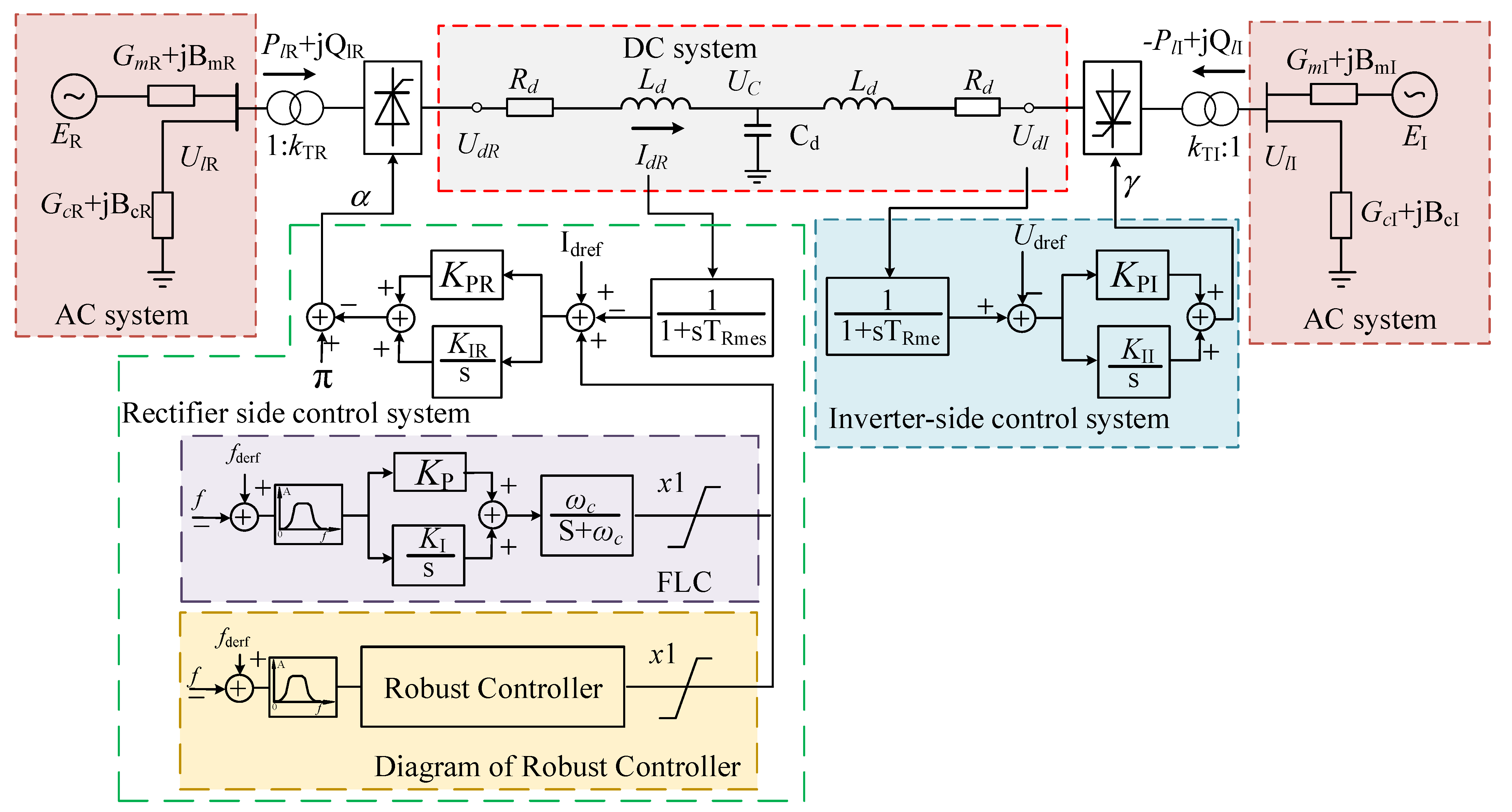
2. Control Framework of DC Transmission Systems with Additional Frequency Control

2.1. HVDC System with Frequency Control

The fundamental control methods of HVDC transmission systems may ensure stable static operation. However, when disturbed or if a fault occurs, the subsequent dynamic process will not be effectively controlled; hence, it is customary to install supplementary DC controllers. This practice serves a dual purpose; the approach significantly enhances the inherent dynamic stability of the DC transmission system, while also markedly improving the dynamic stability of the AC system.
Taking the asynchronous interconnection system formed by the LCC-HVDC connection, as illustrated in Figure 1, as an example, its model comprises the components of the DC transmission lines and the control systems on the converter station, as well as the AC systems on the converter station. The rectifier side employs constant current control. Given that DC power is determined by both DC voltage and DC, the regulation of DC power primarily occurs through the automatic adjustment of the triggering angle by altering the reference value of the rectifier side current regulator. This, in turn, modifies the DC and regulates DC power, thus controlling the frequency of the AC system. In the diagram, the rectifier and inverter sides are represented by their respective network equivalent sources, AC line equivalent conductance, AC line equivalent susceptance, ground-to-AC equivalent conductance, and ground-to-AC equivalent susceptance, along with the active and reactive power transmissions, denoted as ER, GmR, BmR, GcR, BcR, PlR, QlR and EI, GmI, BmI, GcI, BcI, PlI, QlI, respectively. The direct current line’s equivalent resistance, inductance, and ground capacitance are symbolized by Rd, Ld, and Cd. The voltages at the transformer network side for the rectifier and inverter, as well as the direct current voltages for both, are indicated by UlR, UlI, UdR, and UdI. The transformer turn ratios for the rectifier and inverter sides are expressed as 1:kTR and 1:kTI, respectively, with TRmes and TRme representing the time constants of the first-order inertial elements on the rectifier and inverter sides. The measured and set values of DC current are given by Idr and Idref. The proportion, KPR, KP, KPI, and integral time constant in the controller are represented by KI, KIR, and KII, respectively. The firing angles for the rectifier and inverter sides are symbolized by α and γ, while the measured and nominal frequencies are indicated by f and fderf.
Traditional supplementary frequency regulation entails augmenting the constant current control on the rectifier side with the addition of a field-level controller (FLC). This harnesses the FLC to adjust the reference value of DC, synchronizing it with the fixed voltage control on the inverter side, thereby modulating the DC power and participating in the frequency regulation of the interconnected electrical grids on both sides. Conventional FLC, employing PI control, faces challenges in setting the PI values. Furthermore, PI controllers exhibit sensitivity to changes in the system’s operating modes, which can impact control effectiveness.
Robust controllers for frequency regulation are crafted based on the distinct transfer functions of various systems, customized for different control objectives. This tailored design of robust controllers ensures that the system possesses sufficient robustness and stability, allowing it to effectively handle frequency regulation under various operational modes.

2.2. Robust Control Theory

On the basis of considering the general control system of additive model errors, the generalized control system of additive model errors is shown in Figure 2.
In Figure 2, G(s) represents the transfer function of the controlled object. K(s) corresponds to the transfer function of the designed robust controller w, which introduces uncertainties complicating the system’s model. u represents the control input, while y signifies the output. W1, W2, and W3 are weighting functions. Additionally, z∞1, z∞2, and z2 are utilized as output signals to assess both the system’s robustness and control performance. It can be defined z = [z∞1 z∞2]T, then the following state–space representation to describe the comprehensive control entity may be employed.
{ x ( t ) = M x ( t ) + N 1 w ( t ) + N 2 u ( t ) z ( t ) = P 1 x ( t ) + Q 11 w ( t ) + Q 12 u ( t ) z 2 ( t ) = P 2 x ( t ) + Q 21 w ( t ) + Q 22 u ( t ) y ( t ) = P x ( t ) + Q 1 w ( t ) + Q 1 u ( t )
The designed supplementary frequency robust controller is denoted as the output feedback controller K(s), and its state equation can be expressed as follows:
{ x ˙ ( t ) = M k x ( t ) + N k u ( t ) y ( t ) = P k x ( t )
Therefore, the closed-loop system containing the controller is illustrated as follows:
{ x cl ( t ) = M cl x xl ( t ) + N cl w ( t ) z ( t ) = P cl 1 x xl ( t ) + Q cl 1 w ( t ) z 2 ( t ) = P cl 2 x cl ( t ) + Q cl 2 w ( t )
where [ M cl N cl P cl 1 Q cl 1 P cl 2 Q cl 2 ] = [ M N 2 P k N 1 N k P 3 M k + N k Q 2 P k N k Q 1 N 1 Q 12 P k Q 11 N 2 Q 22 P k 0 ] and x cl = [ x x k ] T .
The closed-loop transfer function matrix from w to z as TwZ(s) and from w to z2 as TwZ2(s) is defined. In designing the controller presented in this paper, both the robustness and the performance of the controller are taken into consideration. The design objectives for this controller are established with these key aspects as priorities.
(1)
H performance.
When the H of Twz(s) is less than a given value γ, i.e., ||Twz(s)|| < γ, it ensures that the closed-loop system can meet the corresponding robust performance requirements concerning the uncertainties introduced by w. According to the bounded real lemma, the closed-loop system, as outlined in Equation (3), meets these performance criteria if, and only if, a symmetric positive definite matrix X1 exists that satisfies specific conditions in Equation (4).
[ M cl T X 1 + X 1 M cl X 1 N cl P cl 1 T N cl T X 1 γ I Q cl 1 T P cl 1 Q cl 1 I ] < 0
(2)
H2 performance.
To maintain a high level of control performance for the system, for a given positive constant μ, it is necessary to ensure that ||Twz2(s)|| < μ. This can be equivalently expressed as the existence of symmetric matrices X2 and A, meeting the requirements of Equation (5):
{ [ M cl T X 2 + X 2 M cl X 2 N cl N cl T X 2 I ] < 0 Trace ( A ) < μ 2 [ A P cl 2 X 2 X 2 P cl T X 2 ] > 0
(3)
Region-based pole location.
To guarantee that the closed-loop system exhibits optimal dynamic behavior and steady-state characteristics, the placement of system poles at specific positions within a complex plane becomes crucial during the controller design phase. The use of a region-based pole placement approach effectively mitigates potential inaccuracies in placing individual dominant poles due to errors in the system identification model. By adopting this method, the closed-loop poles are positioned within the designated area D on the complex plane, ensuring that the closed-loop system achieves the expected dynamic behavior and steady-state performance. For example, placing the closed-loop poles within the region D illustrated in Figure 3 ensures that the closed-loop system exhibits a minimum decay rate of α and a minimum damping ratio of φ = cos(θ).
In a certain region D in the complex plane, if there exists a symmetric matrix L ∈ Rm×m and a matrix U ∈ Rm×m, within a specified region D on the complex plane there should be a symmetric matrix L ∈ Rm×m and another matrix U ∈ Rm×m.
In this context, the specified region represents a linear matrix inequality (LMI) region. Specifically, region D, as depicted in Figure 3, functions as an LMI region. Regarding a given matrix A, the condition required for all its eigenvalues to fall within the designated LMI region D is the existence of a symmetric positive definite matrix X meeting as follows: L X + U ( M X ) + U T ( M X ) T < 0 .
For Figure 3, the necessary and sufficient condition for the closed-loop system poles shown in Equation (3) to be all located in region D is the existence of a symmetric positive definite matrix X3. and the condition of X3 meets Equation (6):
{ M cl X 3 + X 3 M cl T + 2 α X 3 < 0 [ sin θ ( M cl X 3 + X 3 M cl T ) cos θ ( M cl X 3 X 3 M cl T ) cos θ ( X 3 M cl T M cl X 3 ) sin θ ( M cl X 3 + X 3 M cl T ) ] < 0
(4)
Multi-objective control.
By simultaneously considering Equations (4)–(6) and setting X1 = X2 = X3 = X without imposing constraints on γ and η , the following function is optimized and solved:
min K ( s ) { a | | T w z ( s ) | | 2 + b | | T w z 2 ( s ) | | 2 2 }
Hence, the formulation of the robust output feedback controller, symbolized as K(s), empowers us to fulfill the diverse control objectives set for the closed-loop system. In this context, the variables a and b both represent performance weighting coefficients that reflect the respective weights assigned to the H and H2 performance aspects. Different values of a and b can be employed to emphasize distinct facets of controller performance. Normally, a = 0.6 and b = 0.4 are chosen to present a greater emphasis on robustness. The supplementary frequency robust controller, obtained through the aforementioned methodology, not only enhances system damping but also concurrently achieves a balance between optimal performance and robustness, thereby resulting in the optimal overall controller performance [17,18,19,20,21,22].

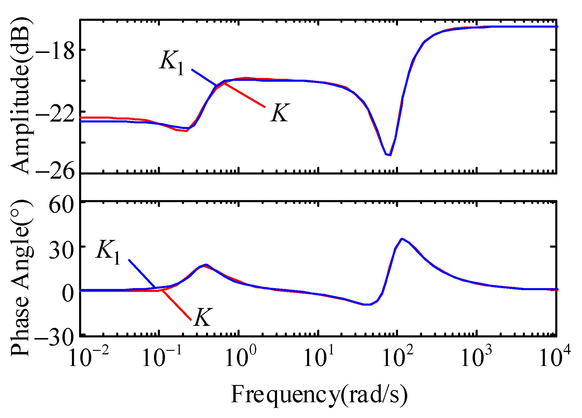
3. Island Model Identification Based on the SDM-Prony Algorithm

3.1. The SDM-Prony Identification Algorithm

Unlike the traditional PI controller design, which does not rely on an accurate mathematical model of the system, the robust controller is developed based on the linearized model of the system. Therefore, identifying the linearized model of the controlled system is a critical prerequisite before proceeding with the design of the supplementary frequency robust controller. The Prony algorithm can infer the system transfer function by analyzing the input and output signals of the system. This algorithm calculates the signal’s frequency, amplitude, phase, and other parameters by fitting data samples, and subsequently derives the system’s transfer function. However, the Prony identification algorithm has weaker anti-noise and anti-interference capabilities and low identification accuracy [23,24,25,26]. There are currently many improvements based on Prony, and SDM-prony is one of them. The SDM-Prony algorithm can effectively suppress noise interference and improve recognition accuracy by introducing spatial domain filters. Compared with the traditional Prony algorithm, the SDM-Prony algorithm has a smaller amount of calculation and can obtain the result faster. The implementation of the SDM-Prony algorithm is relatively simple and easy to apply in actual engineering.

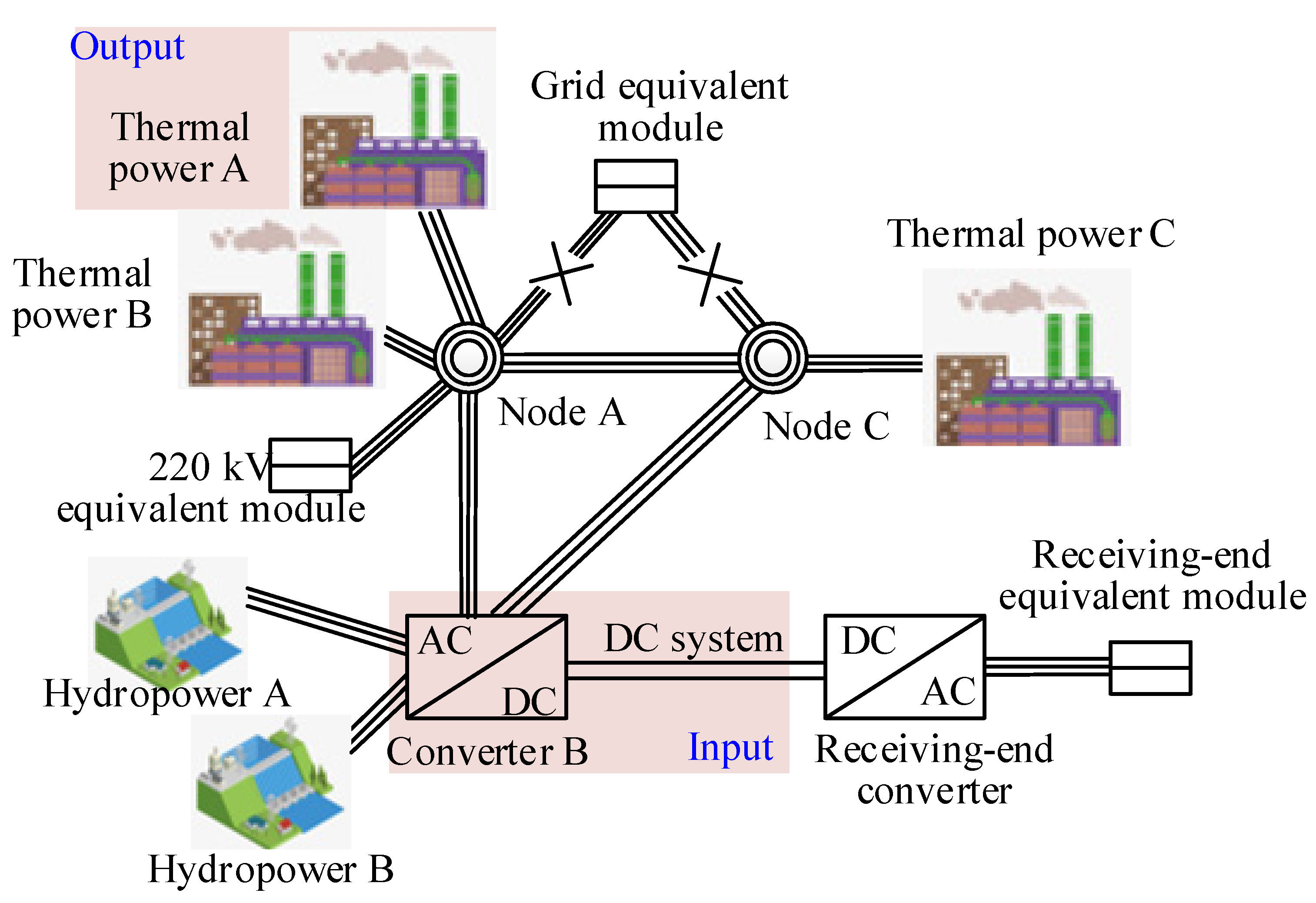
3.2. Identification of Island Simulation Models

The simulation model for the islanded operation of an actual power grid, constructed within the framework of PSCAD/EMTDC, is illustrated in Figure 4. When developing this electromagnetic transient model, primary consideration is given to the 500 kV transmission lines. Suitable equivalent representations are applied to the 220 kV lines and loads. Due to maintenance and fault-related factors, both the double-circuit 500 kV AC transmission lines connecting nodes A and C to the main grid are disconnected. This renders the sending end of the DC system as an islanded system. During islanded operation, there are two 600 MW units operating in both thermal power plants A and C. There is a 600 MW unit operating in thermal power plant B. Hydroelectric plants A and B remain offline. The DC system operates in a single-pole reduced power mode with a transmission capacity of 1600 MW. In the control scheme employed, the rectifier side operates under constant current control, while the inverter side utilizes constant extinction angle control. During islanded operation, the AC system at the sending end is relatively weak. Occurrences of AC and DC faults are prone to induce instability in the system’s frequency, posing a significant risk to stable system operation.
As depicted in Figure 4, when the system operates in a stable islanded condition, the minor step disturbance in the constant current control signal at the DC rectifier serves as the input. The frequency deviation of thermal power plant A in the sending-end AC system is the output. Furthermore, the transfer function of the system’s lower order linearized model can be identified in Equation (8) according to Figure 5.
The appropriate signal is selected as the input. Through the system input and output, the input and output are sampled, and the characteristic roots of the system are identified by the SDM-Prony algorithm. The output of the identified transfer function is compared to the original output. The error is correct within the allowable range in Figure 5.
G ( s ) = 9.148 s 6 + 341.3 s 5 + 76970 s 4 + 1   159000 s 3 + 813200 s 2 + 118800 s s 6 + 60.65 s 5 + 7107 s 4 + 3904 s 3 + 154300 s 2 + 52590 s + 10872

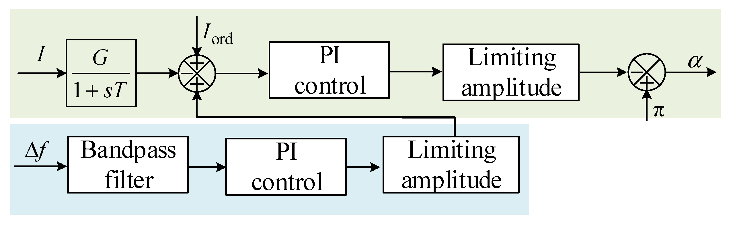
4. The Design of Supplementary Frequency Robust Controllers

4.1. The Design of the Controller

Incorporating an additional frequency robust controller into the DC system leverages the rapid controllability inherent in DC to mitigate or eliminate the active power imbalance during disturbances or faults, thus preserving frequency stability. The configuration of the supplementary frequency robust controller is illustrated in Figure 6. Within this design, a bandpass filter employs a Butterworth low-pass filter to effectively attenuate high-frequency interference signals, with a cutoff frequency set at 60 Hz, while the amplitude limiting section is set to 0.2. This controller is strategically placed at the constant current control point on the rectification side of the DC system. It uses the frequency deviation signal from thermal power plant A in the sending-end AC system as its input, generating an auxiliary current control signal as its output. This facilitates the swift adjustment of the DC system’s power transmission, thereby achieving the goal of damping the system’s frequency oscillations.

4.2. The Design of the Supplementary Frequency Robust Controller

In the process of developing a supplementary frequency robust controller, the weighting function of the intricate model is important. This choice ensures that the performance of the designed supplemental frequency robust controller meets the expected requirements. Generally, lower-order weighting functions should be preferred, with W1(s) exhibiting low-pass characteristics and W3(s) displaying high-pass characteristics. Additionally, the frequency bands of W1(s) and W3(s) should not overlap, while W2(s) is chosen as a relatively small constant [27]. The selected weighting functions in this study are as follows.
{ W 1 ( s ) = 1 s + 2 W 2 ( s ) = 0.0002 W 3 ( s ) = 20 s s + 15
Once the weighting functions have been properly established, then a region ‘D’ for pole placement is chosen, with a damping ratio greater than 0.3 and a minimum decay rate of α = 0.2. In Equation (7), a = 0.6, b = 0.4 is set without imposing any constraints on γ and μ. This yields the frequency robust controller as shown in Equation (10).
K ( s ) = 0.1479 s 8 + 1.647 × 10 7 s 7 + 1.047 × 10 11 s 6 + 6.062 × 10 12 s 5 s 8 + 1.094 × 10 8 s 7 + 7.078 × 10 11 s 6 + 9.723 × 10 13 s 5   7.104 × 10 14 s 4 + 2.239 × 10 15 s 3 + 2.105 × 10 15 s 2 + 5.779 × 10 14 s + 9.876 × 10 13 7.206 × 10 15 s 4 + 2.20 × 10 16 s 3 + 2.289 × 10 16 s 2 + 7.66 × 10 15 s + 1.3 × 10 15
The controller obtained has an excessively high order, rendering it impractical for real-world applications. We can address this issue by employing a reduced-order balancing truncation method to obtain the controller.
K 1 ( s ) = 0.1497 s 4 + 8.104 s 3 + 1008 s 2 + 323.4 s + 109.7 s 4 + 134.7 s 3 + 10060 s 2 + 4042 s + 1485
The Bode plot comparison of the supplementary frequency robust controller before and after dimensionality reduction is depicted in Figure 7. It can be observed from this illustration that the control performance of the designed controller remains unaltered after the dimensionality reduction.
After designing the robust controller, in comparison with the traditional supplementary frequency control methods, the conventional supplementary PI controller is designed, as utilized in [28]. Regarding the optimal PI parameters, the proportional parameter can be obtained through fine-tuning as 0.8, and the integral parameter is set to 2. Its structure is depicted in Figure 8, wherein the settings of the band-pass filter and saturation element are identical to those of the robust controller.

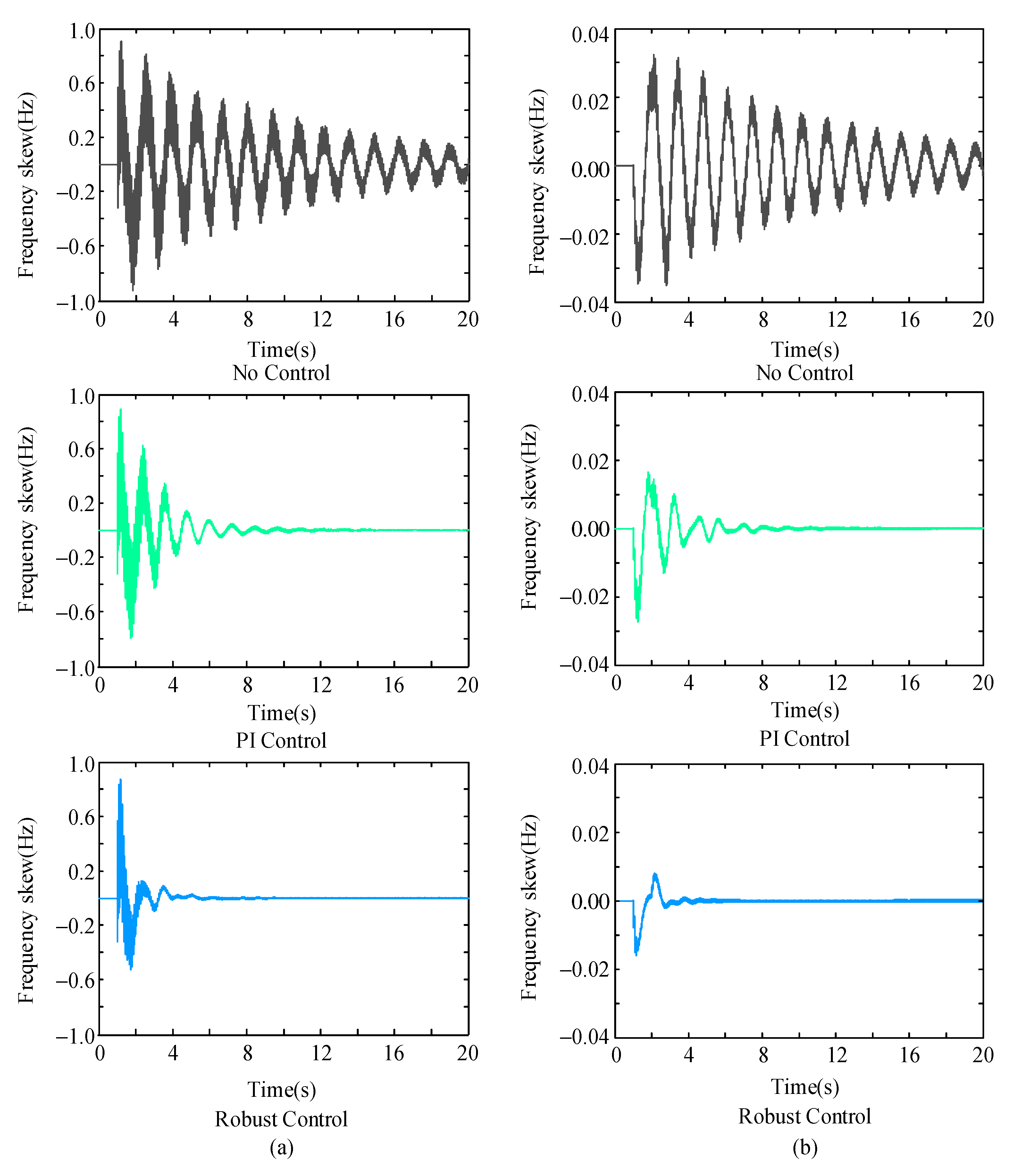
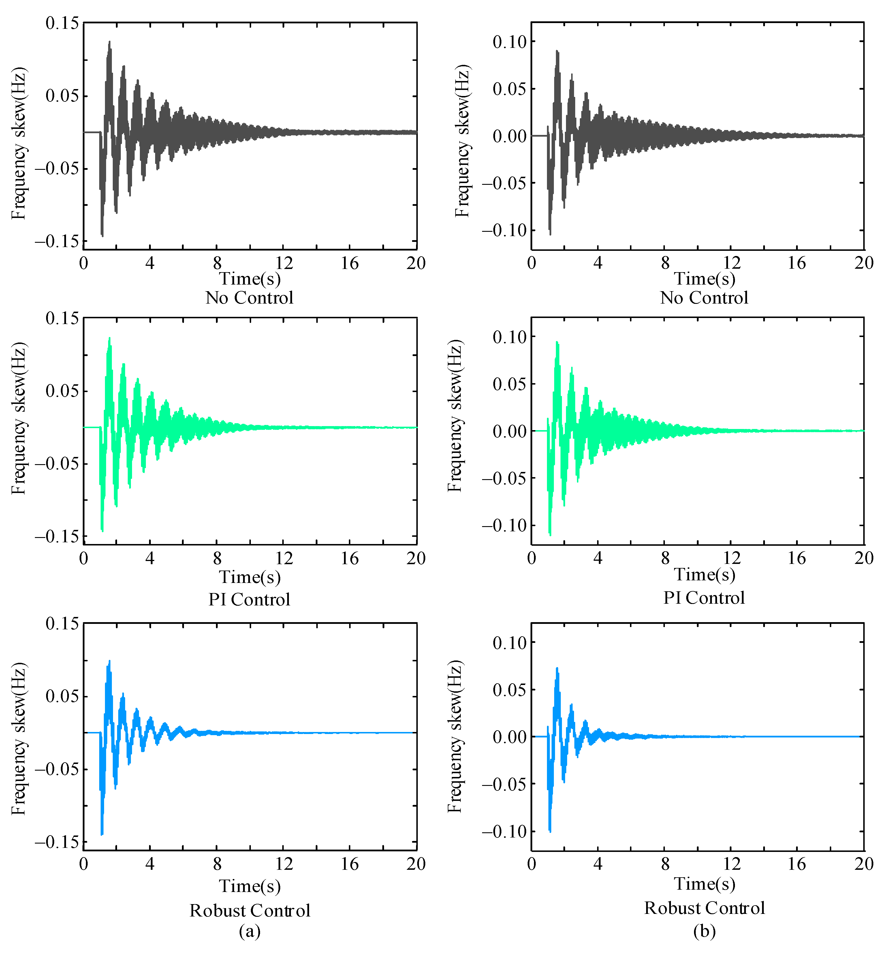
5. Simulation Verification

The conventional supplementary PI controller and the designed supplementary frequency robust controller, denoted as K1, are individually incorporated into the simulated islanded system model depicted in Figure 4. In PSCAD/EMTDC, various disturbances are introduced to simulate and validate the controller’s performance and robustness under different conditions.

5.1. Control Performance Verification

Disturbance 1: At the temporal juncture of t = 1 s, one of the dual-circuit AC pathways connecting Node A to Node C plunges into tumultuous disarray, succumbing to a three-phase short-circuit fault, an event of 0.1 s in temporal duration. When various supplementary controllers are deployed, the departure of the sending-end AC system’s frequency is illustrated, as depicted in Figure 9a.
Disturbance 2: At the appointed instant of t = 1 s, on the rectification side of the DC system, the electric current setpoint undergoes an ascent from 1.0 per unit to 1.05 per unit. When diverse supplementary controllers are employed, the sending-end AC system’s frequency deviation is portrayed, as delineated in Figure 9b.
The simulation results in Figure 9a demonstrate that when a severe three-phase short-circuit fault occurs in the AC system, the system’s frequency recovery is notably sluggish. The inclusion of supplementary frequency controllers effectively prevents frequency instability, enabling a rapid return to stability. Compared with a PI controller, the robust controller designed in this study exhibits stronger damping effects on frequency oscillations, resulting in reduced oscillation amplitude and faster frequency restoration to its steady-state value.
The simulated outcomes, as depicted in Figure 9b, lucidly demonstrate that when the DC system’s current setpoint is elevated by 0.05 per unit, the system’s frequency recovery is also sluggish. Similarly, the incorporation of supplementary frequency controllers effectively suppresses frequency oscillations, facilitating convergence to a stable frequency value. In contrast with a PI controller, the designed robust controller demonstrates excellent damping characteristics for both initial and subsequent frequency oscillations, leading to reduced oscillation amplitudes and faster stabilization.
From the simulation results in Figure 9, it is evident that the utilization of supplementary frequency robust controllers significantly enhances the system’s frequency stability. It has the capability to mitigate frequency fluctuations caused by various types of faults, surpassing the control efficacy of traditional supplementary PI controllers.
As Table 1 illustrates, PI control markedly shortens the adjustment time, while robust control demonstrates superior efficacy in preserving system stability and more effectively mitigating frequency oscillations.

5.2. Robustness Validation

Altering the operational mode of the islanded system, enabling the operation of hydroelectric plants A and B, transitioning the DC system from unipolar to bipolar operation, with a power transmission capacity of 3200 MW. Applying various disturbances for simulation to validate the robustness of the designed supplementary frequency robust controller.
Disturbance 3: At 1 s, a three-phase short-circuit fault occurs in one of the three circuits from node C to converter B, with a fault duration of 0.1 s. The variations in frequency deviation at the sending end of the AC system for different supplementary controllers are depicted in Figure 10a.
Disturbance 4: At 1 s, generator C in the thermal power plant ceases operation. The frequency deviation variations at the sending end of the AC system for different supplementary controllers are shown in Figure 10b.
The simulated results from Figure 10a,b reveal that, in the absence of any supplementary control measures, various types of faults induce persistent oscillations in the system’s frequency. Upon implementing the supplementary frequency robust controller, a remarkable enhancement in the system’s frequency stability ensues. Following a shift in the system’s operational mode, the efficacy of the traditional PI controller noticeably deteriorates, whereas the robust controller continues to effectively suppress the frequency oscillations provoked by various fault types, facilitating a swift and stable frequency convergence. This attests to the fact that the robust controller is less susceptible to the influence of systemic model inaccuracies and changes in the system’s operational mode, thus exhibiting greater robustness.
Table 2 indicates that, although PI control is capable of reducing the adjustment time, the duration for regulation is still excessively lengthy. In contrast, robust control significantly shortens the adjustment time, suppresses power oscillations, and rapidly reestablishes system stability.

5.3. Validation of Control Efficacy during Resilient Network Operation

The robust controller designed in this paper is specifically tailored for the system’s islanded operational mode; however, under normal circumstances, the system typically operates in a connected mode. Therefore, it is necessary to evaluate the performance of the robust controller under connected operation to determine whether it should remain active in non-islanded modes. By overlapping the dual-circuit 500 kV AC transmission lines connecting nodes A and C to the main grid, as shown in Figure 4, the system is transitioned back into a connected operational mode. Various perturbations are then applied in simulation to assess the control effectiveness of the supplementary frequency robust controller under connected operational conditions.
Disturbance 5: At 1 s, within the dual-circuit AC transmission lines connecting node A to node C, one of the circuits experiences a three-phase short-circuit fault lasting 0.1 s. Different supplementary controllers are configured, and the frequency deviation at the sending end of the AC system varies, as depicted in Figure 11a.
Disturbance 6: At 1 s, two generators in thermal power plant C cease operation. Different supplementary controllers are employed, and the frequency deviation at the sending end of the AC system fluctuates, as illustrated in Figure 11b.
From the simulation results presented in Figure 11, it is evident that during interconnected operation, the system inherently exhibits excellent frequency stability. Even in the event of a severe three-phase short-circuit fault, the frequency fluctuations remain relatively minor. After substantial changes to the system’s structure and operational mode, the effectiveness of the traditional PI controller diminishes significantly, nearly rendering it ineffective. However, the robust controller still exhibits a certain level of control effectiveness, expediting the system’s return to stability in terms of frequency. This serves as compelling evidence of the robust controller’s excellent resilience. Therefore, in non-islanding operational modes, the designed supplementary frequency robust controller can continue to operate, further enhancing the system’s frequency stability.
Table 3 reveals that PI control mitigates power oscillations induced by disturbances 3 and 4, albeit with a sluggish response and protracted adjustment period. Conversely, robust control swiftly curtails power fluctuations, facilitating a rapid restoration of system equilibrium. It is evident that robust control markedly surpasses traditional PI control in effectiveness.

6. Conclusions

In this paper, the utilization of a robust control method based on linear matrix inequalities is proposed. It can not only heighten the stability margin of the controller but also fortify its adaptability to the intricate and volatile real-world electrical power systems. Employing a regional pole placement approach has effectively averted the issue arising from uncertainties in the system, ensuring precise placement of dominant poles and guaranteeing exceptional dynamic and steady-state performance within the closed-loop system. Simulation results conducted in PSCAD/EMTDC underscore the capability of the HVDC supplementary frequency robust controller to significantly enhance the frequency stability of the islanded system. Its control effectiveness surpasses that of traditional supplementary PI controllers, showcasing superior robustness. This controller exhibits formidable resilience to uncertainties in the system model and maintains effective control across various fault scenarios in different operational modes, even during interconnected operations. The HVDC supplementary frequency robust controller devised in this study not only eliminates the trial-and-error approach to parameter tuning but also boasts simplicity, low order, superior performance, and ease of implementation. It holds substantial relevance for the practical design of supplementary frequency controllers in islanded systems.

Author Contributions

Conceptualization, C.X. and M.L.; methodology, M.L.; software, J.P.; validation, C.X., M.L. and J.P.; formal analysis, M.L.; investigation, C.X.; resources, M.L.; data curation, C.X.; writing—original draft preparation, Z.Z. and C.G.; writing—review and editing, M.L. and C.G.; visualization, Z.Z. and J.L.; supervision, Y.W.; project administration, S.G.; funding acquisition, Z.Z. All authors have read and agreed to the published version of the manuscript.

Funding

This work was partially supported by the National Natural Science Foundation of China (62101362, 52307127), the Project of State Key Laboratory of Power System Operation and Control (SKLD23KZ07), and the Fundamental Research Funds for the Central Universities (YJ202141, YJ202316).

Institutional Review Board Statement

Not applicable.

Informed Consent Statement

Not applicable.

Data Availability Statement

Data are contained within the article.

Conflicts of Interest

Author Chao Xing, Mingqun Liu and Junzhen Peng were employed by the company Electric Power Research Institute of Yunnan Power Grid Co., Ltd. The remaining authors declare that the research was conducted in the absence of any commercial or financial relationships that could be construed as a potential conflict of interest.

References

  1. Lopes, J.A.P.; Moreira, C.L.; Madureira, A.G. Defining control strategies for microgrids islanded operation. IEEE Trans. Power Syst. 2006, 21, 916–924. [Google Scholar] [CrossRef]
  2. Hong, C.; Wang, T.; Xiong, Q.; Zeng, Y. Fault recovery control for islanding operation of yunnan-guangdong UHVDC transmission system after mono-polar blocking. In Proceedings of the 2016 IEEE International Conference on Power System Technology (POWERCON), Wollongong, NSW, Australia, 28 September–1 October 2016; pp. 1–5. [Google Scholar] [CrossRef]
  3. McConnell, B. Applications of high temperature superconductors to DC electric power transmission and distribution. IEEE Trans. Appl. Supercond. 2005, 15, 2142–2145. [Google Scholar] [CrossRef]
  4. Inwumoh, J.; Baguley, C.A.; Gunawardane, K. A Fast and Accurate Fault Location Technique for High Voltage DC (HVDC) Systems Une technique rapide et précise de localisation des défauts pour les systèmes de courant continu à haute tension (CCHT). IEEE Can. J. Electr. Comput. Eng. 2022, 45, 383–393. [Google Scholar] [CrossRef]
  5. Zhang, G.; Cheng, Y.; Lu, N.; Guo, Q. Research of Hydro-Turbine Governor Supplementary Control Strategy for Islanding AC Grid at Sending Terminal of HVDC System. IEEE Trans. Energy Convers. 2016, 31, 1229–1238. [Google Scholar] [CrossRef]
  6. Kundur, P. Power System Stability and Control; McGraw-Hill: New York, NY, USA, 1994; Volume 17. [Google Scholar]
  7. Yang, L.; Wang, Y. Study on frequency oscillation controlling strategies for islanded operation mode of HVDC transmission systems. In Proceedings of the 12th IET International Conference on AC and DC Power Transmission (ACDC 2016), Beijing, China, 28–29 May 2016; pp. 1–6. [Google Scholar] [CrossRef]
  8. Rao, H.; Wu, W.; Mao, T.; Zhou, B.; Hong, C.; Liu, Y.; Wu, X. Frequency control at the power sending side for HVDC asynchronous interconnections between yunnan power grid and the rest of CSG. CSEE J. Power Energy Syst. 2021, 7, 105–113. [Google Scholar] [CrossRef]
  9. Huang, J.; Chen, Y.; Gao, Q.; Zhang, Y.; Yang, R.; Yang, R.; Diao, H. Research on HVDC frequency limit control to improve frequency restoration in muti-HVDC asynchronous system. In Proceedings of the 8th Renewable Power Generation Conference (RPG 2019), Shanghai, China, 24–25 October 2019; pp. 1–6. [Google Scholar] [CrossRef]
  10. Shi, H.; Chen, G.; Zhu, J.; Wang, Y.; Tai, K. FLC Dead band Optimization for HVDC System Stability Enhancement. In Proceedings of the 2020 IEEE Sustainable Power and Energy Conference (iSPEC), Chengdu, China, 23–25 November 2020; pp. 692–698. [Google Scholar] [CrossRef]
  11. Wang, L.; Thi, M.S.-N. Comparisons of Damping Controllers for Stability Enhancement of an Offshore Wind Farm Fed to an OMIB System Through an LCC-HVDC Link. IEEE Trans. Power Syst. 2013, 28, 1870–1878. [Google Scholar] [CrossRef]
  12. Zhang, H.; Wei, K.; Wei, Y.; Zhu, H. Emergency power control strategy of HVDC FLC based on modified SFR model in islanded HVDC sending system. Int. J. Electr. Power Energy Syst. 2022, 142, 108314. [Google Scholar] [CrossRef]
  13. Behera, A.; Panigrahi, T.K.; Ray, P.K.; Sahoo, A.K. A novel cascaded PID controller for automatic generation control analysis with renewable sources. IEEE/CAA J. Autom. Sin. 2019, 6, 1438–1451. [Google Scholar] [CrossRef]
  14. El-Ela, A.A.A.; El-Sehiemy, R.A.; Shaheen, A.M.; Diab, A.E.-G. Design of cascaded controller based on coyote optimizer for load frequency control in multi-area power systems with renewable sources. Control Eng. Pract. 2022, 121, 105058. [Google Scholar] [CrossRef]
  15. Ali, M.; Kotb, H.; Aboras, K.M.; Abbasy, N.H. Design of Cascaded PI-Fractional Order PID Controller for Improving the Frequency Response of Hybrid Microgrid System Using Gorilla Troops Optimizer. IEEE Access 2021, 9, 150715–150732. [Google Scholar] [CrossRef]
  16. Çelik, E. Design of new fractional order PI–fractional order PD cascade controller through dragonfly search algorithm for advanced load frequency control of power systems. Soft. Comput. 2021, 25, 1193–1217. [Google Scholar] [CrossRef]
  17. Li, C.; Deng, J.; Zhang, X.-P. Robust coordination damping control of multi-model system with FACTS devices via sequential approach. In Proceedings of the 11th IET International Conference on AC and DC Power Transmission, Birmingham, UK, 10–12 February 2015; pp. 1–6. [Google Scholar] [CrossRef]
  18. Li, Y.; Rehtanz, C.; Ruberg, S.; Luo, L.; Cao, Y. Wide-area robust coordination approach of HVDC and FACTS controllers for damping multiple interarea oscillations. IEEE Trans. Power Deliv. 2012, 27, 1096–1105. [Google Scholar] [CrossRef]
  19. Yang, F.; Gani, M.; Henrion, D. Fixed-Order Robust H Controller Design With Regional Pole Assignment. IEEE Trans. Autom. Control 2007, 52, 1959–1963. [Google Scholar] [CrossRef]
  20. Scherer, C.; Gahinet, P.; Chilali, M. Multiobjective output-feedback control via LMI optimization. IEEE Trans. Autom. Control 1997, 42, 896–911. [Google Scholar] [CrossRef]
  21. Pal, B.C.; Coonick, A.H.; Jaimoukha, I.M.; El-Zobaidi, H. A linear matrix inequality approach to robust damping control design in power systems with superconducting magnetic energy storage device. IEEE Trans. Power Syst. 2000, 15, 356–362. [Google Scholar] [CrossRef]
  22. Tripathy, P.; Srivastava, S.C.; Singh, S.N. A modified TLS-ESPRIT based method for low-frequency mode identification in power systems utilizing synchrophasor measurements. IEEE Trans. Power Syst. 2011, 26, 719–727. [Google Scholar] [CrossRef]
  23. Shen, L.; Song, R.; Xi, G. Simulation Research on Inhibition of Power System Oscillation Based on TLS-ESPRIT Method. In Proceedings of the 2021 International Conference on Advanced Electrical Equipment and Reliable Operation (AEERO), Beijing, China, 15–17 October 2021; pp. 1–5. [Google Scholar] [CrossRef]
  24. Zhang, Y.; Bose, A. Design of wide-area damping controllers for interarea oscillations. IEEE Trans. Power Syst. 2008, 23, 1136–1143. [Google Scholar] [CrossRef]
  25. Das, P.; Bhattacharjee, A.; Pathak, S. Performance analysis of TLS-Esprit and QR TLS- Esprit algorithm for Direction of Arrival estimation. In Proceedings of the 2015 International Conference on Communications and Signal Processing (ICCSP), Melmaruvathur, India, 2–4 April 2015; pp. 1395–1398. [Google Scholar] [CrossRef]
  26. Majumder, R.; Pal, B.C.; Chaudhuri, B.; Korba, P. Design and real time implementation of LMI based robust damping controllers for power systems. In Proceedings of the 2007 IEEE International Conference on System of Systems Engineering, San Antonio, TX, USA, 16–18 April 2007; pp. 1–7. [Google Scholar] [CrossRef]
  27. Pathak, D.; Sambariya, D. Methodologies for the Selection of Weighting Function. In Proceedings of the 2019 2nd International Conference on Power Energy, Environment and Intelligent Control (PEEIC), Greater Noida, India, 18–19 October 2019; pp. 347–350. [Google Scholar] [CrossRef]
  28. Wang, S.; Wang, Y.; Ma, J.; Wei, L.; Li, X.; Liu, X. Study of frequency and voltage characteristics of islanding HVDC system and the corresponding control strategy. In Proceedings of the 2014 International Conference on Power System Technology, Chengdu, China, 20–22 October 2014; pp. 2247–2251. [Google Scholar] [CrossRef]
Figure 1. Asynchronous interconnection system formed by LCC-HVDC connection with control system.
Electronics 13 00951 g001
Figure 2. Generalized control systems considering errors.
Electronics 13 00951 g002
Figure 3. Region D for pole location D = { s C : L + s U + s ¯ U T < 0 } .
Electronics 13 00951 g003
Figure 4. Simulation system structure of a real power system.
Electronics 13 00951 g004
Figure 5. The flow chart of transfer function identification.
Electronics 13 00951 g005
Figure 6. Diagram of robust controller.
Electronics 13 00951 g006
Figure 7. Bode diagrams of controller K and reduced-order controller K1.
Electronics 13 00951 g007
Figure 8. Diagram of PI controller.
Electronics 13 00951 g008
Figure 9. Diagram of system frequency difference before and after controller being added: (a) the first disturbance and (b) the second disturbance.
Electronics 13 00951 g009
Figure 10. Diagram of system frequency difference before and after controller being added: (a) the third disturbance and (b) the fourth disturbance.
Electronics 13 00951 g010
Figure 11. System frequency difference before and after controller being added: (a) the fifth disturbance and (b) the sixth disturbance.
Electronics 13 00951 g011
Table 1. Different control of the frequency deviation and the adjustment time constant of the oscillation frequency under disturbance 1 and 2.
No ControlPI ControlRobust Control
Disturbance 1>20 s10 s6 s
Disturbance 2>20 s10 s5 s
Disturbance 10.71 Hz0.81 Hz0.76 Hz
Disturbance 20.76 Hz0.81 Hz0.51 Hz
Table 2. Different control of the frequency deviation and the adjustment time constant of the oscillation frequency under disturbances 3 and 4.
No ControlPI ControlRobust Control
Disturbance 3>20 s>20 s6 s
Disturbance 4>20 s>20 s6 s
Disturbance 30.51 Hz0.61 Hz0.53 Hz
Disturbance 40.51 Hz0.51 Hz0.5 Hz
Table 3. Different control of the frequency deviation and the adjustment time constant of the oscillation frequency under disturbances 5 and 6.
No ControlPI ControlRobust Control
Disturbance 512 s10 s7 s
Disturbance 614 s12 s6 s
Disturbance 51.01 Hz0.98 Hz1.15 Hz
Disturbance 61.21 Hz1.25 Hz1.3 Hz
Disclaimer/Publisher’s Note: The statements, opinions and data contained in all publications are solely those of the individual author(s) and contributor(s) and not of MDPI and/or the editor(s). MDPI and/or the editor(s) disclaim responsibility for any injury to people or property resulting from any ideas, methods, instructions or products referred to in the content.

