Article

Sum-Rate Maximization Scheme for Multi-RIS-Assisted NOMA Uplink Systems

1
School of Information and Communication, Guilin University of Electronic Technology, Guilin 541004, China
2
School of Electronic Information and Automation, Guilin University of Aerospace Technology, Guilin 541004, China
*
Author to whom correspondence should be addressed.
Electronics 2024, 13(5), 969; https://doi.org/10.3390/electronics13050969
Submission received: 18 January 2024 / Revised: 22 February 2024 / Accepted: 28 February 2024 / Published: 3 March 2024
(This article belongs to the Special Issue Active or Passive Metasurface for Wireless Communications)

Abstract

:
Reconfigurable intelligent surface (RIS) and non-orthogonal multiple access (NOMA) are both highly promising technologies for future communication. Compared with traditional single-RIS-assisted NOMA systems, this paper considered multi-RIS-assisted NOMA uplink communication systems and proposed a sum-rate maximization scheme. At present, most research on RIS-assisted NOMA systems has not considered the joint optimization of users’ power, multi-RIS deployment, and multi-RIS phase shifts. Firstly, this paper proposed a sum-rate problem with multiple variates, which are involved in users’ power, multi-RIS deployments, and multi-RIS phase shifts. This problem is usually very complex and non-convex, which makes it very difficult to obtain an optimal solution. Then, the original problem was decomposed into three sub-problems through several derivations, which are relatively simple and easy to solve. Finally, the optimal multi-RIS deployment locations were obtained by a simulated annealing particle-swarm optimization algorithm, and a suboptimal solution based on positive semidefinite relaxation was adopted to solve the joint optimization problem of users’ power and multi-RIS phase shifts, respectively. The research results indicate that the sum-rate for the considered systems with the multi-RIS optimization algorithm can be improved by about 1 bps/Hz, compared with that of non-optimization, and under the same total number of RIS reflection units as a single-RIS scheme, the performance of the proposed scheme in this paper is superior to the single-RIS scheme, which proves the effectiveness of the proposed algorithm.

1. Introduction

In the future, wireless communication systems will need to meet increasingly demanding performance requirements from users, including higher speed, enhanced reliability, and broader coverage. This poses significant challenges for the design of future wireless communication systems. Recently, reconfigurable intelligent surfaces (RISs) have garnered considerable attention from both academia and industry due to their remarkable channel-regulation capabilities [1,2,3]. An RIS is a planar array composed of a large number of low-cost passive components that can regulate the phase and amplitude of the incident signal. Therefore, an RIS can enhance signals or suppress interference. Line-of-sight (LoS) communication can be established between base station (BS) and users by deploying RISs when the communication link between users and BS is blocked [4,5,6]. Due to their potential advantages, RISs have been combined with many existing wireless systems. For instance, in [7], an RIS is combined with an unmanned aerial vehicle network. An RIS is combined with multiuser MIMO Systems in [8]. In [9], an RIS is combined with device-to-device communications.
Apart from RIS, non-orthogonal multiple access (NOMA) is a promising future wireless communication technology that allows multiple users to transmit on the same frequency and time resources. NOMA achieves multi-user multiplexing in the power domain at the transmitter and multi-user signal separation based on successive interference cancellation (SIC) at the receiver, enabling non-orthogonal transmission among multiple users, which greatly improves the spectral efficiency and system throughput of the communication system [10,11,12]. This is particularly advantageous in scenarios where the demand for wireless connectivity is high and the spectrum is limited. Furthermore, NOMA offers the potential to enhance the quality of service for users by providing increased data rates and improved reliability [13]. The implementation of NOMA in wireless networks has the potential to revolutionize the way data are transmitted and received, paving the way for more-efficient and reliable communication systems.
The RIS-assisted NOMA(RIS–NOMA) communication systems are constructed by combining RIS with NOMA technology, which is a very promising scheme for improving the performance of communication systems [14,15,16]. To date, scholars have carried out a lot of research on RIS–NOMA communication systems. Reference [17] designed a simple and practical RIS–NOMA transmission scheme and studied the influence of finite-resolution RIS beamforming on a RIS–NOMA system. References [18,19] compare the theoretical performance of NOMA and orthogonal multiple access (OMA) in RIS-assisted downlink communication systems, and the results show that the NOMA scheme has higher energy efficiency than the OMA scheme in the RIS-assisted downlink communication systems. In order to maximize the sum-rate of RIS–NOMA uplink communication systems, reference [20] proposed a suboptimal solution based on positive semidefinite relaxation (SDR), which solved the joint optimization problem of users’ power and RIS phase shifts and obtained a higher sum-rate. One paper [21] proposed an algorithm based on the alternating direction multiplier method of second-order cone programming for the RIS–NOMA downlink multi-cluster communication network, which achieves higher performance gain than the SDR algorithm. Different from the above study, ref. [22] effectively improved the sum-rate of RIS–NOMA systems through deep-reinforcement learning technology. The authors of references [23,24] have studied the impact of multi-RIS on the performance of NOMA communication systems.
It is worth noting that there is not so much research on multi-RIS-assisted NOMA communication systems and the optimization of RIS deployment is not considered in the above research. The location of RIS deployment will significantly impact the system’s performance. Based on the above considerations, this paper firstly proposed an optimal multi-RIS deployment-location scheme using a simulated annealing particle-swarm optimization algorithm in multi-RIS-assisted NOMA uplink systems, and then a suboptimal solution based on positive semidefinite relaxation was adopted to solve the joint optimization problem of users’ power and multi-RIS phase shifts, respectively, which can effectively improve the sum-rate of the considered systems. Our main contributions are as follows:
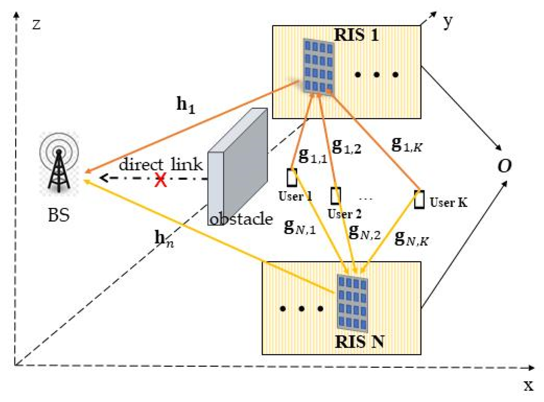
We propose a multi-RIS-assisted NOMA communication system, which considers the deployment optimization of multi-RIS.
This paper designs the sum-rate maximization problem of joint multi-RIS phase-shift matrix optimization, users’ power optimization, and multi-RIS deployment optimization, and the original problem is decomposed into three sub-problems.
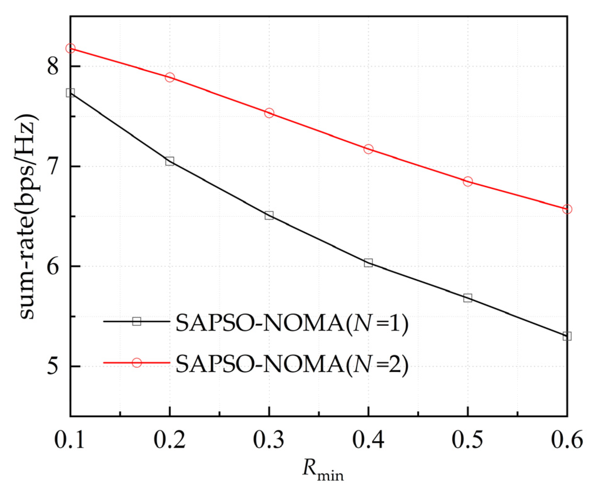
Using the proposed multi-RIS deployment optimization algorithm, the sum-rate of the system can effectively be improved by about 1 bps/Hz. In addition, compared with a single-RIS scheme and a time-division multiple-access (TDMA) scheme, the proposed multi-RIS–NOMA scheme can significantly improve the sum-rate of the system.
The rest of the paper is organized as follows: Section 2 describes the system model; Section 3 introduces problem formulation and describes the solving process of the formulated problem; simulation and numerical results are discussed in Section 4; and Section 5 concludes the paper.

2. System Model

Compared with the system that considered single-RIS-assisted NOMA systems in [20], this paper proposes a multi-RIS-assisted NOMA uplink system. As shown in Figure 1, the system consists of a single-antenna BS, N RISs equipped with M reflection units, and K users with a single antenna. In a similar paper [25], all RISs are equipped with a controller that can operate independently. There are assumed to be obstacles and no direct links between users and BSs; users establish a LoS link with BSs through RISs. In order to study the influence of RIS position on the sum-rate of the systems, it is assumed that in a 3D-cadier coordinate system, the position coordinates of the BS, user k ( k = 1 , , K ) , and the RIS n are represented by b = ( x b , y b , z b ) , u k = ( x k , y k , z k ) , and r n = ( x n , y n , z n ) , respectively. In order to consider the performance of the location for all RISs, all RISs are assumed to be deployed in the yellow area (O) in Figure 1. The location of RISs should meet the following conditions:
r n O   = ( x n , y n , z n ) | x n min x n x n max ,   y n min y n y n max , z n min z n z n max
where [ x n min , x n max ] , [ y n min , y n max ] and [ z n min , z n max ] represent the value range of the x-axis, y-axis, and z-axis coordinates of RIS n, respectively.
The distances between user k and RIS n and between RIS n and BS are denoted d n , k = u k r n 2 and d n = r n b 2 , respectively. The notation · 2 denotes the Euclidean norm. Since all RISs are deployed at a position with LoS to both the BS and users, the channels between the BS and the RIS and between the user and the RIS can be modeled as Rice channels. Therefore, the channel h n 1 × M between the RIS n and the BS and the channel g n , k M × 1 between the user k and the RIS n can be expressed as, respectively,
h n = d n α 1 / 2 κ 1 κ 1 + 1 h n L O S + 1 κ 1 + 1 h n N L O S
g n , k = d n , k α 2 / 2 κ 2 κ 2 + 1 g n , k L O S + 1 κ 2 + 1 g n , k N L O S
where α 1 , α 2 represent the corresponding path loss coefficients, κ 1 , κ 2 represent the Rice fading coefficients, and h n L O S , g n , k L O S , h n N L O S , g n , k N L O S represent the LoS component and the non-line-of-sight (NLoS) component of the corresponding path, respectively. Therefore, the received signal at the BS can be written as
y = k = 1 K n = 1 N h n Φ n g n , k p k s k + n 0
where p k represents the power and s k denotes the information symbol of user k satisfying E { | s k | 2 } = 1 . Φ n = d i a g ( θ n , 1 , θ n , 2 , , θ n , M ) is the phase-shift matrix of the RIS n, where θ n , m = e j φ n , m denotes the m-th element of RIS n and θ n , m = 1 , n 1 , 2 , , N , and m 1 , 2 , , M . n 0 C N ( 0 , σ 2 ) represents the additive white Gaussian noise (AWGN) at the BS.
From Equation (4), it can be seen that the signal of user k is subject to interference from other users. According to the principle of uplink NOMA, the BS performs continuous SIC to alleviate this interference, and the signals of users with better channel conditions are decoded earlier. Without loss of generality, it is assumed that the user equivalent channel gains are ordered by n = 1 N h n H Φ n g n , 1             n = 1 N h n H Φ n g n , K .
The signal-to-interference-plus-noise ratio of user k at BS after SIC can be written as
γ k = n = 1 N h n H Φ n g n , k 2 p k i = k + 1 K n = 1 N h n H Φ n g n , i 2 p i + σ 2
where variable i = k + 1 K n = 1 N h n H Φ n g n , i 2 p i denotes the inter-user interference after SIC. i = k + 1 K n = 1 N h n H Φ n g n , i 2 p i when k = K . Then, according to Equation (5), the communication rate for user k obtained is given by
R k = log 2 ( 1 + γ k )

3. Problem Formulation and Joint Optimization

3.1. Problem Formulation

This paper aims to maximize the sum-rate of RIS–NOMA by optimizing the multi-RIS location, multi-RIS phase shift, and user power under the user quality-of-service (QoS). Therefore, the sum-rate maximization problem of the systems can be expressed as
P ( 1 ) : max P , Φ , r k = 1 K R k
s . t .   P k P k max , k { 1 , , K }
R k R k min , k { 1 , , K }
θ n , m = 1 , n { 1 , , N } , m { 1 , , M }
  r n O , n { 1 , , N }
where P = [ p 1 , p 2 , , p K ] denotes the users’ power vector, Φ = [ Φ 1 , , Φ N ] denotes the phase-shift matrix of all RISs, and r = [ r 1 , , r N ] denotes the position of all RISs. Equation (7b) denotes the maximum transmit power of the users, Equation (7c) denotes the QoS of the users, Equation (7d) denotes the mode of the phase-shift element of the RISs, and Equation (7e) denotes the deployment area of the RISs. Due to the complexity of the objective problem expression of P(1) and the high degree of coupling between multiple variables, P(1) is non-convex, and it is difficult to obtain the optimal solution directly for each variable. According to the results in [26], the non-convex objective problem P(1) can be decomposed into three sub-problems for solving multi-RIS phase-shift optimization, users’ power optimization and multi-RIS deployment optimization.

3.2. Optimization of Three Sub-Problems

Firstly, after some derivations of (7a), we can obtain the following theorem.
Theorem 1.
The sum-rate of the RIS–NOMA can be expressed as
R sum = k = 1 K R k = k = 1 K log 2 n = 1 N h n H Φ n g n , k 2 p k i = k + 1 K n = 1 N h n H Φ n g n , i 2 p i + σ 2 = log 2 1 + k = 1 K n = 1 N h n H Φ n g n , k 2 p k σ 2 .
Proof. 
Please see Appendix A. □
From Equation (8), the sum-rate of the system is independent of the decoding order of SIC, and it is only related to the variable k = 1 K n = 1 N h n H Φ n g n , k 2 p k . Therefore, problem P(1) can be equivalent to the following problem, P(2):
P ( 2 ) : max P , Φ , r           k = 1 K n = 1 N h n H Φ n g n , k 2 p k s . t . ( 7 b ) , ( 7 c ) , ( 7 d ) , ( 7 e )
Next, we decompose problem P(2) into three sub-problems, which are multi-RIS phase-shift optimization, users’ power optimization, and multi-RIS deployment optimization, respectively.

3.2.1. Multi-RIS Phase-Shift Optimization Based on SDR

With the determined users’ power as well as multi-RIS locations, problem P(2) concerning the multi-RIS phase-shift optimization sub-problem can be written as
P ( 3 ) : max Φ           k = 1 K n = 1 N h n H Φ n g n , k 2 p k s . t . ( 7 c ) , ( 7 d )
In order to solve problem P(3) more efficiently, the diagonal matrix Φ n is rearranged into the vector θ n = [ θ n , 1 , θ n , 2 , , θ n , M ] T M × 1 and an auxiliary variable u n , k = d i a g ( h n H ) g n , k M × 1 is introduced, and we can obtain the following expression
k = 1 K n = 1 N h n H Φ n g n , k 2 p k = k = 1 K n = 1 N θ n H u n , k 2 p k
Equation (11) remains complex and unfavorable for the solution. We introduce two auxiliary variables w = [ θ 1 T , , θ N T ] T M t o l × 1 and U k = [ u 1 , k T , u N , k T ] T M t o l × 1 , where M t o t a l = N × M denotes the sum of the elements of all RISs. Equation (11) can be rewritten as
k = 1 K n = 1 N θ n H u n , k 2 p k = k = 1 K w H U k 2 p k = k = 1 K w H U k U k H w p k
Let A = k = 1 K U k U k H p k , and Problem P(3) can be rewritten as
P ( 4 ) :   max w   w H A w
s . t .   |     w H U k |     2 p k i = k + 1 K w H U i 2 p i + σ 2 ( 2 R k min 1 ) ,   k { 1 , , K }
w i = 1 i { 1 , , N × M }
We now focus on solving problem P(4). Based on the nature of the matrix trace, the following expression can be obtained
w H A w = Tr ( w H A w ) = Tr ( A w w H )
where Tr ( · ) denotes the trace of a matrix. We define W = w w H , where W 0 and rank ( W ) = 1 . Since the rank-one constraint is non-convex, we relax this constraint by using SDR, and problem P(4) can be transformed into
P ( 5 ) :   max W   Tr ( A W )
s . t .   Tr ( U ¯ k W ) ( 2 R k min 1 )   i = k + 1 K Tr ( U ¯ i W ) + σ 2 k { 1 , , K }
W 0
W i , i = 1   i { 1 , , N × M }
where U ¯ i = U i U i H p i , W i , i represents the i-th element of the main diagonal of the semi-positive definite matrix W . Problem P(5) is a standard semidefinite programming problem that can be solved using the MATLAB R2021b CVX toolbox. However, it is usually difficult to obtain a solution that satisfies the rank-one constraint, i.e., rank ( W ) 1 . A solution that satisfies the condition can be obtained by using Gaussian randomization for correction [27].

3.2.2. Optimization of Users’ Power

For the given multi-RIS deployment location and phase-shift matrix Φ , the sub-problem of problem P(2) regarding the users’ power vector P can be expressed as
P ( 6 ) : max P k = 1 K n = 1 N h n H Φ n g n , k 2 p k s . t .   P k P k max , k { 1 , , K }   Tr ( U ¯ k W ) ( 2 R k min 1 ) ( q = k + 1 K Tr ( U ¯ q W ) + σ 2 )   k { 1 , , K }
Problem P(6) is a linear programming problem that can be solved using the MATLAB convex optimization tool (CVX) to obtain the optimal solution for users’ power vector P.

3.2.3. Multi-RIS Deployment Algorithm Based on SAPSO

After finishing the above two parts in Section 3.2.2 and Section 3.2.3, we can obtain the following
P ( 7 ) :   max r R sum        
s . t .   r n O , n { 1 , , N }
The optimization for multi-RIS deployment location is very exhaustive, and the simulated annealing particle-swarm optimization (SAPSO) algorithm has strong optimization ability and good convergence and robustness [28,29,30]. Therefore, the multi-RIS deployment locations in the paper are obtained based on the SAPSO algorithm.
In the SAPSO algorithm, each particle has two components: position x i and velocity v i   , which are expressed as x i = [ x i , 1 , x i , 2 , , x i , 3 N ] and v i = [ v i , 1 , v i , 2 , , v i , 3 N ] , respectively. The position x i and velocity v i   of particle i are updated, respectively, by the following equation
v i   t + 1 = ω     v i   t + c 1 ζ 1 ( p id x i t ) + c 2 ζ 2 ( g b e s t x   i t )
x i t + 1 = x i t + v i t + 1
where i = 1 , 2 ,         , m , in which m denotes the total number of particles in the population, t is the number of iterations, ζ 1 and ζ 2 are a random number of sizes between [0, 1], p id denotes the individual optimal solution location, g b e s t denotes the population optimal solution location, c 1 and c 2 are the learning factors, v i [ v min , v max ] , and v min and v max represent the minimum and maximum velocity of the particles, respectively. ω   are the inertia weighting coefficients and are updated according to the following equation
ω = ω max ( ω max ω min ) t / t max
c 1 = c 2 = η × exp ( T t / T 0 ) × rand ( 0 , 1 )
where t max is the maximum number of iterations, and as the number of iterations increases, the size of ω will decrease linearly from ω max to ω min . Then, rand(0,1) is a random number between 0 and 1, cognitive coefficient η = 2, T 0 is the initial temperature of simulated annealing, and T is the temperature of simulated annealing.
Due to the difficulty in obtaining the exact expression of R sum in problem P(7), we use the upper bounds C u p of the sum-rate for systems as our optimization objective function values. The upper bounds C u p is obtained through the following steps: Firstly, under the constraint of (17b), we set the position of RIS n to r n = ( x i , 1 + 3 ( 3 n 1 ) , x i , 2 + 3 ( 3 n 1 ) , x i , 3 + 3 ( 3 n 1 ) ) , randomly generate users’ positions in a certain area, and set the power of all users to the maximum transmission power. Then, according to paper [8], C u p = log 2 ( 1 + λ M total 2 / σ 2 ) , where λ represents the maximum eigenvalue of A . Finally, due to the influence of random channels and the random distribution of users, C u p is the mean value obtained by q = 2000 Monte Carlo simulations. Let particle i at position x i = r = [ r 1 , , r N ] represent the position of all RISs, and let C u p ( x i ) represent the upper bounds of the system for particles at position x i . The detailed steps based on the SAPSO algorithm are described in Algorithm 1.
After obtaining the optimal deployment locations for multiple RISs through Algorithm 1, problems P(5) and P(6) are solved in turn according to Equations (15) and (16). Subsequently, the suboptimal solution for the original problem P(1) can be obtained.
Algorithm 1 The algorithm based on SAPSO to solve P(7)
Initialize: particle population number m, maximum inertia weight ω max , minimum inertia weight ω min , maximum number of iterations t max , initial annealing temperature T 0 , initial temperature T , cooling coefficient a , velocity and position of all particles, Individual extreme position P id , individual extreme P i b e s t , global optimum position g b e s t , global optimum G b e s t .
Iteration:
 1: while  t > t max  do
 2: for  i = 1 : m  do
 3:  Calculate C = C u p ( x i t ) P i b e s t ;
 4:  if  C > 0  then
 5:    Set P i d = x i t , P i b e s t = C u p ( x i t ) ;
 6:    else if  exp ( C / T t ) > rand ( 0 , 1 )  then
 7:     Set P i d = x i t , P i b e s t = C u p ( x i t ) ;
 8:     Update c 1 , c 2 by Equation (21);
 9:    end elseif
10:  end if
11:  if  P i b e s t > G best  then
12:    Set g b e s t = P i d , G b e s t = P i b e s t ;
13:  end if
14:  Update ω   by Equation (20);
15:  Update v i t + 1 , x i t + 1 by Equation (18) and Equation (19), respectively;
16:  Set T t + 1 = a T t ;
17: end for
18:  Set t = t + 1;
19: end while
20: output: The multi-RIS deployment locations g b e s t

3.3. Complexity Analysis

In this paper, the multi-RIS phase-shift matrix is solved based on SDR; its complexity is O ( N M ) 3.5 + I max ( N M ) 3 , where I max represents the number of iterations required for Gaussian randomization correction [31]. Problem P(6) is solved by the CVX toolbox, and its complexity is O ( K 3.5 ) [31]. We obtain the multi-RIS deployment locations through Algorithm 1, with a complexity of O t max ( m Q ( N M ) 3 ) . In summary, the overall complexity of our scheme is O K 3.5 + t ( m Q ( N M ) 3 ) + ( N M ) 3.5 + I max ( N M ) 3 . It is important to note that once the algorithm based on SAPSO is used to determine the optimal deployment location for multiple RISs within a user activity area, all RIS positions become fixed. Therefore, during subsequent system operations, the total complexity of the proposed scheme becomes O K 3.5 + ( N M ) 3.5 + I max ( N M ) 3 .

4. Simulation Result

In this section, the sum-rate of the multi-RIS-assisted uplink NOMA communication system is simulated, and Monte Carlo simulations are performed 2000 times without any special description. The simulation parameters of the system are set as follows: path loss coefficient α 1 = 2 , α 2 = 2.6 , Rice fading coefficients κ 1 = κ 2 = 5 dB, the maximum transmit power for all users is set to P max = 10   dBm , the QoS is set to R k min = R min , and noise variance σ 2 = 60   dBm .
Firstly, we simulated the multi-RIS deployment location using Algorithm 1. The simulation parameters for Algorithm 1 are set as follows: ω max = 0.9 , ω min = 0.4 , particle population number m = 30 , cooling coefficient a = 0.98 a = 30 , initial c 1 = c 2 = 1.5 , initial annealing temperature T 0 = 100 , and maximum number of iterations t max = 200 . In order to make a fair comparison between the single-RIS scheme and the multi-RIS scheme, we assume that the number of total RIS reflective elements in the different schemes is M total , and that the number of reflective elements in each RIS is M = M total / N . As shown in Figure 2, the BS is deployed at (0,60,20), we assume that K users are randomly distributed in a rectangular area of 80   ×   120   m , and the heights of the users are all set to zero. RIS 1 and RIS 2 are deployed in Region 1 and Region 2, respectively. After running Algorithm 1, we obtained the specific coordinates of RIS 1 and RIS 2 as (88,120,20) and (86,0,20). For comparison, we considered another baseline scheme where the coordinates of RIS1 and RIS2 are randomly generated within Region 1 and Region 2, respectively, and we named the scheme Random.
Figure 3 provides the convergence performance in the proposed Algorithm 1. The other parameters of the Random scheme are the same as in Algorithm 1. In Figure 3, we can see that the sum-rate of the system tends to be stable after nearly 40 iterations of Algorithm 1, which indicates that the proposed Algorithm 1 has good convergence properties.
Figure 4 shows the variation of the sum rate with the total RIS element M total under different schemes. In this simulation, in order to reflect the advantages of the NOMA scheme, we compared the TDMA scheme in paper [32] with the proposed NOMA scheme. The RIS deployment location for the single-RIS scheme (N = 1) is obtained by Algorithm 1 as (85,120,20). In Figure 4, it can be clearly seen that the sum-rate of each scheme increases with the increase in total RIS reflection elements. The reason is that the RIS can adjust the phase shift of the incident signal. With the increase in total RIS reflection elements, the RIS has higher spatial degrees of freedom and can optimize the phase shift more flexibly. In addition, the sum rate of the NOMA scheme is always better than that of the TDMA scheme, which proves the superiority of NOMA.
Figure 5 further shows the sum-rate versus the number of users under the different schemes. In this simulation, we obtained the specific coordinates of RIS 3 and RIS 4 as (84,120,20) and (97,0,20). In Figure 5, we can see that the sum-rate of all multi-RIS schemes increases with the increase in the number of users k. However, all the single-RIS schemes (N = 1) show a decreasing trend when k > 4. The reason behind this phenomenon is the “multiplicative fading” effect introduced by the RIS [33]. The multi-RIS scheme can alleviate this effect to a certain extent. At the same time, we can observe that the sum-rate of SAPSO–NOMA(N = 4) is about 1 bps/Hz higher than the Random–NOMA(N = 4), This proves the effectiveness of our proposed Algorithm 1. At the same time, we can also see that due to the limitation of the total number of RIS units M, the difference in the sum- rate between SAPSO–NOMA (N = 2) and SAPSO–NOMA (N = 4) is not large. Therefore, only two RIS units can be used in practical applications to reduce the complexity of the system.
As shown in Figure 6, we further studied the impact of the QoS R min on the single-RIS scheme and the proposed scheme. With the increase in QoS R min , the sum-rate of the systems of the two schemes continues to decline, and the rate of decline in our scheme is slower. It is clear that the proposed scheme is always superior to the single-RIS scheme. Comparing Figure 5 with Figure 6, we can observe that multi-RIS-assisted NOMA scheme has a more significant sum-rate gain when there are more users or a higher QoS. The reason can also be explained by the “multiple fading” effect. By deploying multi-RIS, edge users can have at least one closer RIS to serve them.

5. Conclusions

The paper investigates sum-rate maximization in the RIS–NOMA uplink system, which is formulated by jointly optimizing the deployment of multi-RIS, the phase shift of multi-RIS, and users’ transmit power. We transformed the original problem into three sub-problems and solved them accordingly using the SDR algorithm and SAPSO algorithm. The simulation results show that the sum-rate maximization scheme of the multi-RIS-assisted NOMA uplink system is superior to the single-RIS scheme and the TDMA scheme, and the SAPSO algorithm can effectively improve the sum-rate of the system compared with random deployment. In addition, we find that multi-RIS schemes can achieve more significant sum-rate gains when there are more users or a higher QoS.

6. Future Research

According to Section 2 and Section 3, it is very important to develop imperfect CSI schemes, which can improve the robustness of the system. It is also important to study the system performance under imperfect SIC. Moreover, our work can be easily extended to active multi-RIS, and it can effectively overcome “multiplicative fading”.

Author Contributions

Conceptualization, J.J.; methodology, D.Q.; software, D.Q.; validation, D.Q.; data curation, D.Q.; writing—original draft preparation, D.Q.; writing—review and editing, D.Q. and J.J.; supervision, D.Q. and J.J.; project administration, D.Q. and J.J.; funding acquisition, D.Q. and J.J. All authors have read and agreed to the published version of the manuscript.

Funding

This research was funded by the National Natural Science Foundation of China (no. 61650103).

Data Availability Statement

Data are contained within the article.

Conflicts of Interest

The authors declare no conflicts of interest.

Abbreviations

The following abbreviations are used in this manuscript:
BSBase station
NOMANon-orthogonal multiple access
TDMATime division multiple access
OMAOrthogonal multiple access
RISReconfigurable intelligent surface
LOSLine-of-sight
NLOSNon-line-of-sight
AWGNAdditive white Gaussian noise
SICSuccessive interference cancelation
QoSQuality-of-service

Appendix A

The proof of Equation (8) is as follows
R s u m = k = 1 K R k = k = 1 K log 2 1 + n = 1 N h n H Φ n g n , k 2 p k i = k + 1 K n = 1 N h n H Φ n g n , i 2 p i + σ 2   = k = 1 K log 2 n = 1 N h n H Φ n g n , k 2 p k + i = k + 1 K n = 1 N h n H Φ n g n , i 2 p i + σ 2 i = k + 1 K n = 1 N h n H Φ n g n , i 2 p i + σ 2 = log 2 n = 1 N h n H Φ n g n , 1 2 p 1 + k = 2 K n = 1 N h n H Φ n g n , k 2 p k + σ 2 k = 2 K n = 1 N h n H Φ n g n , k 2 p k + σ 2 × n = 1 N h n H Φ n g n , 2 2 p 2 + k = 3 K n = 1 N h n H Φ n g n , k 2 p k + σ 2 k = 3 K n = 1 N h n H Φ n g n , k 2 p k + σ 2 × × n = 1 N h n H Φ n g n , K 2 p K + k = K + 1 K n = 1 N h n H Φ n g n , k 2 p k + σ 2 k = K + 1 K n = 1 N h n H Φ n g n , k 2 p k + σ 2 = log 2 k = 1 K n = 1 N h n H Φ n g n , k 2 p k + σ 2 i = 2 K n = 1 N h n H Φ n g n , i 2 p i + σ 2 × k = 2 K n = 1 N h n H Φ n g n , k 2 p k + σ 2 k = 3 K n = 1 N h n H Φ n g n , k 2 p k + σ 2 × × k = K 1 K n = 1 N h n H Φ n g n , k 2 p i + σ 2 k = K K n = 1 N h n H Φ n g n , k 2 p k + σ 2 × k = K K n = 1 N h n H Φ n g n , k 2 p k + σ 2 σ 2 = log 2 1 + k = 1 K n = 1 N h n H Φ n g n , k 2 p k σ 2
where k = K + 1 K n = 1 N h n H Φ n g n , k 2 p k when k = K. This means that user K is not disturbed by other users.

References

  1. Huang, C.; Hu, S.; Alexandropoulos, G.C.; Zappone, A.; Yuen, C.; Zhang, R.; Renzo, M.D. Holographic MIMO Surfaces for 6G Wireless Networks: Opportunities, Challenges, and Trends. IEEE Wirel. Commun. 2020, 27, 118–125. [Google Scholar] [CrossRef]
  2. Wu, Q.; Zhang, R. Towards Smart and Reconfigurable Environment: Intelligent Reflecting Surface Aided Wireless Network. IEEE Commun. Mag. 2020, 58, 106–112. [Google Scholar] [CrossRef]
  3. Wu, Q.; Zhang, R. Beamforming Optimization for Wireless Network Aided by Intelligent Reflecting Surface with Discrete Phase Shifts. IEEE Trans. Commun. 2020, 68, 1838–1851. [Google Scholar] [CrossRef]
  4. Zheng, B.; You, C.; Zhang, R. Double-IRS Assisted Multi-User MIMO: Cooperative Passive Beamforming Design. IEEE Trans. Commun. 2021, 20, 4513–4526. [Google Scholar] [CrossRef]
  5. Pei, X.; Yin, H.; Tan, L.; Cao, L.; Li, Z.; Wang, K.; Zhang, K.; Björnson, E. RIS-Aided Wireless Communications: Prototyping, Adaptive Beamforming, and Indoor/Outdoor Field Trials. IEEE Trans. Commun. 2021, 69, 8627–8640. [Google Scholar] [CrossRef]
  6. Zheng, Z.; You, C.; Mei, W.; Zhang, R. A Survey on Channel Estimation and Practical Passive Beamforming Design for Intelligent Reflecting Surface Aided Wireless Communications. IEEE Commun. Surv. Tutor. 2022, 24, 1035–1071. [Google Scholar] [CrossRef]
  7. Zhou, X.; Wu, Q.; Yan, S.; Shu, F.; Li, J. UAV-Enabled Secure Communications: Joint Trajectory and Transmit Power Optimization. IEEE Trans. Veh. Technol. 2019, 68, 4069–4073. [Google Scholar] [CrossRef]
  8. Yan, W.; Yuan, X.; He, Q.; Kuai, X. Passive Beamforming and Information Transfer Design for Reconfigurable Intelligent Surfaces Aided Multiuser MIMO Systems. IEEE J. Sel. Areas Commun. 2020, 38, 1793–1808. [Google Scholar] [CrossRef]
  9. Chen, Y.; Ai, B.; Zhang, H.; Niu, Y.; Song, L.; Han, Z.; Poor, H. Reconfigurable Intelligent Surface Assisted Device-to-Device Communications. IEEE Trans. Wirel. Commun. 2021, 20, 2792–2804. [Google Scholar] [CrossRef]
  10. Shi, Z.; Zhang, C.; Fu, Y.; Wang, H.; Yang, G.; Ma, S. Achievable diversity order of HARQ-aided downlink NOMA systems. IEEE Trans. Veh. Technol. 2020, 69, 471–487. [Google Scholar] [CrossRef]
  11. Khan, A.; Usman, M.A.; Usman, M.R.; Ahmad, M.; Shin, S.-Y. Link and System-Level NOMA Simulator: The Reproducibility of Research. Electronics 2021, 10, 2388. [Google Scholar] [CrossRef]
  12. Marques da Silva, M.; Dinis, R.; Martins, G. On the Performance of LDPC-Coded Massive MIMO Schemes with Power-Ordered NOMA Techniques. Appl. Sci. 2021, 11, 8684. [Google Scholar] [CrossRef]
  13. Liu, Y.; Qin, Z.; Elkashlan, M.; Ding, Z.; Nallanathan, A.; Hanzo, L. Non-orthogonal multiple access for 5G and beyond. Proc. IEEE 2017, 105, 2347–2381. [Google Scholar] [CrossRef]
  14. Pan, C.; Ren, H.; Wang, K.; Kolb, J.F.; Elkashlan, M.; Chen, M.; Renzo, M.D.; Hao, Y.; Wang, J.; Swindlehurst, A.; et al. Reconfigurable Intelligent Surfaces for 6G Systems: Principles, Applications, and Research Directions. IEEE Commun. Mag. 2021, 59, 14–20. [Google Scholar] [CrossRef]
  15. Ding, Z.; Lv, L.; Fang, F.; Dobre, O.A.; Karagiannidis, G.K.; Al-Dhahir, N.; Schober, R.; Poor, H. A State-of-the-Art Survey on Reconfigurable Intelligent Surface-Assisted Non-Orthogonal Multiple Access Networks. Proc. IEEE 2022, 110, 1358–1379. [Google Scholar] [CrossRef]
  16. Maraqa, O.; Rajasekaran, S.; Al-Ahmadi, S.; Yanikomeroglu, H.; Sait, S.M. A Survey of Rate-Optimal Power Domain NOMA with Enabling Technologies of Future Wireless Networks. IEEE Commun. Surv. Tutor. 2020, 22, 2192–2235. [Google Scholar] [CrossRef]
  17. Ding, Z.; Poor, H.V. A Simple Design of IRS-NOMA Transmission. IEEE Commun. Lett. 2020, 24, 1119–1123. [Google Scholar] [CrossRef]
  18. Zheng, B.; Wu, Q.; Zhang, R. Intelligent Reflecting Surface-Assisted Multiple Access with User Pairing: NOMA or OMA? IEEE Commun. Lett. 2020, 24, 753–757. [Google Scholar] [CrossRef]
  19. Yue, X.; Liu, Y. Performance Analysis of Intelligent Reflecting Surface Assisted NOMA Networks. IEEE Trans. Wirel. Commun. 2022, 21, 2623–2636. [Google Scholar] [CrossRef]
  20. Zeng, M.; Li, X.; Li, G.; Hao, W.; Dobre, A.D. Sum-rate Maximization for IRS-Assisted Uplink NOMA. IEEE Commun. Lett. 2021, 25, 234–238. [Google Scholar] [CrossRef]
  21. Li, Y.; Jiang, M.; Zhang, Q.; Qin, J. Joint Beamforming Design in Multi-Cluster MISO NOMA Reconfigurable Intelligent Surface-Aided Downlink Communication Networks. IEEE Trans. Commun. 2021, 69, 664–674. [Google Scholar] [CrossRef]
  22. Shehab, M.; Ciftler, B.S.; Khattab, T.; Abdallah, M.M.; Trinchero, D. Deep Reinforcement Learning Powered IRS-Assisted Downlink NOMA. IEEE Open J. Commun. Soc. 2022, 3, 729–739. [Google Scholar] [CrossRef]
  23. Chen, D.; Yao, J.; Lin, Y.; Li, Y.; Zhang, H. Research on Coverage Enhancement and Sum-rate Maximization of 5G NOMA Network Based on Multiple IRSs. In Proceedings of the 2022 IEEE 5th Advanced Information Management, Communicates, Electronic and Automation Control Conference (IMCEC), Chongqing, China, 16–18 December 2022; pp. 1349–1354. [Google Scholar]
  24. Yang, Z.; Chen, M.; Saad, W.; Xu, W.; Shikh-Bahaei, M.; Poor, H.V.; Cui, S. Energy-Efficient Wireless Communications with Distributed Reconfigurable Intelligent Surfaces. IEEE Trans. Wirel. Commun. 2022, 21, 665–679. [Google Scholar] [CrossRef]
  25. Do, T.N.; Kaddoum, G.; Nguyen, T.L.; da Costa, D.B.; Haas, Z.J. Multi-RIS-Aided Wireless Systems: Statistical Characterization and Performance Analysis. IEEE Trans. Commun. 2021, 69, 8641–8658. [Google Scholar] [CrossRef]
  26. Mu, X.; Liu, Y.; Guo, L.; Lin, J.; Poor, H.V. Intelligent Reflecting Surface Enhanced Multi-UAV NOMA Networks. IEEE J. Sel. Areas Commun. 2021, 39, 3051–3066. [Google Scholar] [CrossRef]
  27. Wu, Q.; Zhang, R. Intelligent Reflecting Surface Enhanced Wireless Network: Joint Active and Passive Beamforming Design. In Proceedings of the 2018 IEEE Global Communications Conference (GLOBECOM), Abu Dhabi, United Arab Emirates, 9–13 December 2018; pp. 1–6. [Google Scholar]
  28. Ji, Q.; Chen, Q.; Song, C. Improved Particle Swarm Optimization Geomagnetic Matching Algorithm Based on Simulated Annealing. IEEE Access. 2020, 8, 226064–226073. [Google Scholar] [CrossRef]
  29. Li, C.; You, F.; Yao, T.; Wang, J.; Shi, W.; Peng, J.; He, S. Simulated Annealing Particle Swarm Optimization for High-Efficiency Power Amplifier Design. IEEE Trans. Microw. Theory Tech. 2021, 69, 2494–2505. [Google Scholar] [CrossRef]
  30. Zhou, T.; Sun, W. Optimization of Battery–Supercapacitor Hybrid Energy Storage Station in Wind/Solar Generation System. IEEE Trans. Sustain. Energy 2014, 5, 408–415. [Google Scholar] [CrossRef]
  31. Luo, Z.; Ma, W.; So, A.M.; Ye, Y.; Zhang, S. Semidefinite relaxation of quadratic optimization problems. IEEE Signal Process. Mag. 2010, 27, 20–34. [Google Scholar] [CrossRef]
  32. Mu, X.; Liu, Y.; Guo, L.; Lin, J.; Schober, R. Joint Deployment and Multiple Access Design for Intelligent Reflecting Surface Assisted Networks. IEEE Trans. Wirel. Commun. 2021, 20, 6648–6664. [Google Scholar] [CrossRef]
  33. Zhang, Z.; Dai, L.; Chen, X.; Liu, C.; Yang, F.; Schober, R.; Poor, H.V. Active RIS vs. Passive RIS: Which Will Prevail in 6G? IEEE Trans. Commun. 2023, 71, 1707–1725. [Google Scholar] [CrossRef]
Figure 1. System model.
Electronics 13 00969 g001
Figure 2. Simulation setup for the RIS–NOMA system (top view).
Electronics 13 00969 g002
Figure 3. Iterative convergence rate of Algorithm 1.
Electronics 13 00969 g003
Figure 4. Sum-rate versus the total RIS reflective elements M total under the different schemes when K = 5, R min = 0.2 bps/Hz.
Electronics 13 00969 g004
Figure 5. Sum rate versus the number of users under the different schemes when M total = 64 , R min = 0.2 bps/Hz.
Electronics 13 00969 g005
Figure 6. Sum rate versus the QoS R min for all users under the different schemes when M total = 64 , K = 5.
Electronics 13 00969 g006
Disclaimer/Publisher’s Note: The statements, opinions and data contained in all publications are solely those of the individual author(s) and contributor(s) and not of MDPI and/or the editor(s). MDPI and/or the editor(s) disclaim responsibility for any injury to people or property resulting from any ideas, methods, instructions or products referred to in the content.

