1. Introduction to Direct Current Grids and Load-Power-Sharing Issues
There are many ways to achieve higher effectiveness of widely used renewable sources, but not all of them can be used onboard seagoing ships. These solutions must obey rules and regulations that are quite strict when it comes to ensuring power-supply continuity and, thus, distribution of electrical load. Because of that and new environmental-pollution demands, a lot of effort is being done to ensure the most effective use of existing solutions. These include different types of power-plant topologies and electrical grids with solutions incorporating direct-current distribution systems based on efficient network technologies, namely the microgrids used both on vessels and inland [
1,
2,
3]. Researchers are becoming increasingly interested in industrial installations and electro-mobile systems. Interestingly, DC networks are more flexible than widely used alternating-current installations, are about 30% smaller and can be successfully used in marine power systems. There are some drawbacks arising from direct-current technology but a lot of effort is being done regarding the preparation of robust systems that have all the features required in electrical power grids. The regular island-mode (isolated from external sources) power grid system that is dominant onboard vessels must meet many requirements, e.g., a stable asymmetrical power-load-sharing feature to maintain appropriate voltages levels, which has been shown in [
4,
5]. Another important advantage of such systems is the possible use of electricity storage banks consisting of batteries and ultra/supercapacitors. These solutions can reduce fuel consumption and pollutant emissions. This is typical stand-alone system, made of active and passive sources and, in the naval architecture, the energy comes mostly from non-renewable resources (diesel generators), energy storage systems (ESS) and power electronics converters [
6]. Operation of such, in reference to microgrids, is called islanding mode; it means that such a system can run off-grid, but there is also the possibility of cold-ironing while staying at berth [
7,
8]. This kind of solution allows for the control of individual sources feeding consumers, by ensuring an appropriate power-distribution algorithm. The paper presents theoretical assumptions and experimental results of an original power-distribution system consisting of a variable-speed rotating synchronous alternator, a battery with a bidirectional DC-DC converter, and a super-capacitor bank switched with the battery pack improved over a similar system presented in [
4,
9]. The batteries and supercapacitors provide a buffer to store excess energy and deliver it back to the system when needed to keep the operational parameters at an optimal level.
A summary of the solutions provided by an energy-storage system is presented in [
10], along with its significant features. The electrical power balance in an electrical weak network varies greatly based on the momentary changes in the power flow. The stability of DC-distribution multi-source decentralized systems is still a matter that requires more research, especially with the extensive use of DC/DC boost and buck converters [
11] where control over voltage and current is physically applied by means of master (grid-forming) and slave (grid-feeding) converters. In contrast to such solutions, the one presented in this article does not require any kind of inductive filter and relies only on DC bus-voltage control and auctioneering diodes, which makes it more compact and universal. Widely discussed solutions have been mostly based on control systems consisting of a DC-DC converter, while there is very little about using an AC-DC converter acting as a regulated direct current voltage-source that can share current with different types of energy-storage systems. Very little research is focused on the layouts and properties of systems utilizing power-electronics devices, such as auctioneering diodes, or on overvoltage surges during commutation processes.
A bidirectional AC-DC converter with capacitors and batteries was used in the long-term parallel operation of a synchronous generator. Such a system, connected to the grid through an isolated DC-DC converter, allowed for a fast reaction to sudden load changes, and the working tests are presented in this work. The topology of the proposed system, along with control principles and cascaded control, is described in the
Section 2. In
Section 2.6, there are simulation results depicting the physical effects on auctioneering diodes that are a crucial part of presented system. The experimental results, along with technical data regarding the laboratory setup, are presented in the
Section 3. The summary and the most important conclusions of the study are contained in
Section 4.
2. Proposed System Topology and Features
To effectively connect two or more direct-voltage regular, shunt-excited generators and distribute power between them, the voltage droop method is most often utilized [
12]. This system uses the generator’s excitation-current control, coming from an automatic voltage regulator, and its real-time control, or the voltage produced on the terminals, is precisely controlled. The droop power-load-sharing conception comes from direct current generators which were widely used in such systems [
13]. The main idea behind the voltage droop control is in proper excitation-current balancing so the resulting terminal voltage of DC generators can be changed by a small amount. This small variation can result in a notably high load takeover by a generator producing higher voltage. There are means provided to control the voltage on the other parallel-connected generator, which allows simultaneous control over voltages in the system and the amount of power taken by both generators. Such a system seems to be very simple, but behind the simplicity there are hidden features that hint at modern, power electronics-based DC grids development.
There are proposed systems [
14,
15] that contain DC-DC controlled converters with series-connected inductors focused on the hierarchical control of structures in order to obtain the control of DC microgrids voltages and currents. The most common approaches were presented in [
16,
17]. The article presents the results of an investigation of the DC-DC system power-distribution system, pointing to chosen, important, technical issues of such connection. In contrast to most of the similar solutions presented, this one does not contain series-connected inductors, which makes it more efficient and compact. Its novelty lies in the design of the cascaded current controller [
18], which allows precise control of power distribution between chosen sources even in the case of rapid voltage dips.
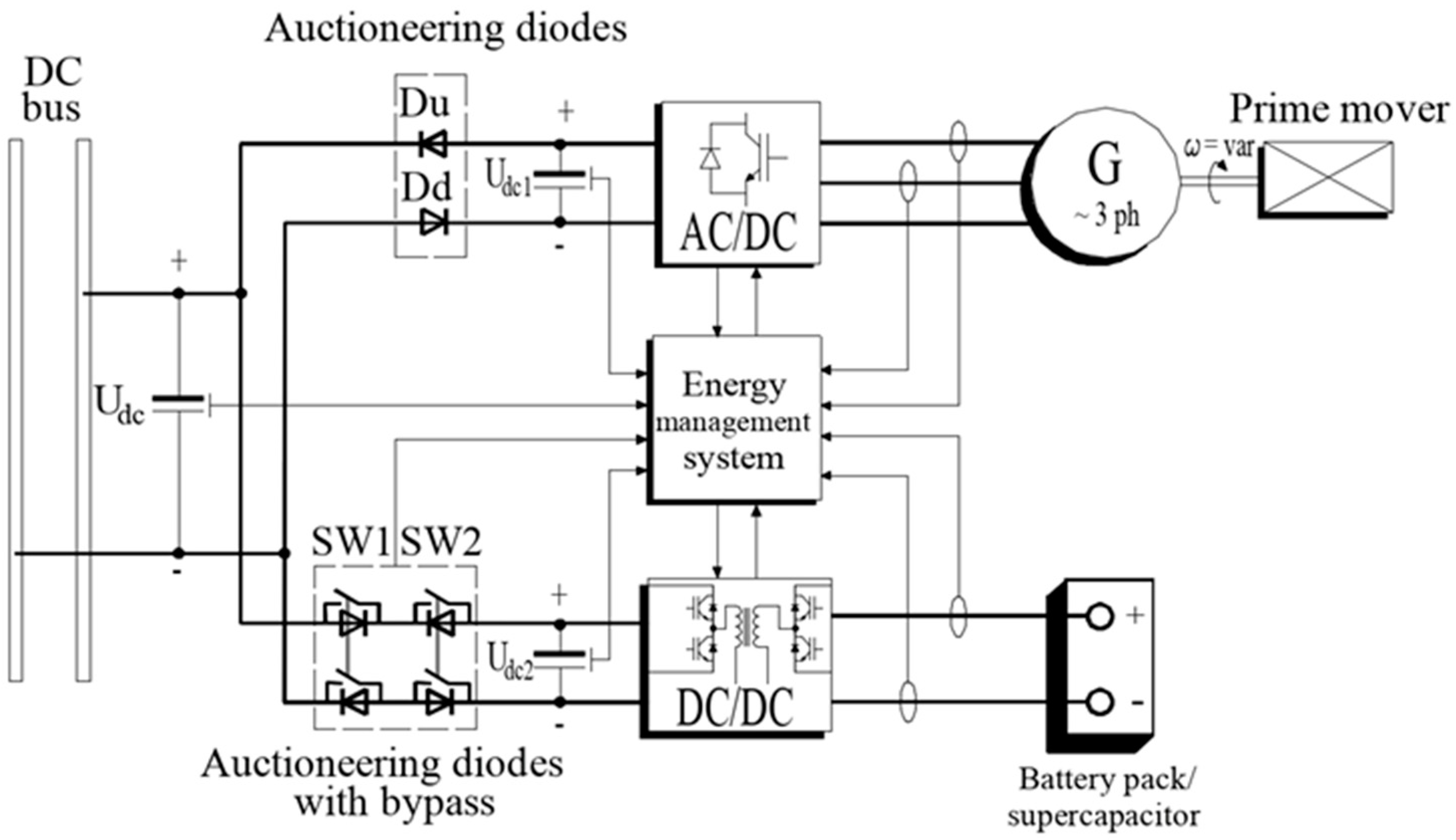
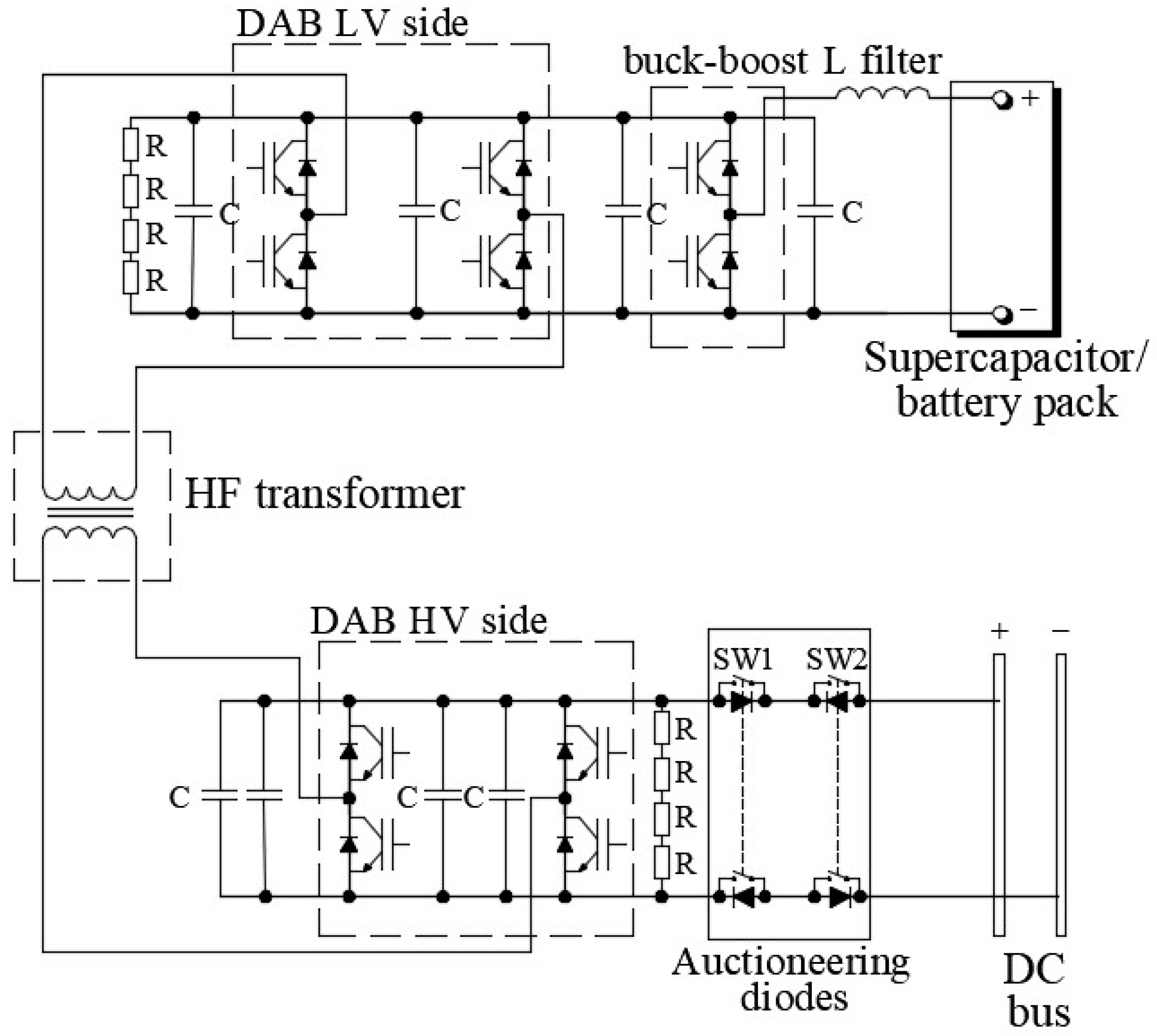
To connect the active and passive voltage sources, the topology shown in the
Figure 1 was utilized. The pack of batteries and supercapacitor as passive sources were used while the active source was a synchronous generator with line-side inverter. As it can be seen, the voltage sources (of negligible internal impedance) are separated because of the use of auctioneering diodes that restrict the flow of circulating currents. These currents, in turn, would prevent the correct power distribution and cause uncontrolled flow of currents with values dependent on source impedance. The principle of operation of the system consists in continuous changes of the values of the set voltages
Udc1 and
Udc2 so that the diodes of the AC/DC machine inverter and the DC/DC converter switch from the blocking state to the conduction state and enable the flow of the current, sustaining the set voltage of the DC network
Udc. As it is known, diodes are not perfect switches and, in this special mode of auctioneering operation, their properties become important. The most relevant, in this very application, is the reverse-recovery current flow during the transient time from conduction to the off state. The explanation of such is as follows. In the case of changing polarity, or when reverse voltage is applied to the diode, forward current flow stops and reverse current (recovery current) shows up for an instant. The recovery current value may oscillate depending on the conditions of use. Ringing is another term for this oscillation. The time it takes for a switching diode to turn totally off from an on state is referred to as the reverse recovery time, or
trr. Electrons cannot generally be halted immediately once an operation is turned off, resulting in some current flow in the opposite direction. The larger the loss, the higher the leakage current. Metal diffusion, material optimization, and the development of fast-recovery diodes that decrease ringing after recovery can all help to reduce reverse-recovery time but, for the proposed application, these are not applicable yet for technical reasons.
2.1. The Control Principles of the Proposed System
The presented system contains two main functional elements which can work separately or in parallel. These units are controlled independently and work asynchronously from each other. First, the control algorithm implemented in a dual active bridge controls DC voltage and keeps it on the fixed level. The DAB inner control loops can be preprogrammed to operate in one of the three modes:
- -
charging batteries,
- -
discharging energy storage,
- -
discharging with control and maintain of DC output.
In the third mode of operation, the system is precisely tuned just to maintain the resulting DC bus voltage and allow it to work along other DC voltage sources in parallel connection. In the proposed system, this DC-DC unit is considered the “master”; it keeps the voltage level in the power-distribution mode and draws energy from the batteries or supercapacitor. It can be easily programmed to work in the bus-voltage-following mode with active current limiting but this feature is not covered in the paper. This kind of operation in DC microgrids is known as master mode [
19] when the selected source keeps the voltage on a constant level and forces others to follow the voltage value within current limits. The energy management system should control such an operation and affect power distribution in the case of energy-storage voltage dropping below operational range. Another reason why DAB was chosen as superior system is that the converter works with batteries, which are sources of relatively slow voltage changes compared to the MSC, where the rotational speed can be quickly changed, thus resulting in back-EMF and generated voltage. This feature makes MSC control loops tuned to be prone to such disturbances and sometimes this kind of erratic behavior may arise in control instabilities especially in the systems with number of active sources [
20].
Because of the aforementioned reasons, the machine-side inverter was a more convenient choice. The main control loop could be modified easily to use as the following source in the load-power sharing mode.
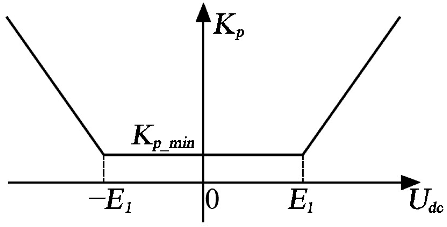
On the other hand, in the independent mode of operation of machine and its inverter’s main control loop keeps the DC voltage constant on the output and operates in a wide range of currents up to the nominal value. The main nonlinear controller operates with different proportional coefficients according to the varying error signal value. For these values calculated in reference to the actual DC bus voltage, a set of coefficients is taken from the look-up table and inserted online into the software controllers.
As it can be seen in the
Figure 2, the difference between commanded DC voltage and its actual value can change rapidly due to heavy consumption of the operation, thus leading to a significant direct-voltage drop. This causes the proportional component to raise quickly, which affects control accuracy and leads to overshoot. In the islanding mode, these values should be limited mainly not to exceed the permissible values which are given in [
21] and to maintain the required dynamics.
However, things become more complicated when it comes to parallel operation of the voltage sources of small impedance. In such cases, a problem arises of very precise DC voltage regulation needing to be maintained in order to obtain proper direct current-sharing between controlled voltage sources.
In parallel operation, even slight inaccuracy of DC voltage regulation causes large differences in power distribution and, in case of low control accuracy (or notable Udc error), can prevent current-sharing. Because of that, the machine-side inverter control method should become more precise when there is a need to distribute power between voltage sources in parallel operation.
2.2. Synchronous Generator and AC-DC Converter Output-Stage Control Principles
The control of self-excited generators involves the regulation of frequency and voltage by adjusting active and reactive power. In the generating sets arrangement, a combustion engine provides active power, while excitation-winding current ensures reactive power. A rotational speed governor and automatic voltage regulator provide data for the two independent control loops. Simple, straightforward scalar-control procedures like this omit some phenomena, such as the coupling effect between synchronous generator electrical axes [
22]. Among the many suitable methods for this purpose is field-orientation vector control. Since AC machines use vector control; their performance during transient operation modes is quite similar to that of direct current machines. Space-phasor theory provides the mathematical foundation for the dynamic model and vector control of AC machines [
23]. A rotor-flux-oriented synchronous machine model can be used to simulate DC generator operation, but a field-oriented model is used for controlling the generator. In a sense, this concept resembles a DC machine in which the two variables are controlled independently to produce electromechanical torque. The DC machine, equipped with commutator, produces top torque in comparison with almost any AC machine due to its mechanical alignment of the commutator and, thus, the perpendicular orientation of armature current and a stator flux. Nowadays, such a case is not considered because of certain problems arising from the brushes and commutator, and it can be stated that only brushless machines are in use in maritime industry today.
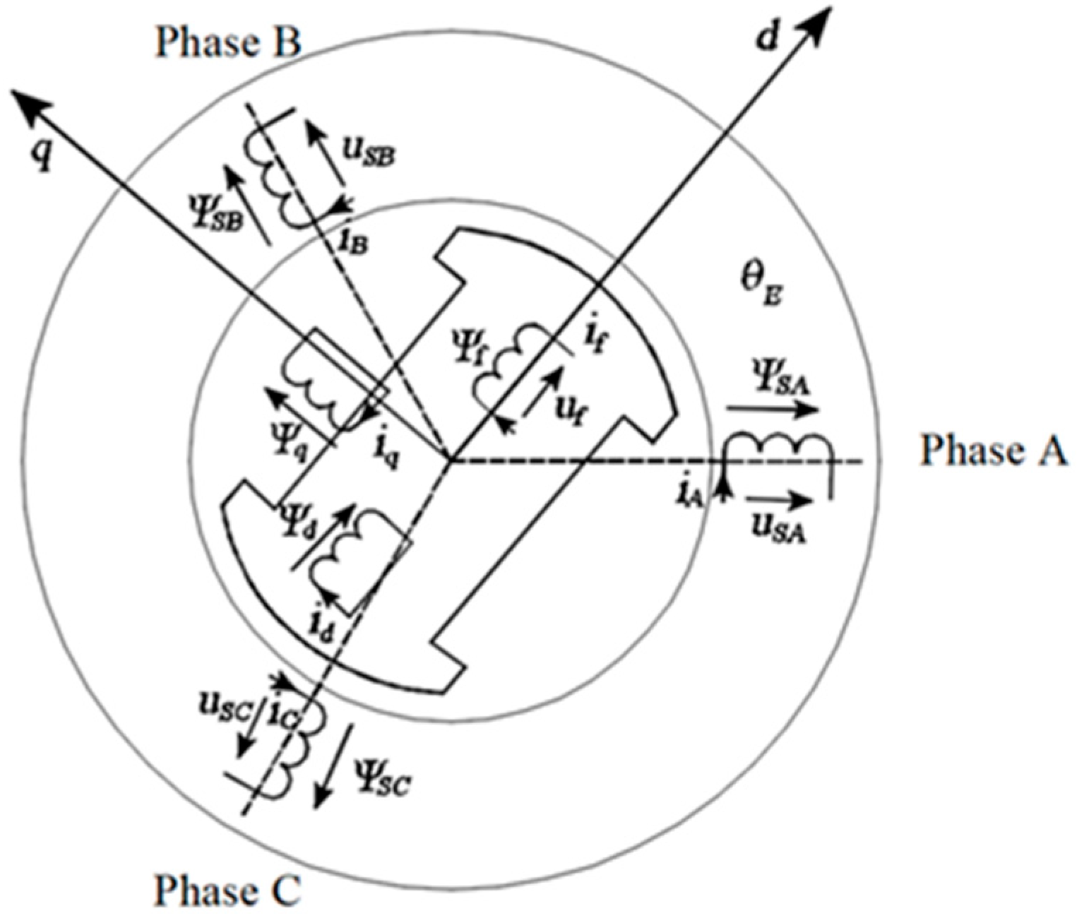
In the synchronous generator, the stator currents and magnetic fluxes depicted in
Figure 3 are given by:
where:
Ψsd, and
Ψsq are the stator fluxes in
d-q plane and
ωe is the stator magnetic flux rotational speed.
Quadrature in the generating mode determines active power and intermediate circuit voltage and, due to reversed energy flow, is negative. The flux component is also negative due to its demagnetizing properties and corresponds to the reactive power generated. An active current component creates torque by influencing the exciting current. Field oriented exciting currents have a longitudinal component due to decoupled control, which contributes to their magnetizing properties.
For power flow to be controlled, the stator current must be oriented in the direction of the magnetizing flux which is implemented in a control algorithm using Clarke and Park (
α-β and
d-q) plane transformations. A constant torque-angle control strategy maintains the current vector on the
q axis aligned with the current vector on the
d axis at all times. Considering both
isd and
isq currents in a synchronous generator, the torque equation is as follows:
where:
Ψm is field winding flux,
p is the number of pole pairs and
Lsd and
Lsq are values of the stator self-inductances. As a result of some simplifications, the torque equation becomes:
Because machine torque and active current are linearly related, Equation (4) shows that the generator can be controlled by means of stator current and flux mutual regulation. In the
d-q coordinates, the
isq independent control loop assures that the DC intermediate circuit voltage
Udc is always a non-zero value even when the reactive current
isd is equal to zero. As it can be seen in
Figure 3 to control PWM inverter the signals of
d-q plane voltages are applied. To achieve such there is a need to translate current signals into the voltages. From a theory, this conversion is done with following dependencies coming from (2):
where
vsd and
vsq are the d-axis and q-axis stator terminal voltages and
Rs describes the resistance of the stator phase windings.
In (6), substituting term
ωr Ψm, which describes back EMF, with
E and applying a Laplace transform, we get:
In the FOC control method applied in this case, the magnetizing current
isd is kept at 0 (by decoupling term) so the part including active current in (7) can be canceled, thus the transfer function of the machine is given by:
Introducing electrical time constant
τsq in (8) yields
In the presented solution, a sensorless system was utilized to obtain the angular speed and stator-field-angle values needed for Clarke and Park transformations. More detailed information is included in the
Appendix A. This control method utilizes a flux-angle calculation block that takes information from observer, which in fact is a block of the control digital signal processor software running real-time parallel with machine. The current values used in the flux calculation block are filtered out due to noise coming from current sensors, providing smooth operation of the control system. The speed calculation equations are fed with measured current values and known voltages applied to the windings. This allows for calculation of flux in reference
α-β plane which in turn leads to reference-frame angle calculation. This is needed to provide information for forward and inverse Park transformation crucial in FOC control and can be useful in rotational speed estimation.
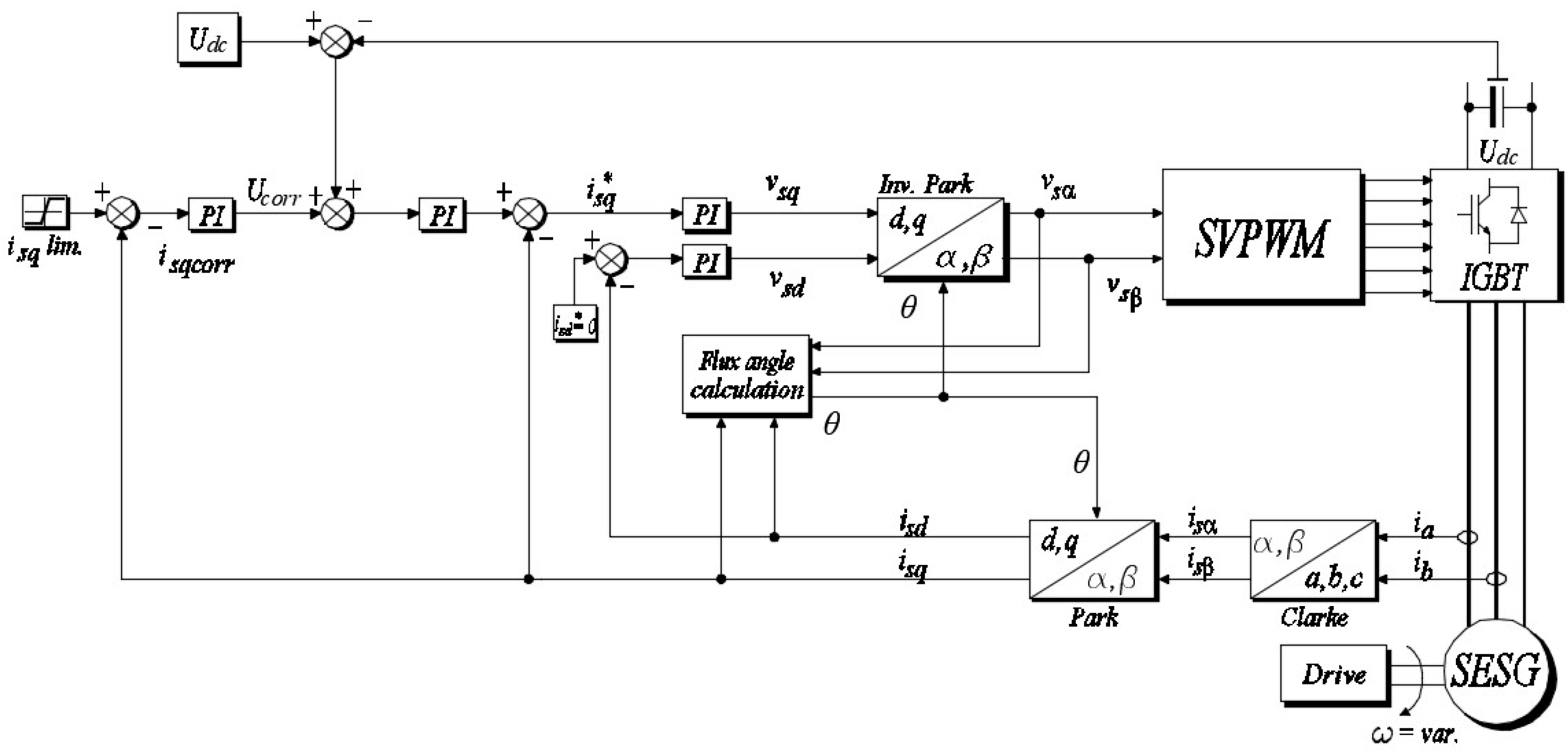
There are three main control loops in the proposed structure: the DC voltage outer loop and the active along with magnetizing current fast loops (in
Figure 4 denoted as
isq and
isd currents) which is consistent with the classical FOC scheme. Besides providing long-term voltage regulation for DC intermediate circuits, the field-oriented control technique also enables the distribution of power between parallel DC sources thanks to introducing active current limitations. What distinguishes the presented method from classical solutions is presence of the fourth PI control loop which produces a signal denoted as
Ucorr. In the islanding mode of operation, the DC link voltage is the main controlled quantity, so the regulator parameters are tuned for dynamics of such. Regarding the active-current limitation, correcting the voltage-signal provides power distribution instead of limiting
isq current in the main loop, which should be set to the nominal value of the machine and inverter value. The correction loop is enabled in the case of parallel operation and can be limited not to exceed safe operation area of the inverter’s DC intermediate circuit voltage. This additional control loop eliminates nonlinear regulators; moreover, it enables precise and fast voltage control when power-distribution mode is required. As it may be deduced, an additional corrector control loop should be used in parallel-operation mode, limiting active-current contribution to the consumer. Another important issue is parameter variations occurring during system operation. The proposed parallel-connected system inherently is not ideally stiff, which means that both sources cannot keep intermediate voltages on the required level in the operational range. In the case of simple DC voltage control, fluctuations of the intermediate voltage generated by the DAB contributing to incorrect power distribution. It follows from the methodology of a system without an additional regulator that, in order to be able to limit the current, the DC bus control voltage must be increased by adding a certain value to the reference level. This value should depend on the current state of the bus voltage so that the load current distribution can be precisely regulated. Because in the parallel operation the voltage measurements are common for DC bus and intermediate circuits connected these values cannot be precisely determined without active-current control.
In order to check the correctness of the assumptions, a simulation system was set up and its most relevant parameters are shown in
Table 1.
The numerical simulation was prepared in the Matlab R2022b (MathWorks, Natick, MA, USA) software using parameters of modelled SESG later used in the experimental test.
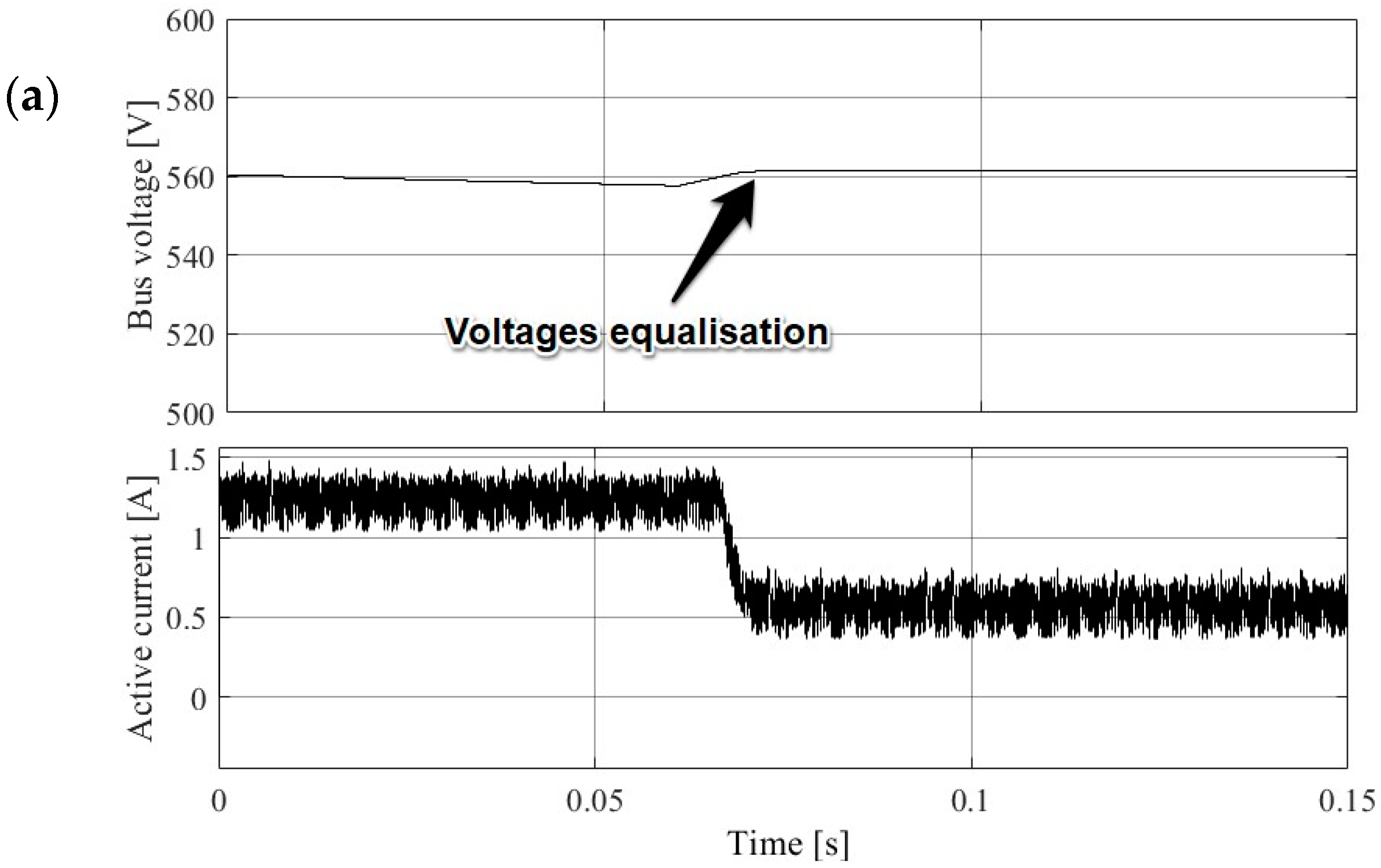
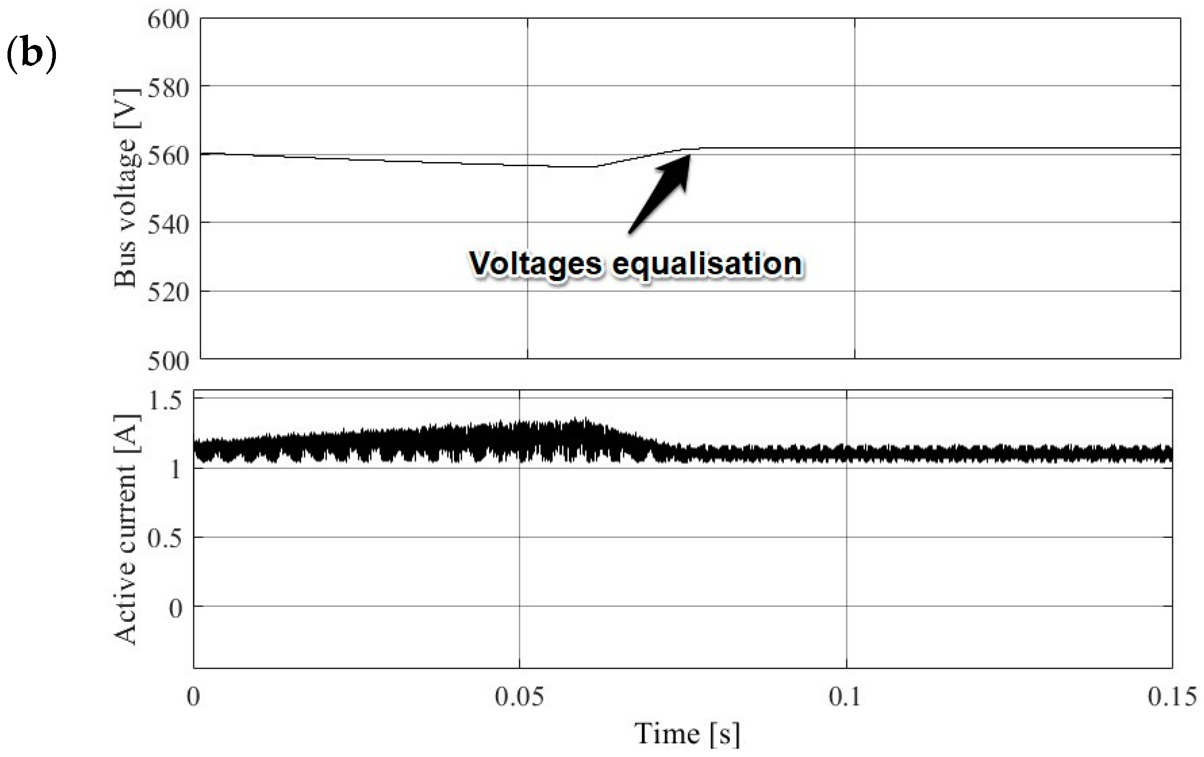
In
Figure 5, there are presented numerical simulation results depicting the situation of unequal voltage intermediate circuits in two cases. In the
Figure 5a, the control over DC voltage relies solely on the main loop PI control, while in the
Figure 5b, the compensating controller was used. In the time of bus voltages equalization, the system without active compensator does not take any action when the current drops below the limit, thus the load-power-sharing operation is not maintained. Such an unfavorable situation leads to conclusion that the reference voltage setpoint should be changed either on the master or the slave-controlled voltage source every time current sharing is needed. In such conditions, the only way to determine shared load ratio between paralleled sources is by active currents control, so the additional compensator loop is necessary. Over a limited range of parameters, the proposed method uses a PI controller configuration and a first-order plus dead-time model. Further, all approaches involve tuning cascade control systems in two steps: first, the secondary controller is tuned based on the dynamic model of the inner process; second, the primary controller is tuned based on the dynamic model of the outer process, including the secondary loop. Consequently, if the secondary controller is retuned for some reason, an unfavorable identification step can result in an additional retune process for the primary controller.
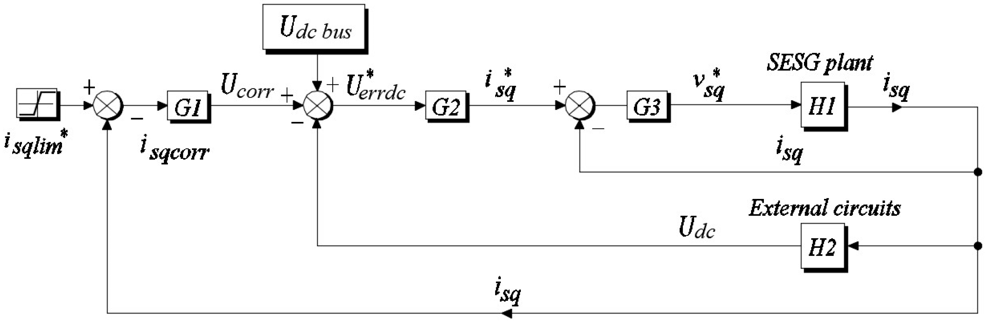
2.3. Synchronous Generator DC Voltage Cascaded Control
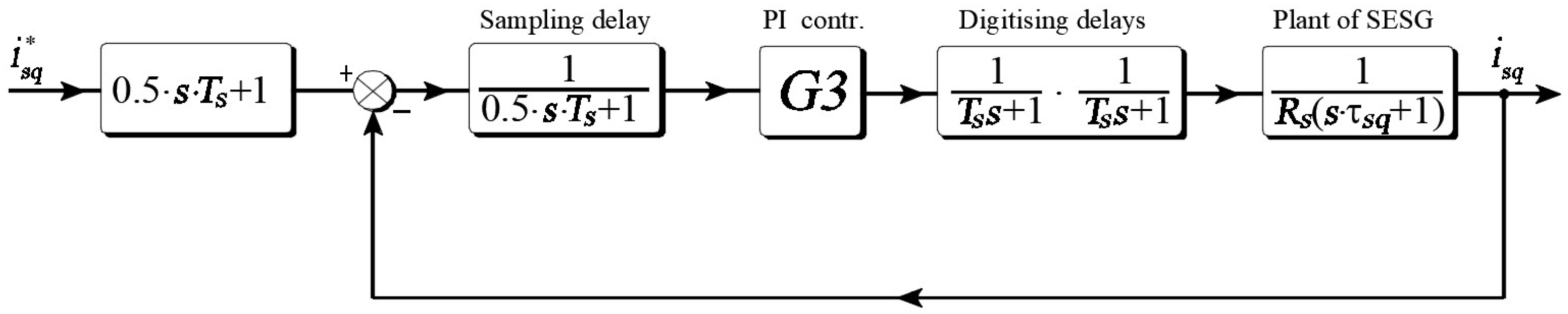
One method allowing for precise control proposed is a modified control closed-loop enhanced in comparison to a basic current-regulator form with additional corrector controller. According to
Figure 4, the cascaded control loop part can be presented as follows.
Where: Udc bus is the actual voltage value of DC bus, U*errdc is the voltage error differential signal, Ucorr voltage the correcting signal, isqlim denotes active current limit, isqcorr is the corrector current, G1, G2, G3 are PI controllers, H1 is the generator plant, and H2 is the external circuits block.
The control loop consists of SESG plant
H1 block, which can be presented as follows:
The block
H2 describes external circuits, which in the presented circuit include capacitances and resistances of common DC bus bar.
where
Rext and
Cext are the external circuit resistances and capacitances.
The PI controllers are responsible for control signals of DC voltage outer loop, internally calculated active current and the corrector current. The auxiliary measured variable is an active current isq, which feeds the DC bus consumers and is crucial to maintain the proper value of direct voltage. At the same time, the value of the isq is critical for the sharing-load control method. The current-limit value comes from an energy management system and fulfills the current-sharing requirements, which means the control of the outer loop is the main measured variable and relies solely on active-current limiting.
The scheme shown in
Figure 6 depicts dependencies between controlled variables, PI controllers, and the active-current limiter.
In the presented loop, the controlled and corrected variable is the active current
isq. This current charges intermediate circuit capacitors and, in parallel, powers up external circuits. According to
Figure 6, the equations describing inner control loop of active current and resulting DC voltage (all components are in the s-domain) can be expressed as:
The outer, voltage control loop can be presented as:
From
Figure 6, the voltage error signal is as follows:
After applying (15) into (14) we get:
In the proposed solution, the error voltage along with
G2 controller signal gives the information proportional to required active current. In the slave loop, commanded active current is compared to actual value and the result is transformed to machine-side inverter voltages. Such a structure is used widely in control applications regarding real-time machines control and works flawless in the single mode of operation. Presented configuration refers to the cascaded control and is functional enhancement of a single-loop control. The quality and performance of the cascaded control loop mainly depends on parameters [
25] and coefficients of master and auxiliary loops controllers. In theory, for such cascaded systems, the frequency response methods are used to set the controllers properly [
26]. Open-loop transfer function of the main loop has higher order dynamics than inner loop in the control algorithm. There are available tuning charts allowing the prediction of the master controller settings for minimizing integral of time-weighted absolute error due to load disturbances on the secondary loop in cascade control systems. Because of the use of controllers, one needed piece of information deals with stability of the system and can be obtained with means of classic analysis in s-domain. To achieve such, the transfer function of the control loops should be defined. After some simplifications on voltage, Equations (5) and (6) the transfer functions of current loops for SESG are as follows:
where
s is the complex variable.
Having the parameters of the real-time system, such as computational delays and circuit time constants, it is possible to put together a control-system loop without corrector.
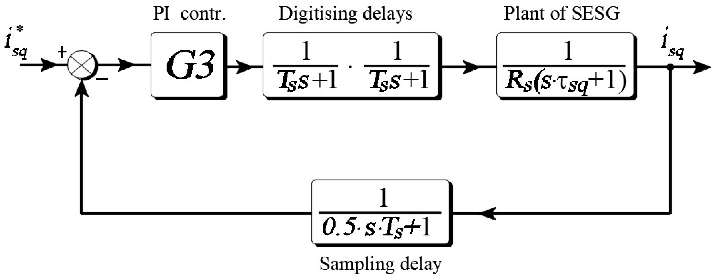
The detailed active-current control loop in its generic form is shown in the
Figure 7. The active current set point is compared with its measured value and the error signal feeds PI controller. The PI controller in continuous-domain transfer function, according to [
27], can be expressed as:
where
is a PI controller gain.
To obtain required transfer function, the input function 0.5·
Ts·
s + 1 should be approximated and presented in more convenient form, which is
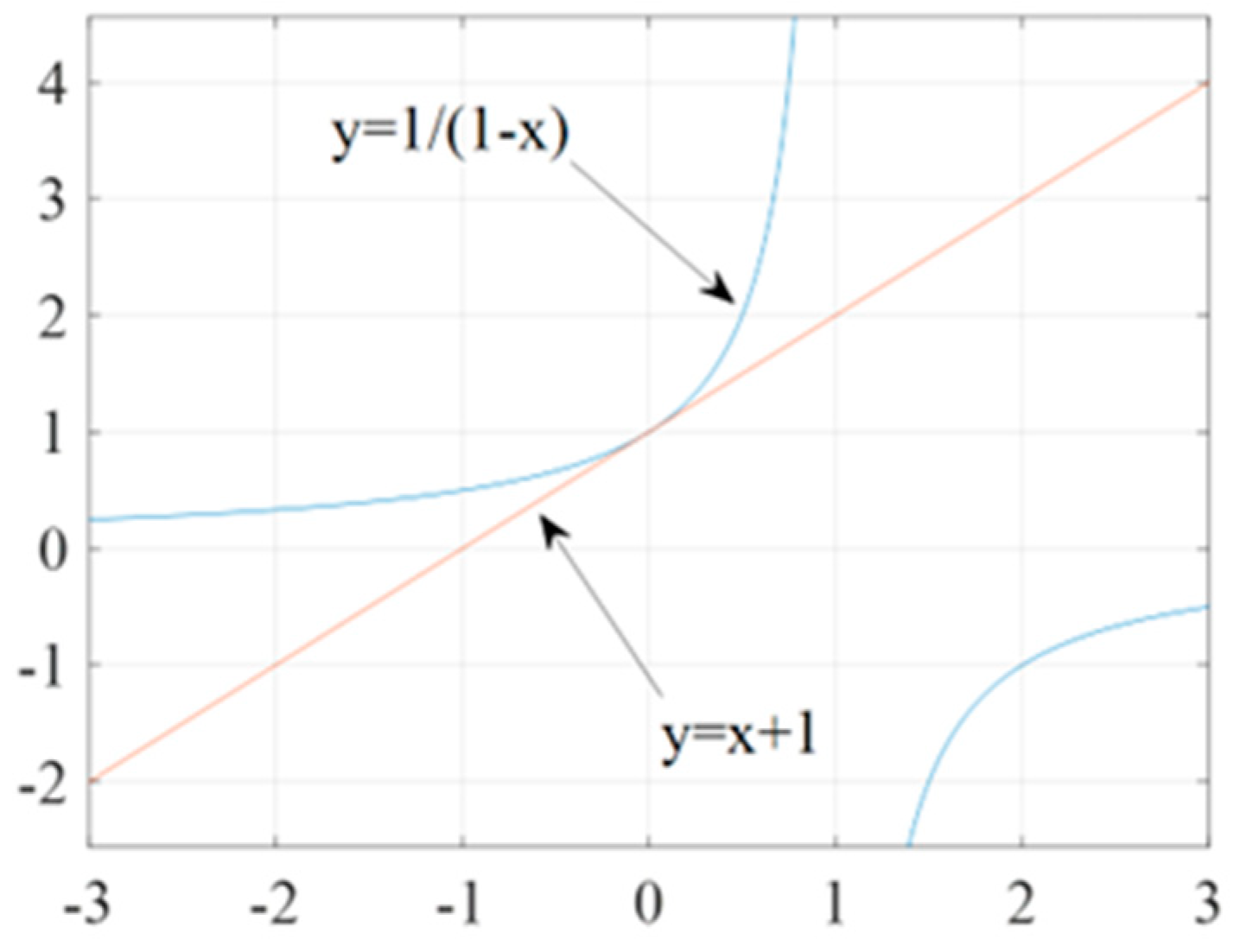
. The way to achieve this is to linearize this function around a fixed point described as (x
0, y
0) = P(0, f(0)) = P(0,1). Graphical representation of the function linearization around given point is shown in the
Figure 8.
The equation of the tangent in the general case has the form , while . In the given situation and finally we have an approximation of .
In order to obtain required loop feedback, the control configuration was rearranged with use of the introduced approximation which made it possible to obtain unitary feedback. Having the open-loop transfer function derived, the root-locus plot was prepared. Based on the plot, the slowest pole can be identified so the zero of the PI controller must be set in order to cancel out slow pole and, based on this, the time constant can be calculated.
In the next step to get the PI controller gain equivalent open-loop transfer function (including delays and time constant) is derived that looks like one below:
Because the discussed plant is a low-order one, it is convenient to use modulus optimum criterion (MO) for controller tuning due to its simplicity and good, fast response.
When there is one dominant time constant in the controlled system and one dominant time constant in the standard form of the control system, transfer function for the modulus optimum is achieved by cancelling this largest time constant [
28]. According to [
29], the optimal step response is obtained when the damping factor which is
. With such assumption, and using MO criterion, second-order transfer function can be expressed as:
By comparison (21) with the equivalent open loop TF, the PI gain can be found. Based on machine parameters and control system properties, the open-loop transfer function was created and, after applying modulus optimum criterion [
30], the proportional gain of the active-current controller was determined.
After inserting the transfer functions of plant H1 and H2 along with G2 and G3 controllers given by (18) into (14) and including required calculation along with the digitizing delays, the stability of the cascaded control loop has been proven.
It should be pointed out that the tuning process is crucial in order to obtain the needed step response from the designed system, and values which work flawless in digital simulation probably would need some more work in a digitally controlled laboratory setup.
The control signal goes to the real-time DSP-FPGA control system, which introduces digitizing and calculation delays; SESG itself also has a delay, which mainly depends on the electric constant of the investigated machine depicted in
Figure 9 as
τsq. This value was calculated based on the data acquired in the previous projects regarding an investigated machine.
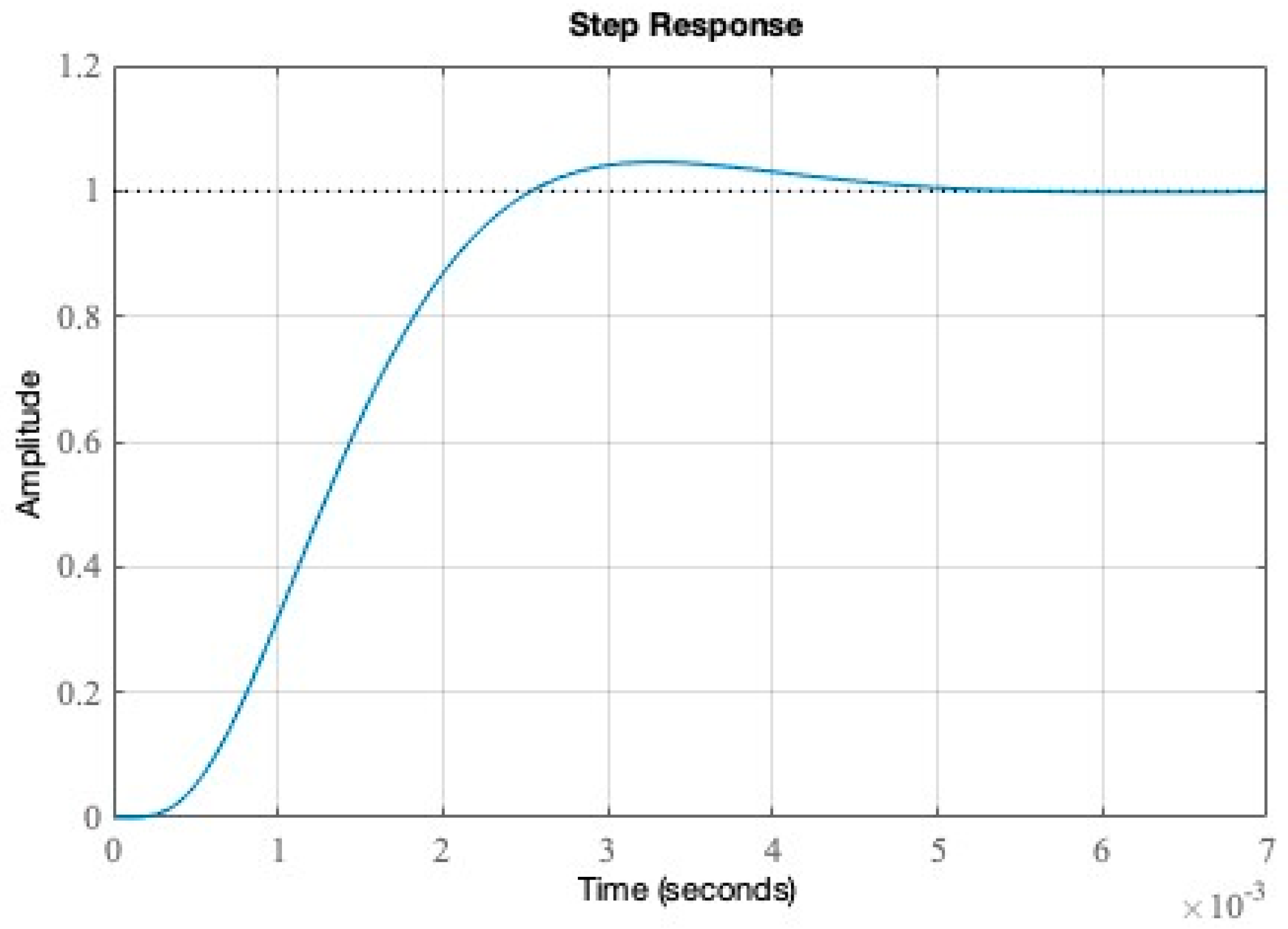
All data were included into control loop that allowed us to plot a Bode diagram of the investigated open-loop system. The transfer functions have been implemented to Matlab R2022b software and, for the chosen set of parameters, the obtained step response is as in the
Figure 10.
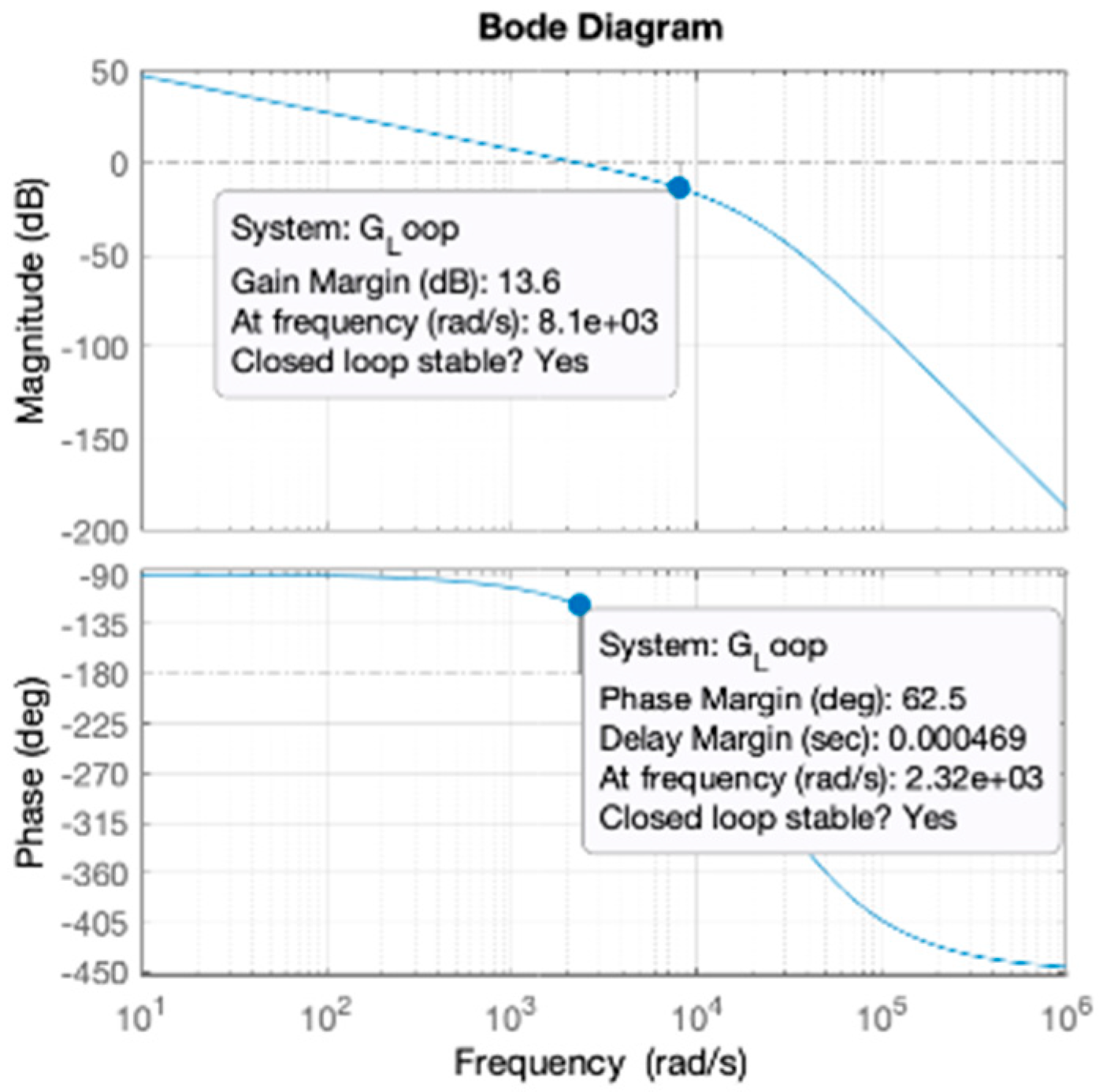
For the given data of machine parameters, it can be read from the Bode diagram in
Figure 11 that the phase margin is equal to 62.5 deg while the gain margin is 13.6 dB and both are stable for closed control loop.
Similar calculations and tests were performed to obtain information regarding stability in the isd current loop and Udc based on (16) so the stability of the control was proved.
2.4. Synchronous Generator and DC-DC Converter Output Stage Control Principles
In addition to the synchronous generator inverter, the complete system includes a bidirectional converter tied to the batteries pack or supercapacitors.
In the
Figure 12 there is a complete system of DC-DC dual active bridge converter presented.
The control of the converter is based on a variable phase-shift angle, which, by changing the phase-shift angle of the control signals of the two bridges, allows the possibility of stabilizing the output voltage, and, at a certain load, regulating the active power in a control system. Physically, DAB control is achieved by generating two PWM signals at half-duty cycles that are phase shifted from each other. The greater the phase difference is, the greater the power flow through the converter [
31]. As it can be noted, a DAB contains low-voltage (LV) and high-voltage (HV) sides, which are galvanically separated with a high-frequency (HF) transformer. This ensures lack of dependency between closing transistors on both sides of converter. The dual active bridge utilizes two modes of operation. In the first mode, a converter charges batteries and a combination of switches, denoted as SW1 and SW2, along with parallel-connected auctioneering diodes, allows current-flow solely into the batteries from the power DC bus. It allows for a direct-voltage input ranging from 300 V up to 700 V and, with the use of one phase inverter, changes current into 21 kHz quasi-sinusoidal waveform.
High-frequency switching is needed to avoid the typical noise and then is transformed with use of high-frequency transformer of 1.87 voltage ratio. This unusual ratio value ensures almost trapezoidal/square voltage waveform, which in turn creates a minimal amount of higher-order harmonics and makes the system more efficient. The core of power flow control is achieved by input/output square voltage phase-shift control and with use of the presented dual active bridge it can work with minimal set of voltage and current measurements.
2.5. Diode Recovery Current and Ringing Effect
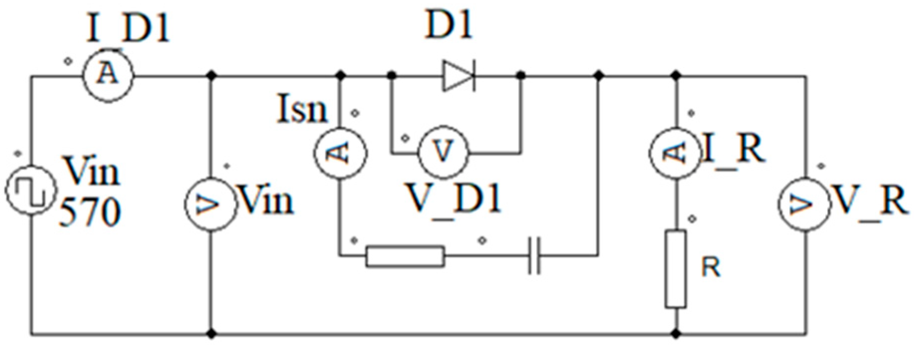
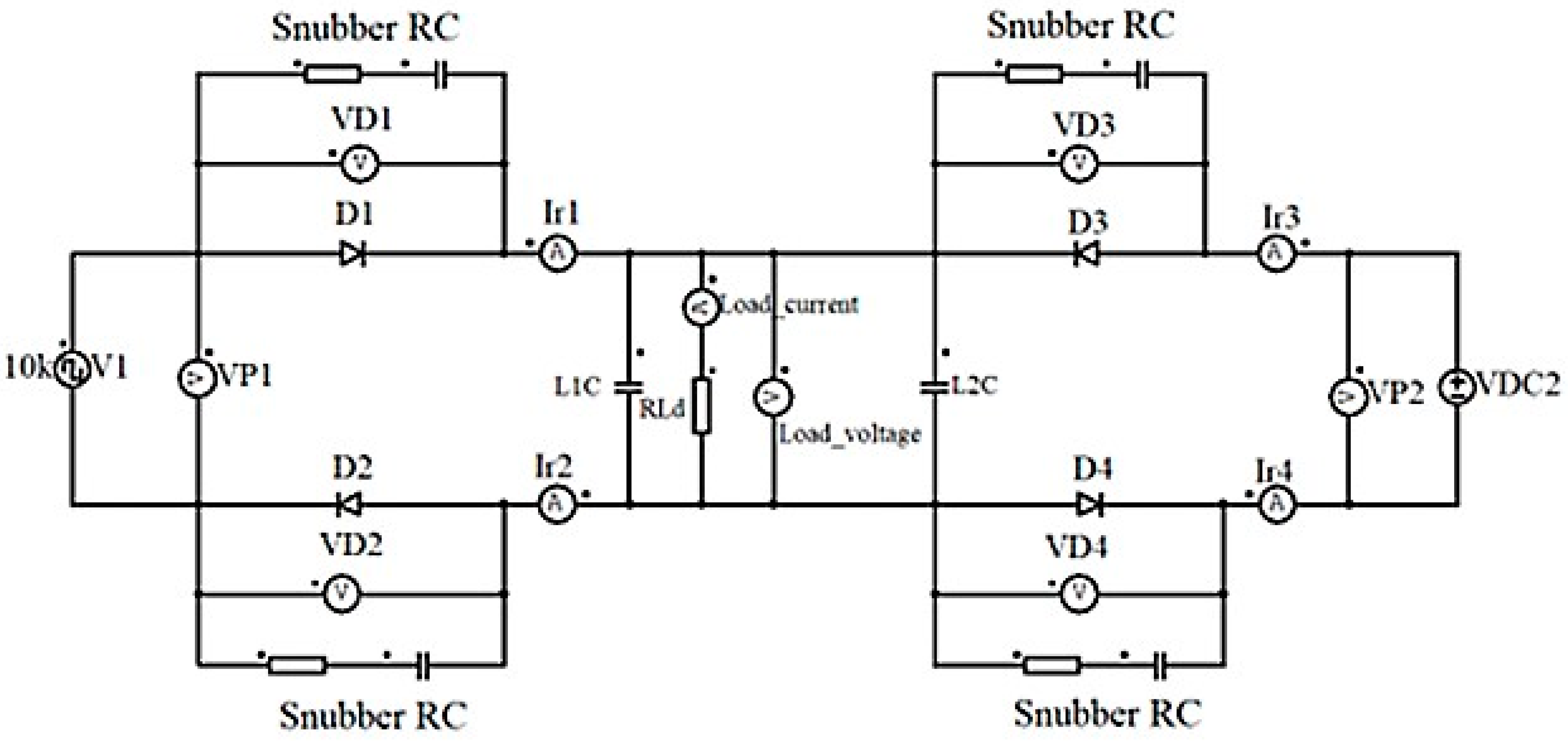
To verify the validity of the assumptions regarding the use of auctioneering diodes in the power distribution system, appropriate circuits were created in simulation software.
The prepared layout was put together from elements that had the detailed parameters of real semiconductor devices. The entire simulation rig is shown in
Figure 13.
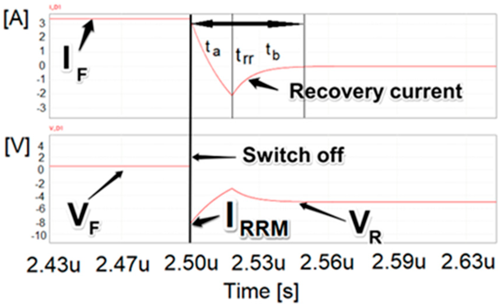
First, to recall how the diode conducts and gets into off state, it is important to realize that these processes are not instant, and the diodes are not ideal switches. There are few important parameters such as recovery time, which occurs during transition to off state.
After forward current flow, reverse current flows for a moment when reverse voltage is applied to the diode. The result of this reverse current flow is referred to as recovery current. When conducting forward current, all junction diodes store charge in the form of excess carriers. Minority carrier injection is a conductivity modulation mechanism causing the forward voltage to drop, which is favorable in this case.
The stored charge must be removed or neutralized in the PN junction before the diode gets to the off state during the diode commutation process. Reverse-recovery time is the amount of time it takes for this to happen
trr and is made up of two different intervals denoted in the
Figure 14 as
ta and
tb.
A diode that conducts forward current has a corresponding forward voltage drop VF and a stored electrical charge proportional to the forward current. Recombination process neutralizes a portion of the internal stored charge when the diode current commutates. Recombination process and reverse current Irr flowing across the diode and associated circuit parts diminish the remaining stored charge.
The forward current IF eradicates at a rate di/dt defined by the circuit inductance and the applied voltage while commutation process in the diode. When the diode current drops to zero, stored electrical charges force flow of the reverse current until the diode junction area is totally depleted.
The voltage drop across the diode is still positive throughout this section of trr, but it is smaller than the value of VF during forward conduction. In typical diodes, the current flowing during ta can be substantial. As a result of the low voltage drop across the diode, the diode’s power dissipation during ta can be considered as minor. The semiconductor element, on the other hand, may have a large power dissipation because it carries the full-diode reverse current while supporting the circuit’s full voltage. A diode with a smaller reverse current allows work at a lower temperature.
The voltage across the diode rises from a small positive value to the entire reverse voltage applied during this time. During tb, there is significant power dissipation in the diode due to the simultaneous reverse-current flow and high voltage drop across it. To reduce power loss during this time, one may infer that the diode with the shortest tb should be used. The area under the current-time curve during trr is defined as the total reverse-recovered charge left denoted often as Qrr. The energy that must be expended in the power switching side of the circuit is represented by this charge.
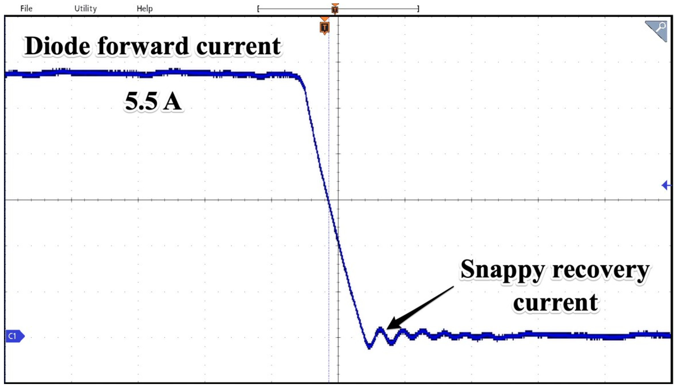
Another common problem in diode switching process is so-called ringing of recovery reverse current shown in the
Figure 15. This process can be observed under unfavorable combinations of commutating-current rapid increases, circuit stray inductance, forward-current small value, and, in the case of low p–n junction, temperature. As a result of snappy recovery, all fast-switching power diodes produce excessive voltage spikes [
32]. The operation of the presented system and its components is burdened with disadvantages as heat losses. Some calculations may be used to predict conduction and off-state losses in the junction which have a significant impact on diode power dissipation and junction temperature levels.
The diode’s total power losses can be computed as sum of conducting, off-state and switching losses.
The conducting state losses can be expressed as:
As the off-state losses are given by:
Finally, the switching losses are as follows:
where
Serr is switching energy losses due to reverse recovery and
f refers to the switching frequency.
Due to the complexity of diode dynamic recovery characteristics determining switching losses is quite difficult. In most of the applications the total charge associated with diode recovery represents energy that will be dissipated among various components of the circuit and can be expressed as:
Due to the principle of operation of the presented system the determination of losses using (24) is very complicated mainly because of the nonlinear voltage-current characteristics of power electronic switches (diodes) and it will not be the subject of this paper.
As will be shown in the following sections, the operation of the proposed system depends mainly on the switching phenomena of auctioneering diodes. According to (24) the energy losses and heating of diodes will depend greatly on the switching frequency, which is directly depends on the working frequency of the control system. These losses are hard to predict due to independent control of parallel-connected subsystems.
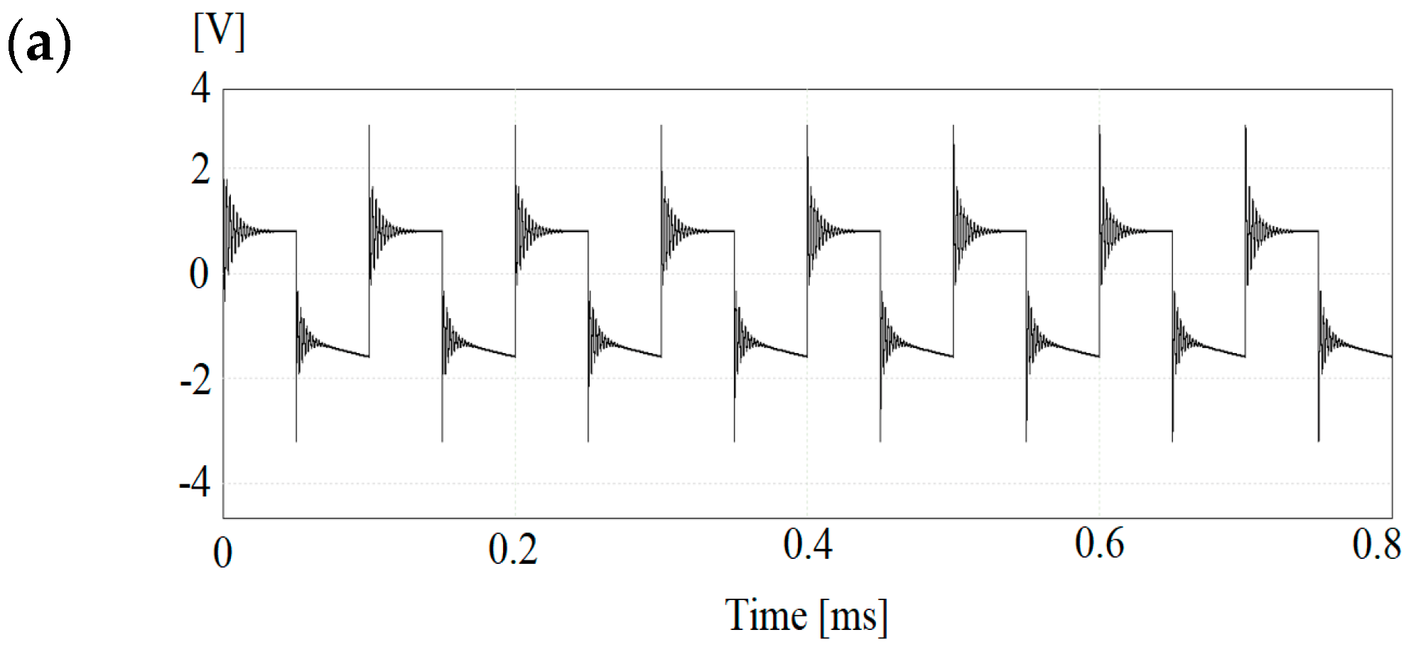
2.6. Simulation Results of Proposed DC Multipoint Distribution System
To verify assumptions regarding use of auctioneering diodes, the numerical simulation system was prepared and deployed under different conditions. To minimize oscillations (ringing) caused by switching-off diodes, the RC snubbers were introduced. Most of unwelcome voltage spikes and ringing can be observed on voltage waveforms across auctioneering diodes. One of the methods partially eliminating these situations is snubbers use connected in parallel with diodes.
These RC series connected snubbers provide a significant amount of protection for power electronics components (transistors, diodes etc.) as well as reducing EMI, particularly in switching applications.
In power electronics, resistor-capacitor (RC) networks are commonly used to reduce voltage spikes caused by parasitic capacitances and inductances in transformer, inductors, diodes, transistors, and systems, allowing transistors and diodes to handle more power.
Because of a mutually resonant relationship between inductances and capacitances, those spikes can cause EMI/EMC problems with both conducted and radiated emissions.
In situations where RC snubbers cannot be used, resistors or ferrites are used to introduce losses, especially when the ringing frequency is not significantly different from the switching frequency.
As illustrated in
Figure 16, the snubber RC is made up of two components combined in parallel with diodes. Such a solution is often used in switching applications like inverters and DC/DC converters.
Usually, the proper values of the RC ladder must be determined with experimental procedures and/or by trial and error with a real prototype. The ringing problem is related to parasitic parameters (e.g., inductance), so simulation results alone cannot be used to optimize the proper values of filtering elements. The procedure leading to the determination of the snubber resistance value can look like the following. First it is necessary to know the value of the ringing frequency to calculate snubber resistance in a way that it adds some losses needed for oscillations disperse. The ringing in such circuits is related to underdamped resonance, which comes from very low energy losses so the capacitance alone is not enough for snubber applications. The needed frequency can be taken from oscilloscope waveform and analyzed. Then it is convenient to measure self-inductance of circuitry and calculate the capacitance of the snubber. Another method that helps with the determination of snubber parameters is parallel-connecting capacitors
Cp of different values to reduce ringing frequency to half of the original value. Then it is possible to calculate snubber capacitance
Csn as a third part of the chosen capacitance according to following:
From the equation of resonant frequency, the inductance of circuitry can be calculated as:
And knowing of that, the characteristic impedance of circuitry can be expressed as:
The snubber resistance in this case should be equal to the calculated impedance. To avoid direct-current flow across shunt snubber resistor there should be a series capacitor added in, which filters out higher frequencies but at the same time introduces losses. From such the bigger capacitance the higher losses so the value of it should be chosen carefully. The values needed for snubber calculations were taken by measurements of the application elements later utilized in experimental tests. Based on obtained values, the numerical setup was prepared in which the snubberless system consisting of the exact same auctioneering diodes was implemented and simulation tests performed. For comparison, the same circuit was created but with RC snubber and launched. The simulation software used nonlinear, exact diode models in which transient states and recovery current were implemented. The recovery currents described in the previous chapter were lasting from nanoseconds to even microseconds [
33] and in anti-parallel connection occurred a negative-current flow.
Simulation tests containing diodes with different recovery times, different sampling frequencies of sources, as well as RC snubbers and L-smoothing filters were performed and chosen results were presented in
Figure 17.
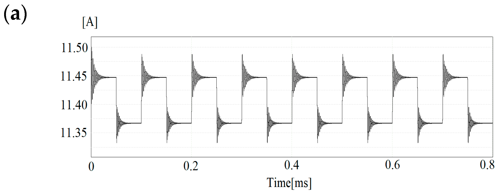
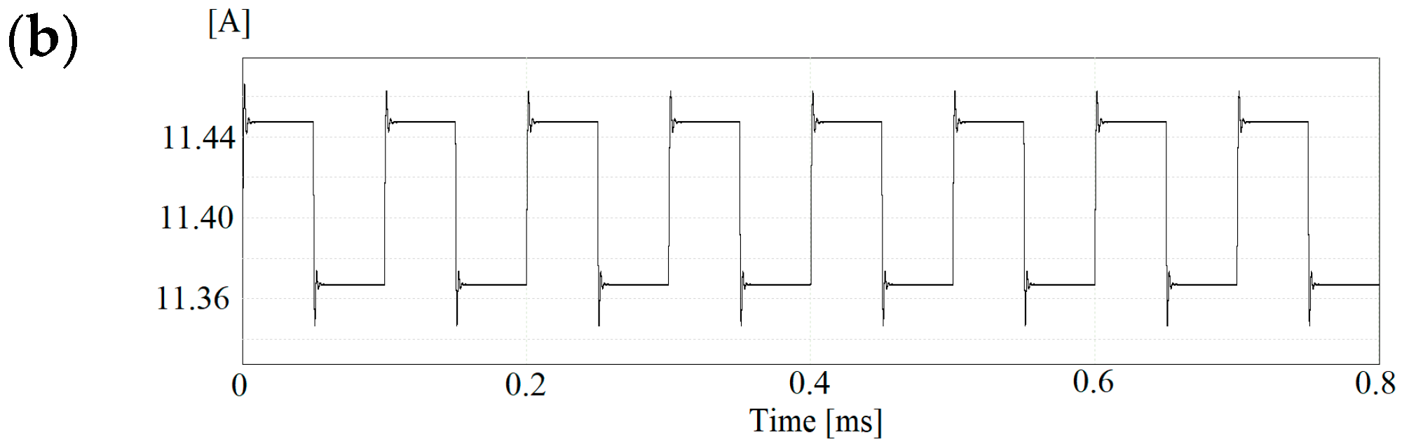
In
Figure 18a, there is current waveform acquired in the snubberless circuit while, in
Figure 18b, we present a case with snubbers present. The operation of the voltage sources in the proposed system with auctioneering diodes was also checked. In addition to providing information on the values of charging and discharging currents of the supercapacitor, the simulation tests revealed limitations of the system. Due to the nonlinear nature of the fast-charging process of supercapacitors, the simulation results were used to select the capacitor-current controllers in such a way that the permissible currents values generated by the machine inverter while maintaining stability of operation are not exceeded.
As a result of the analysis of results, there are important factors to consider when it comes to power distribution in DC grids. Among them is the use of RC snubbers in conjunction with diodes. While switching between diodes, a high ratio of current-raising di/dt can cause a lot of stress on semiconductors, so a proper filtering system is essential to avoid this issue. Due to high switching frequency, the inner structures of auctioneering diodes are also unavoidably heated, thus high-power-control algorithms must consider this phenomenon and change switching frequency by means of changing gains in PI controllers. It can be concluded that there is a complete control over the power-distribution process in the DC grid.
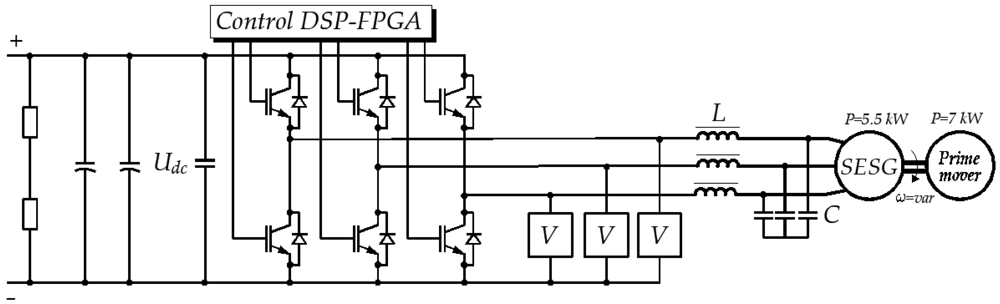
3. The Experimental Set-Up and Results
The laboratory test rig consists of an internally transformer-isolated 7 kVA DC-DC converter and a 7 kVA AC/DC converter that draws power from a synchronous generator. The 7 kVA synchronous self-excited machine is driven by a MMG50SR120B IGBT module. Using parallel-connected intermediate circuit capacitors, the total capacitance is equal to 200 μF and can withstand a maximum voltage of 1200 V. The switching frequency was set at 20 kHz due to the relatively small power of the loads. The DC-DC converter is based on CAS120M12 SiC-transistor half bridges. The boost-back converter operates at 21 kHz, while the bridges operate at 25 kHz. The supercapacitor used was BMOD0165 P048 with a nominal capacitance of 165 farads at 48 volts.
In
Figure 19 there is machine-side inverter system presented. For the voltage measurements, LEM CV 3-1000 transducers (LEM International, Meyrin, Switzerland) were used depicted as rectangles denoted with the letter V. When mounted on heat sinks, all auctioneering diodes were 16FR120M, capable of withstanding 1200 volts with 16 amps of continuous current. Direct-current two-pole contactors controlled by a PLC were used to connect the electrical consumers. DC-DC converters and machine inverters were equipped with their own DSP-FPGA controllers. The control units consisted of a processor board with an ADSP21363 (Analog Devices, Inc., Wilmington, MA, USA) digital signal processor, which was controlled by software. DSPs were used for processor-subroutine control programs, while FPGA board calls were made via processor subroutines. Analog-to-digital converters were incorporated into FPGA boards, and input signals were directed to DSPs through isolated transducers. Through dedicated hardware drivers, the FPGA controlled the IGBT transistors gating. The energy-management control board was based on the SH363-type processor and controlled both the machine and the energy-storage converters’ control boards. There are input/output ports on the FPGA board that are electrically compatible with an industrial Modbus RS485 two-wire port. Modbus communication lines have been equipped with optoisolation gates to reduce electromagnetic interference, resulting in a significant improvement in the quality of the transmitted data frames.
For the data acquisition, the 4-channel digital MDO3 200 MHz oscilloscope in the Hi-Res mode was used. The oscilloscope waveforms were taken at a time base of 2 s/div unless otherwise noted. It was demonstrated that the load-power-sharing feature of the presented system can be used in both battery and supercapacitor discharge and charging modes. Supercapacitors were initially charged to 43 volts, leaving safety limits for possible overvoltage spikes. After the line-side inverter was turned on, power was delivered to the DC grid through auctioneering diodes and closed switch S2 thanks to the phase-shift introduced by the storage-system inverter.
High-frequency transformer circuitry operated in discharging mode was equipped with auctioning diodes and current bidirectional switches (denoted as SW in
Figure 12) to prevent reverse-current flow from the DC bus to the primary winding. The DC voltage value at the output of the grid-side converter was set to 570 V and maintained by the control loop of the DC-DC converter. In addition, there was a direct-current limit applied to the control loop so as not to exceed its nominal value. The inverter’s intermediate-circuit voltage has been changed and a proper current limit has been applied to an energy-management system for controlling the DC bus synchronous generator’s power output.
The selected pieces of hardware of the proposed system are shown in the
Figure 20.
The chosen parameters of the laboratory stand and control system’s real-time software are summarized in the
Table 2.
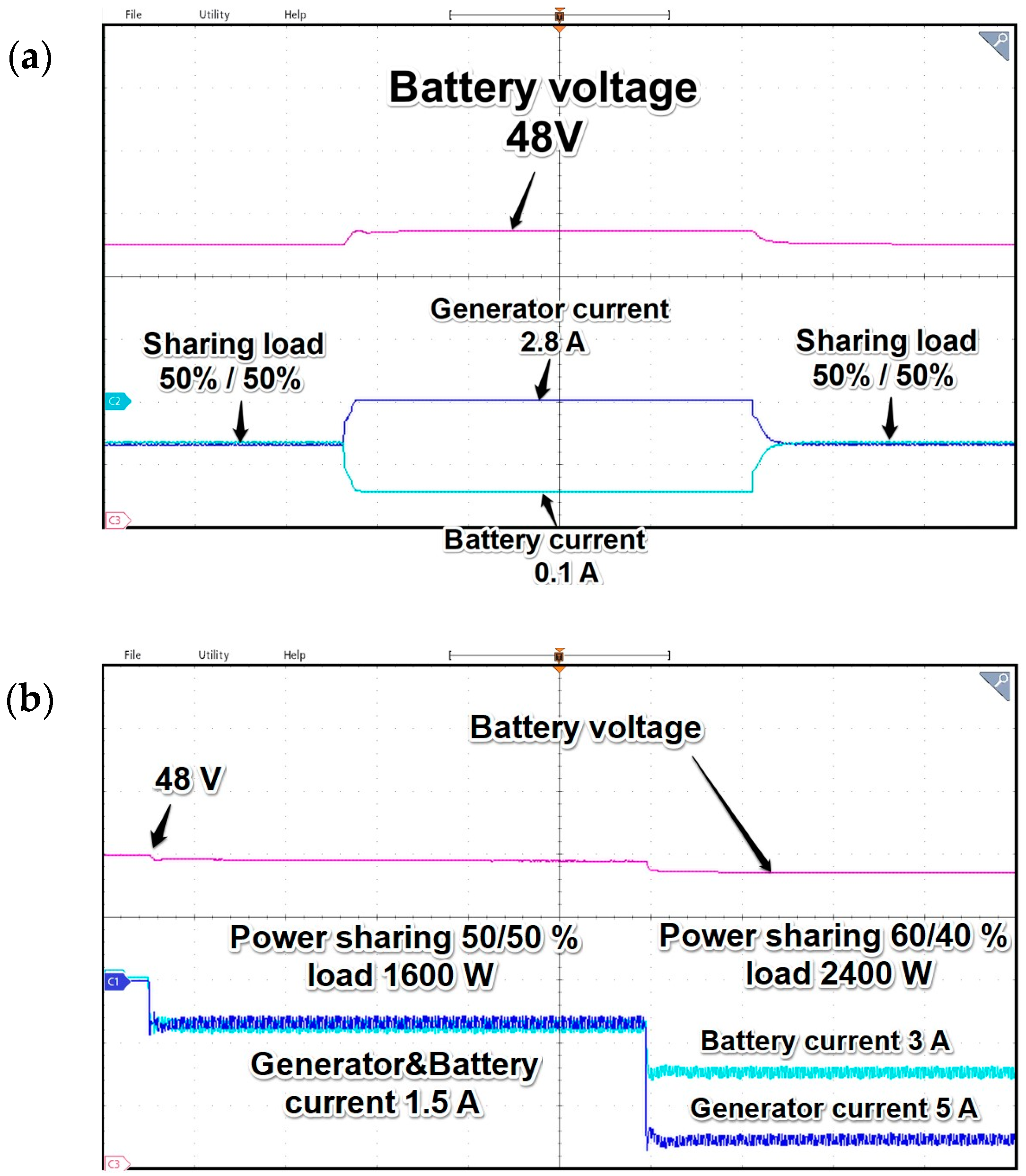
The voltage generated by the DC-DC converter voltage was applied to the DC busbar, and then the known electrical resistive load was switched on. The power electronics control system was able to control current sharing by changing the DC bus voltage precisely. Load-power-sharing operation and voltage quality can be improved by altering the DC-DC converter output voltage at the same time, but for simplicity, only the machine inverter-side voltage was used.
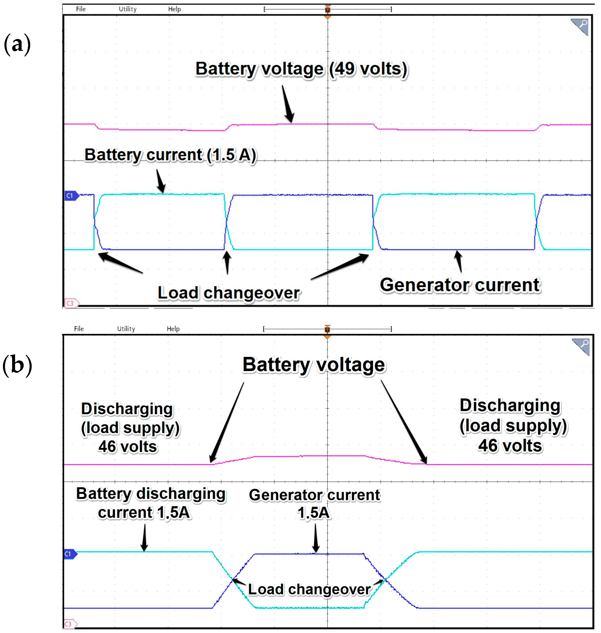
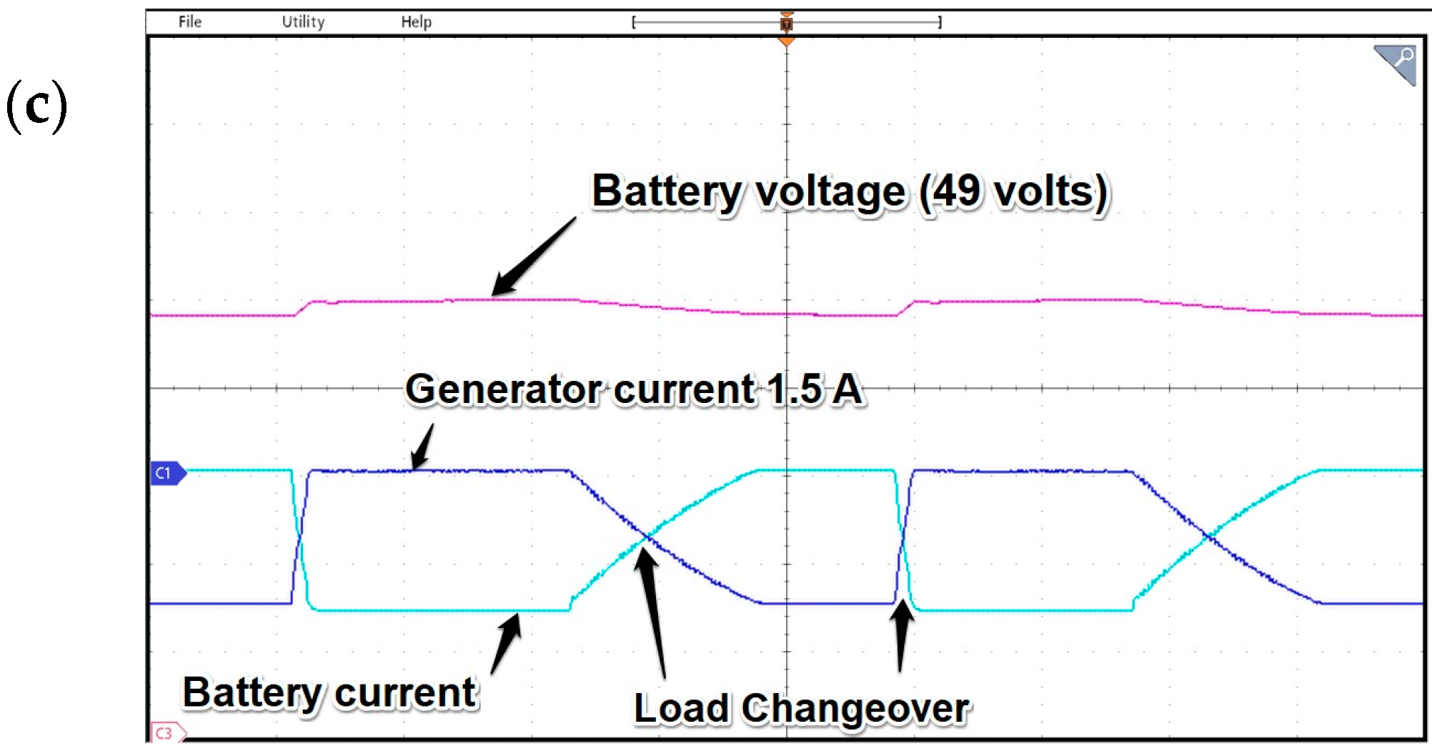
Just for comparative purposes, in
Figure 21 there are three drawings acquired for the system, with a cascaded PI regulator and a current waveform depicting operation of the earlier version of the system without cascaded controller.
It is clearly seen in
Figure 21c that, for given parameters reaching a power-distribution steady state, settling time after load changeover is much longer due to the system’s main controller settings. It can be noticed that, in the version without additional PI controller, there is no possibility of changing the dynamics of the sharing process and it is mainly based on the instantaneous values of the voltages at the terminals of the generator converter and the DAB.
As can be seen from the oscillograms in
Figure 22 and
Figure 23, when the system operates in power distribution mode, the waveforms of the obtained currents are controlled continuously, but due to hysteresis loops and phenomena in the auctioneering diodes associated with current-recovery ringing, their shape is not as precariously maintained, as in no power-distribution mode is enabled. As it was stated, the control of
Udc during power-distribution operation was possible due to the additional control loop of accurate active-current limit. As it turned out during experimental research, changing the active current
isq of the generator and inverter by 10% required a change in voltage
Udc of about 0.3 V. It must be noted that such subtle changes cannot be achieved with means of linear gains in the single controller PI voltage loop.
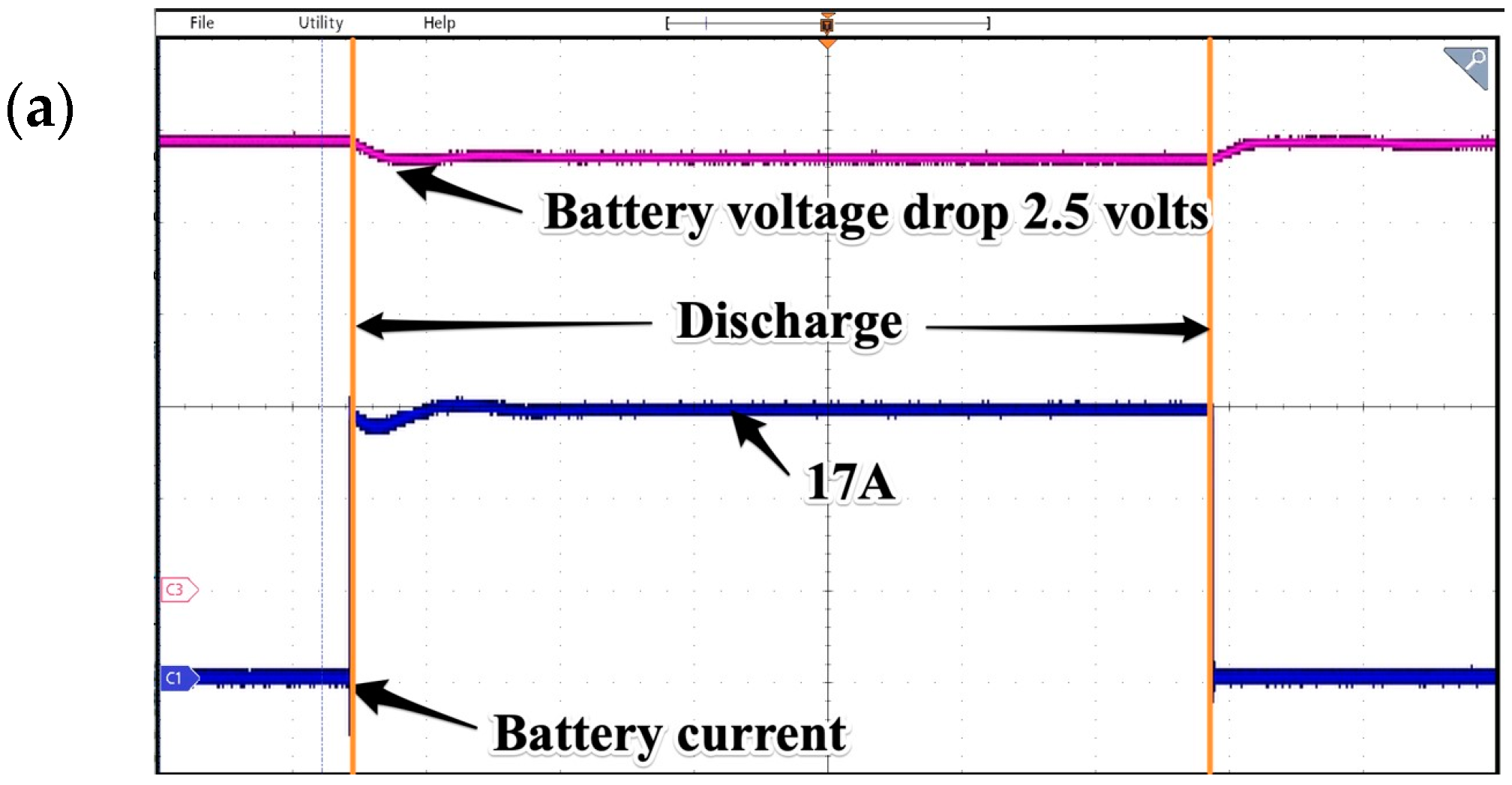
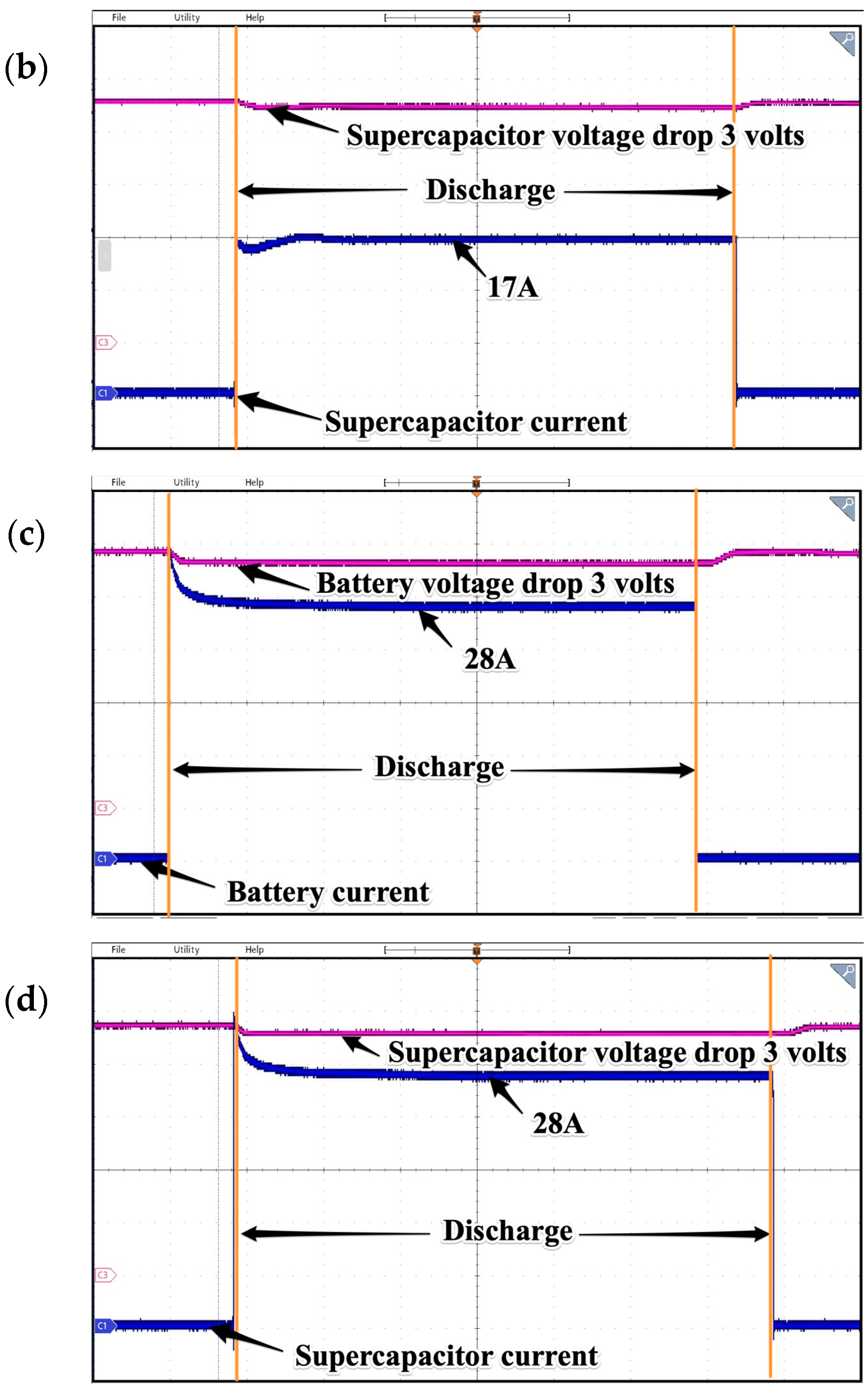
In the following tests, the influence of battery type (battery pack or supercapacitor) was investigated. The only source of power was battery or DAB converter. The tests were performed for two different resistive loads and the chosen results are presented in
Figure 24. For such loads in the given time, the visible voltage drop of both DC sources differs by 2 volts in favor of battery, which is natural due to a low energy density in the supercapacitor. In both cases, the experimental results showed the possibility of stable-feeding consumers for a relatively short time.
The difference between battery and supercapacitor banks shows up clearly in the prolonged discharging operation.
Supercapacitors are different from batteries because they do not rely solely on an electro-chemical process to function. The capacitors store potential energy electrostatically within their internal structures. To separate the positive and negative charges accumulating on the plates of each side, supercapacitors use a dielectric or insulator to separate the metallic covers. The most important advantage of supercapacitors is that, compared to electrochemical batteries, the electrical properties and capacity do not change much with aging. The most serious disadvantage of modern supercapacitors is a relatively fast self-discharge process that becomes more troublesome in low temperatures.
Another important feature is the faster process needed to charge and discharge supercapacitors compared to batteries, since they have higher power throughputs.
In terms of power density, electrochemical capacitors with high equivalent series resistance (ESR) values and time constants between one and 100 s are equal to batteries. The latest graphene-electrode designs in supercapacitors can get very close to electrolytic capacitors, which are 10 times more powerful than conventional batteries; moreover, they have time constants ranging from 0.1 s to 30 s. In turn, this led to the conclusion that supercapacitors are most suitable for short bursts of power, as evidenced by the tests that were conducted.
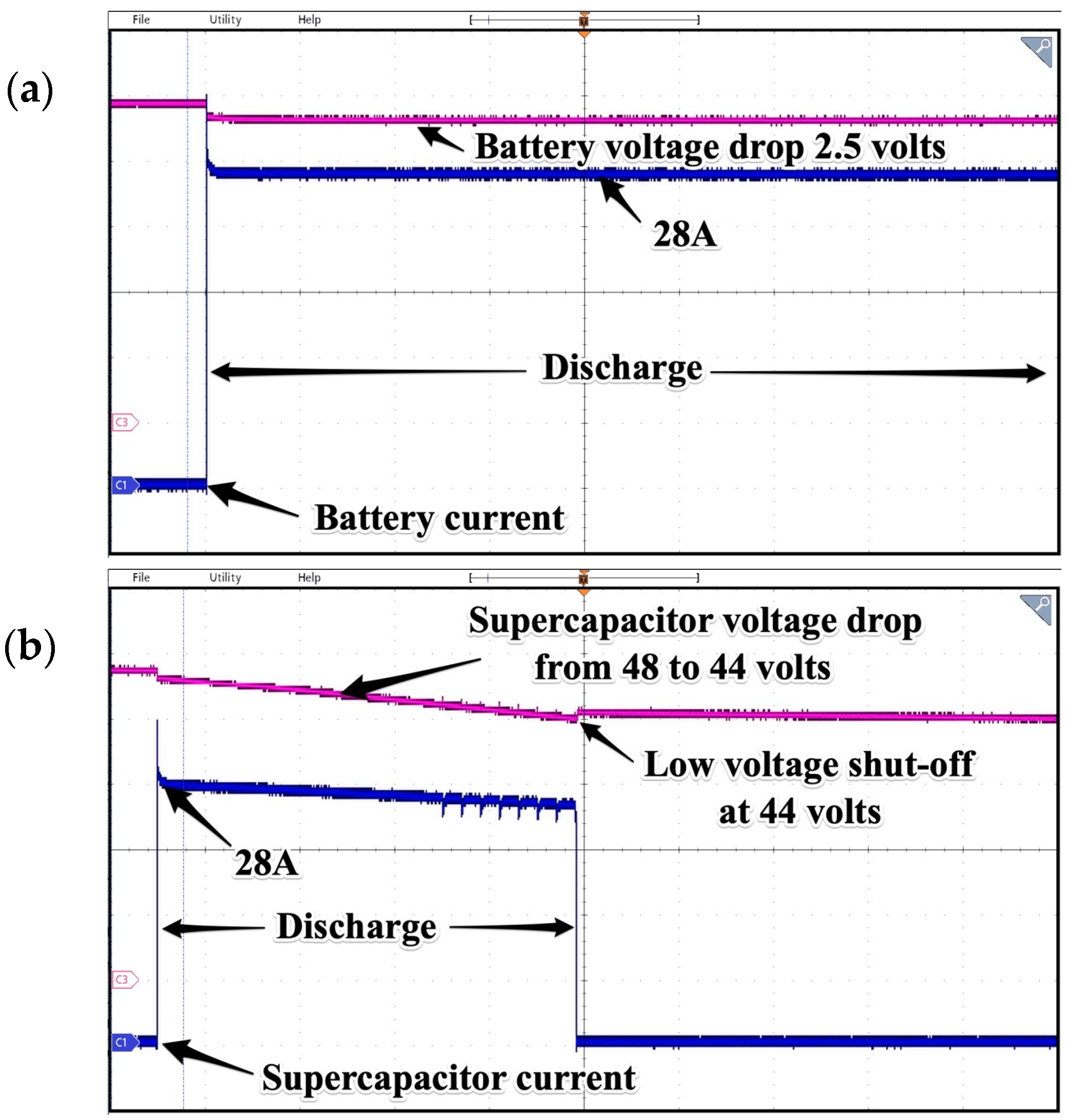
As it can be seen (see
Figure 25), the discharge process of a 165 F capacitor is rapid, and this feature clearly shows that a supercapacitor should be used as an intermediate voltage source mainly for harvesting peaks or as a buffer for the battery. Long-time operation should be performed with use of batteries, which have a higher energy density, thus some software means should be provided to ensure dynamic power distribution between voltage sources while in operation. It can be also considered as a form of prebuffer that decreases the number of charge/discharge operations on electrochemical batteries when frequent deep-cycling shortens their operational lifespan.
Next, a test involving the charging of batteries versus supercapacitor was performed to check the times needed for full charging. The bidirectional switches and DAB were set to charging mode. In charging mode, the buck-boost converter drops the voltage to level above the batteries’ nominal value. This setpoint can be changed due to needs because all parameters of controller are easily configurable. In the proposed solution, the system can work together with a batteries-management system or can be controlled by an external energy-management system by means of Modbus communication protocol.
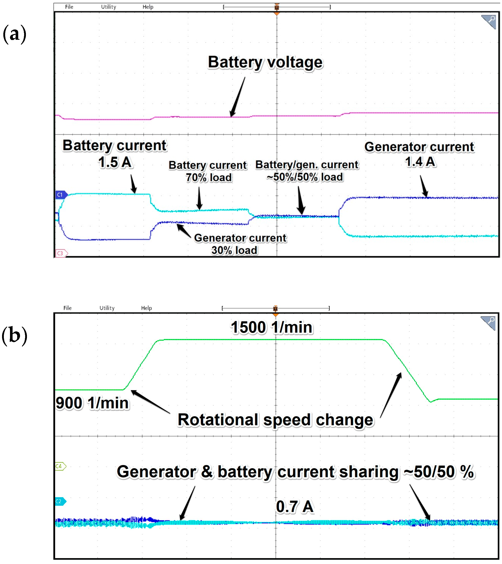
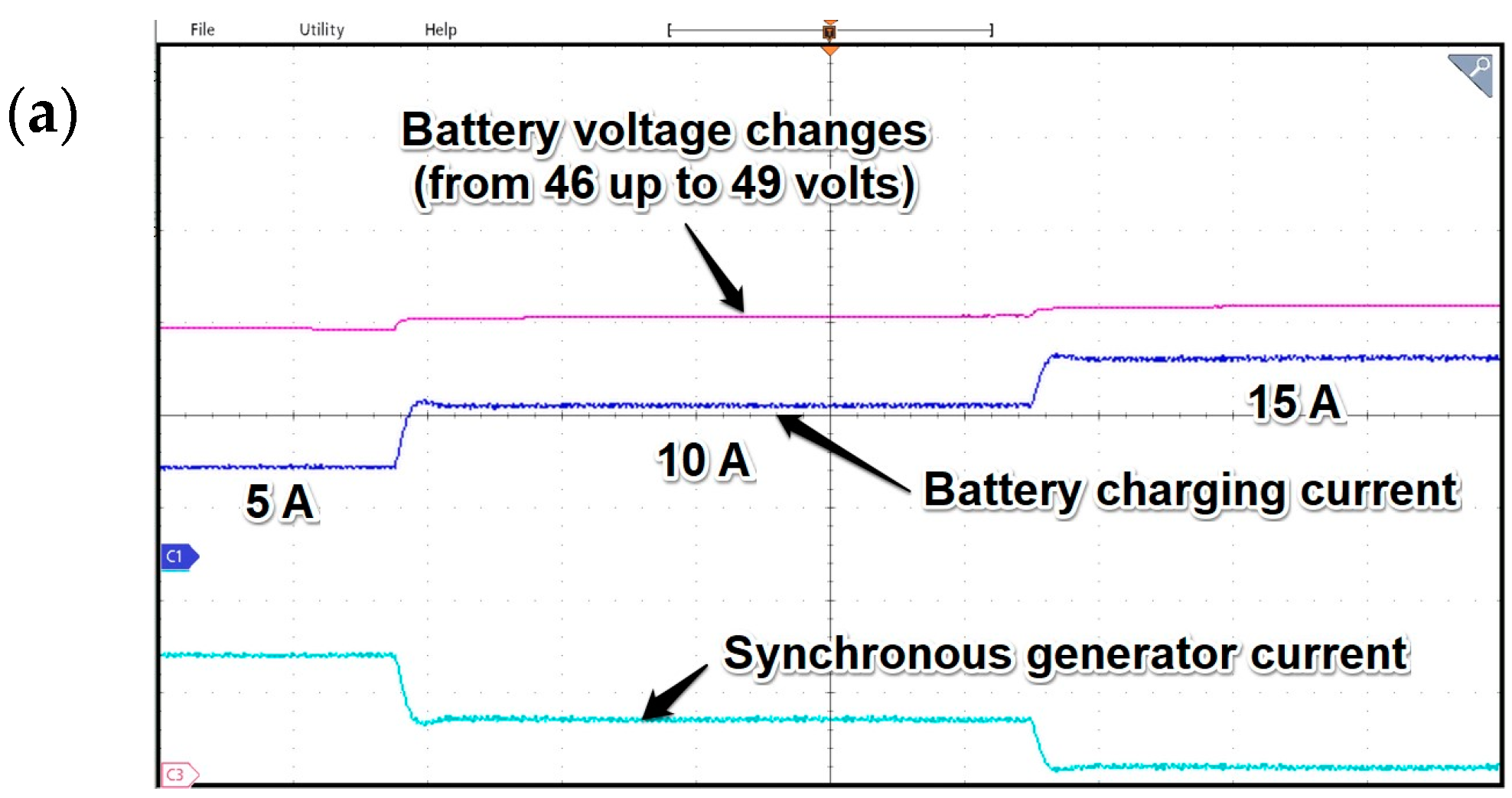
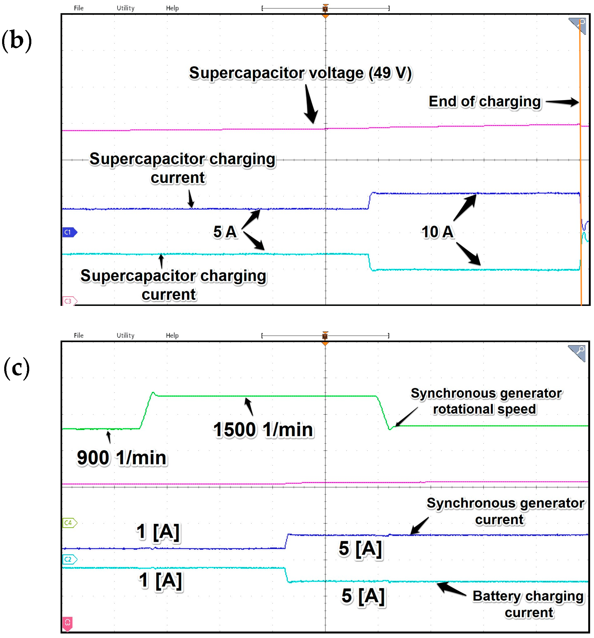
As it can be observed in
Figure 26a, the tests covered charging batteries with different currents; the values were gradually increased. Along with changes in charging current, the SESG current also increased. Its value was inversed just for clarification of the picture.
In
Figure 26b, there are waveforms of the supercapacitor voltage, charging current, and generator current. As expected, the charging process is very fast in this case, but the voltage value should be carefully controlled because overcharging the supercapacitor can lead to damage. The control system of charging process is set in a way that it controls the voltage in a 5 s period, and, in the case of signal error, there is a charging process enabled. This is manifested by current peaks appearing at regular intervals, as depicted in
Figure 25b. The maximum value of the charging current pulses is software-defined and can be changed according to the needs of the application. These current peaks clearly show one of the disadvantages of supercapacitors mentioned earlier, that is, the natural process of relatively quick self-discharge. The tests regarding charging processes proved that the same process as for discharging the supercapacitor works best as there is a buffer between energy storage (batteries) and DC grid. The charging process is quick and can be used for rapid electrical energy harvesting so these energy storage devices can work mainly as a buffer between the DC grid and the batteries bank.
The last subplot denoted as 26c presents influence of speed change on battery voltage and charging current along with SESG current. Thanks to field-oriented control, the direct current is not changing, which, notably, was one of the goals of presented application. As the results of subsequent tests proved, the change in active current isq of the generator is a noticeable difference during changes in speed; namely, for low RPMs, the current increases, while in the case of high speed, the active-current value drops. However, as long as the value of the DC bus voltage is stabilized in varying rotational-speed operating states, expected power distribution was preserved as well.


