1. Introduction
Nowadays, digital signal processors (DSPs) are widely used in many fields such as digital communications, video monitoring, machine control, unmanned aerial vehicles, instrumentation, and biomedicine [
1,
2,
3,
4,
5]. Compared with general-purpose microprocessors, DSPs adopt the Harvard structure that separates the program and data, and their instruction scheduling adopts pipeline operation, which can quickly complete a variety of digital signal processing algorithms [
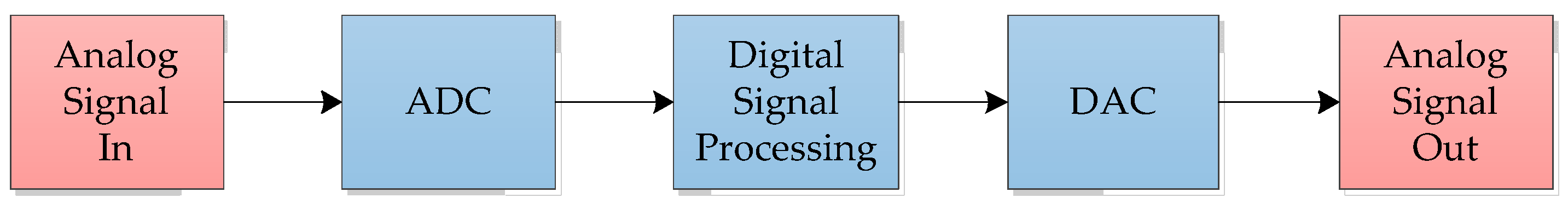
6]. A typical DSP system is shown in
Figure 1. The growing demand in the DSP market has seen the emergence of many high-performance DSPs in recent years such as AnySP [
7], Tensilica ConnX BBE64EP [
8], TI TMS320C6000 Series DSP [
9], YHFT-DSP [
10], SW processor [
11], and ARM Cortex-M4 family [
12]. As the study of computing parallelism becomes more and more deepened, the VLIW architecture together with the single-instruction-multiple-data (SIMD) vector unit has gradually become a typical representative of high-performance DSP architectures [
10,
13,
14,
15,
16]. The advantage of the vector unit over the scalar unit is that it can compute multiple data with one instruction, resulting in a significant reduction in the time required to execute corresponding programs [
17]. Vector DSPs are rich in hardware resources, while their architecture and instruction set differ from one DSP to another [
18]. To take full advantage of the hardware resources of each vector DSP, the compilation optimization according to the architecture characteristics of the vector DSP is very necessary [
19].
Compilation optimization for vector DSPs takes into account the hardware resources of the DSP, especially the register resources [
20]. Vector DSPs often have a lot of general-purpose registers in both scalar and vector data processing units, in order to adapt to the cases in which the computing of an algorithm can be vectorized or not. In particular, the configuration with both base address registers and offset registers provides more freedom in the optimization of loops. For example, YHFT’s vector DSP FT-7002 provides scalar data registers and vector data registers [
21]. Texas Instruments’ TMS320C6000 Series DSPs provide rich register resources such as accumulation register ACC, data register Dx, status register SR, and control register CR [
22]. An important part of compilation optimization is how to make the best use of multiple register resources [
23,
24].
Algorithm optimization has been one of the hot topics in current research [
25,
26,
27,
28,
29]. Scholars’ research on algorithm optimization can be divided into process optimization for the specific algorithms and general optimization for all algorithms [
30]. Because the compiler does not know the purpose of the program being compiled, the compilation optimization is mainly the generic optimization for all algorithms. Loop structures play a large part in the running time in many algorithms (e.g., digital signal processing algorithms, deep learning algorithms, neural network algorithms) [
31,
32,
33,
34,
35,
36], so loop optimization is an essential part of compilation optimization. The main approach of loop optimization is loop transformation. Loop transformation means that the compiler performs multiple loop reconstruction transformations to help improve the parallelism of loops in a program. Loop transformation mainly includes loop tiling [
37], loop skewing, loop unrolling [
38], and software pipelining. Loop unrolling is one of the most direct and effective approaches in loop transformation [
39], which improves the overall performance of the loop by increasing the efficiency of the parallel processing [
38]. Loop unrolling copies multiple loop bodies into one iteration and adjusts the array index and loop increment accordingly to ensure that the program runs correctly, which has the significant effect of reducing the loop overhead [
40]. Moreover, loop unrolling can increase the opportunities for other optimizations, such as common subexpression elimination, induction variable optimization, software pipelining, etc. [
41,
42]. And it is also an important part of optimizations such as vectorization and data prefetching [
43]. Overall, the benefits of loop unrolling include instruction-level parallelism, register locality, and hierarchical storage locality [
38].
The application of loop unrolling for vector architecture instruction sequences in the compilation optimization has been studied, but these studies are not flexible enough to deal with the allocation of register resources for vector DSPs, and there are cases where register resources for addressing are not fully used. In this paper, we use the conventional loop unrolling approach as a basis for extending the unrolling factor and increasing the scheduling range of instruction-level parallelism by making further use of the free register resources before register spilling happens. Based on the above ideas, this paper proposes a loop unrolling approach extending memory accessing (LUAEMA) that fully considers the free resources of registers and thus increases the unrolling factor.
The rest of this paper is as follows:
Section 2 provides related work on loop unrolling.
Section 3 illustrates the limitations of the conventional loop unrolling approach for vector DSPs and the model of LUAEMA.
Section 4 describes the algorithms in the LUAEMA, including the preparation algorithm for the unrolling factor, the unrolling factor algorithm, and the description of the code transformation for the original loop.
Section 5 analyzes the experimental results between the LUAEMA and the conventional loop unrolling approach. Finally, a few conclusions and directions for future studies are provided in
Section 6.
3. Framework and Model
3.1. Limitations of the Conventional Loop Unrolling Approach
Differences in the form of the loops can lead to different identified induction variables, even if the loops have the same arithmetic logic. Take Listing 1 and Listing 2, for example. Since both the conventional loop unrolling approach and the loop unrolling approach proposed in this paper are based on the consideration of the register resources in the hardware, the high-level language cannot fully explain the utilization of the register resources. Therefore, we take the instruction-level intermediate code as input. To illustrate the limitations of the conventional loop unrolling approach in register usage, the loops of Listing 1 and Listing 2 use instruction sequences internally, while the loop control section retains the high-level language format.
There are two types of variables that are special for addressing in a loop, address variables and offset variables. These two types of variables refer to address registers (Rx) and offset registers (Ry) in instruction-level intermediate code. The conventional loop unrolling approach determines whether the address registers or the offset registers need to be unrolled in the intermediate code based on the identification of induction variables.
The arithmetic logic of the two loops shown in Listing 1 and Listing 2 is to take out each element of ARa in turn, add 1, and put them into ARb. The induction variables identified in the conventional loop unrolling approach are different depending on the different forms of a loop. The induction variables of the loop in Listing 1 are Ri and Ork. And the induction variables of the loop in Listing 2 can be identified as Ri, Ara, and ARb.
| Listing 1. The loop whose inductive variables are Ri and ORk. |
Mov 0, ORk
do Ri = 1, Rn
Load ARb[ORk], Rb
Add 1, Rb, Ra
Store Ra, ARa[ORk]
Add 1, ORk, ORk
enddo |
| Listing 2. The loop whose inductive variables are Ri, ARa, and ARb. |
Mov 0, ORk
do Ri = 1, Rn
Load ARb[ORk], Rb
Add 1, Rb, Ra
Store Ra, ARa[ORk]
Add 1, ARa, ARa
Add 1, ARb, ARb
enddo |
Before unrolling the loop, it is necessary to identify whether the instruction operands within the loop need to be created unrolling copies. The variables that require creating unrolling copies identified by the conventional loop unrolling approach are made up of inductive variables and loop variations. In Listing 1, they are Ri, ORk, Ra, and Rb, while in Listing 2, these variables are Ri, ARa, ARb, Ra, and Rb. Taking Ra as an example, its copies are written as Ra_1, Ra_2, and so on.
For the purpose of showing the limits of the conventional loop unrolling approach when using address registers and offset registers, the following loop unrolling example assumes that there are no restrictions on other types of register resources. This means that the need for using other types of register resources during loop unrolling will be fully satisfied and it is only guaranteed to consider the full use of the free resources in address registers or offset registers.
Let the total number of address registers be e and the total number of offset registers be f on the DSP hardware. Before the loop unrolling process, both Listing 1 and Listing 2 have used two address registers (ARa and ARb) and one offset register (ORk). Because Listing 1’s set of variables that need to be created unrolling copies contains ORk, the unrolling factor (UF) of the loop shown in Listing 1 is set to f in order to fully use the offset registers. Similarly, the unrolling factor of the loop shown in Listing 2 is set to e/2. Listing 1 and Listing 2 are translated into Listing 3 and Listing 4, respectively, after being processed by the conventional loop unrolling approach.
| Listing 3. Listing 1 after being processed by the conventional loop unrolling approach. |
Mov f, UF
Mov 0, ORk
Add 1, ORk, ORk_1
……
do Ri = 1, Rn/UF
Load ARb[ORk], Rb
Load ARb[ORk_1], Rb_1
……
Add 1, Rb, Ra
Add 1, Rb_1, Ra_1
……
Store Ra, ARa[ORk]
Store Ra_1, ARa[ORk_1]
……
Add UF, ORk, ORk
Add UF, ORk_1, ORk_1
……
enddo |
| Listing 4. Listing 2 after being processed by the conventional loop unrolling approach. |
Mov e/2, UF
Mov 0, ORk
Add 1, ARa, ARa_1
……
Add 1, ARb, ARb_1
……
do Ri = 1, Rn/UF
Load ARb[ORk], Rb
Load ARb_1[ORk], Rb_1
……
Add 1, Rb, Ra
Add 1, Rb_1, Ra_1
……
Store Ra, ARa[ORk]
Store Ra_1, ARa_1[ORk]
……
Add UF, ARa, ARa
Add UF, ARa_1, ARa_1
……
Add UF, ARb, ARb
Add UF, ARb_1, ARb_1
……
enddo |
When the UF of Listing 3 is equal to the UF of Listing 4, the number of self-incrementing instructions in Listing 4 is twice that in Listing 3. This means that although there are different ways to write the same loop logic, the conventional loop unrolling approach does not have the ability to change the form of the loop, which may lead to redundant code lines within the loop. When the loop is designed in the form of Listing 2, the conventional loop unrolling approach can only process it into the form of Listing 4, ignoring the possibility of further analyzing the types of the different variables to obtain a more concise loop form, as shown in Listing 3.
The hardware resources provided by the processor should be fully considered during loop unrolling in the vector DSP. The induction variables of the loop shown in Listing 3 include ORk, and the address registers ARa and ARb are used as loop invariants, so the free resources of Rx are not fully used in loop unrolling. This will result in the resources in Rx appearing to be free when the loop is running. Similarly, the loop shown in Listing 4 suffers from the problem of under-use of free resources in Ry.
In order to solve the two problems of neglecting the number of instructions in the loop which can be reduced and not fully using the free resources of a certain register type in the conventional loop unrolling approach, this paper proposes an improved instruction-level loop unrolling approach that unrolls both address registers and offset registers at the same time to further improve loop optimization and increase the scheduling range of instruction-level parallelism. This approach makes full use of the two kinds of register resources, Rx and Ry, to further increase the unrolling factor when the general registers are sufficient. And it can also be used flexibly to reduce the number of instructions in the loop according to the unrolling situation of Rx and Ry.
3.2. The Mathematical Model for LUAEMA
ORk belonging to Ry in the loop shown in Listing 3 is the loop variation (the variable that is needed to create the unrolling copies in loop unrolling) in the loop unrolling process. ARa and ARb belonging to Rx are the loop invariants. This is the opposite case for the loop shown in Listing 4, where ARa and ARb are the loop variations in the loop unrolling process and ORk is the loop invariant. The two loop forms with the same arithmetic logic can only make use of the free resources of one register in Rx or Ry after loop unrolling, which will lead to the situation that the resources of the other register cannot be fully used. Therefore, this section considers whether it is possible to have a loop unrolling approach that can use the free resources of both types of registers, Rx and Ry, at the same time and proposes a loop unrolling processing model extending memory accessing that unrolls both Rx and Ry. The basic principle of the model is as follows.
3.2.1. Obtain the Set of Variables Aur
Loop unrolling needs to obtain the set of variables Aur that need to create unrolling copies in the loop before determining the unrolling factor. Aur consists mainly of induction variables and loop variations in the conventional loop unrolling approach. The induction variables for the loop shown in Listing 1 are Ri and ORk, and the induction variables for the loop shown in Listing 2 are Ri, ARa, and ARb. The induction variables for both loops include Ri, since Ri is the loop control induction variable, and its main role is to guarantee the loop times. The main purpose of the induction variables other than Ri is to ensure that it is correct when accessing memory by address, except that the loop shown in Listing 1 uses Ry to access the memory correctly, and the loop shown in Listing 2 uses Rx. This would ignore the fact that both Rx and Ry can be unrolled. In order to satisfy that Rx and Ry are used in loop unrolling, this model adds the loop invariants belonging to Rx or Ry in the original loop to Aur.
3.2.2. Calculate the Unrolling Factor
The calculation of the unrolling factor can be conducted in three steps: the classification of Aur; calculation of UFx, UFy, UFxy, and UFR; and acquirement of the final unrolling factor UF. This is performed as follows:
(1) Analyze
Aur and classify all the variables in
Aur into two—
AurXY and
AurOther—according to whether they belong to
Rx or
Ry:
AurXY contains variables related to the
Rx and
Ry of
Aur:
AurOther contains other variables in
Aur that are not related to
Rx and
Ry, with scalar general registers (
SRs), vector general registers (
VRs), and so on:
AurX and AurY in Equation (2) represent the sets of variables that need to create unrolling copies of Rx and Ry in the original loop. Similarly, AurSR and AurVR in Equation (3) denote the sets of variables belonging to scalar general registers and vector general registers that need to create unrolling copies in the original loop.
(2) Calculate unrolling factors for Rx and Ry. The unrolling factor of Rx is set to UFx, and the unrolling factor of Ry is set to UFy. The equations for the unrolling factors are as follows:
The initial value of
UFx is given by the following:
where |...| refers to the total number of variables in the set,
numX represents the total number of
Rx in the vector DSP, and
AusingX refers to the
Rx variables that are active before or after the original loop. Similarly, the initial value of
UFx is given by the following:
After obtaining the initial values of
UFx and
UFy, multiply them together to obtain
UFxy that
Rx and
Ry can provide for loop unrolling.
According to Equations (4) and (5), calculate the maximum unrolling times that can be provided by each register type that does not belong to
Rx and
Ry such as scalar general registers and vector general registers. Compare them and select the minimum value as
UFR:
(3) Compare
UFxy with
UFR. When
UFxy is less than
UFR, it means that the maximum unrolling times that can be provided by
AurXY are not limited by the other registers. This situation achieves the effect that the free resources of
Rx and
Ry are fully used. Therefore, the final unrolling factor
UF is given by the following:
Conversely, when
UFxy is greater than
UFR, it indicates that the full use of
Rx and
Ry leads to passive measures of register protection for other types of registers, which is not in line with the original intention of loop unrolling in this paper. Therefore, it is necessary to round down the smaller values of
UFx or
UFy. The update in
UFx or
UFy is given by the following:
Update
UFxy using Equation (8) after processing
UFx or
UFy according to Equation (9). The updated
UFxy must be within the range of
Then, the
UF is given by the following:
When UFxy is equal to UFR, it indicates that the full use of the free resources of Rx and Ry is accompanied by the full use of the free resources from one of the other register types. The final unrolling factor UF in this case can be derived by Equation (8) or Equation (11).
3.2.3. Update the Identified Set of Induction Variables
After calculating UFx and UFy, judge whether the identified set of induction variables needs to be updated. Calculate the total number of new instructions that need to be generated for loop unrolling when either Rx or Ry is used as the induction variable and compare to find out which one generates fewer new instructions. If the register type resulting from the comparison is the same as the register type identified in the origin loop as the induction variable, there is no need to update the set of induction variables. If different, it is necessary to replace the variables belonging to Rx or Ry in the set of induction variables with the register type derived from the comparison and replace the corresponding code in the loop body during code transformation.
3.2.4. Initialize Unrolling Copies for Rx and Ry
In code transformation, initialize (UFx − 1) copies for Rx that need to be unrolled in the loop and initialize (UFy − 1) copies for Ry that need to be unrolled in the loop.
Some rules should be followed when initializing unrolling copies of
Rx and
Ry. When initializing copies of
Rx, the following rule must be obeyed:
where
X refers to a certain variable belonging to
Rx that needs to create unrolling copies;
X_1 is the next unrolling copy that needs to be created for
X; and
L is the data volume that can be computed in one iteration of the origin loop, which is typically 1 in scalar processors but depends on the architecture of the processor in vector processors.
When initializing copies of
Ry, the following rule must be obeyed:
where
Y refers to a certain variable belonging to
Ry that needs to create unrolling copies;
Y_1 is the next unrolling copy that needs to be created for
Y.
The code example of Listing 2 after the LUAEMA is shown in Listing 5.
| Listing 5. Listing 2 after being processed by the LUAEMA. |
Mov e/2, UFx
Mov f, UFy
Mul UFx, UFy, UF
Mov 0, ORk
Add 1, ORk, ORk_1
……
Add UFy, ARa, ARa_1
……
Add UFy, ARb, ARb_1
……
do Ri = 1, Rn/UF
Load ARb[ORk], Rb
Load ARb[ORk_1], Rb_1
……
Load ARb_1[ORk], Rb_f
……
Add 1, Rb, Ra
Add 1, Rb_1, Ra_1
……
Store Ra, ARa[ORk]
Store Ra_1, ARa [ORk_1]
……
Store Ra_f, ARa_1[ORk]
……
Add UF, ORk, ORk
Add UF, ORk_1, ORk_1
……
enddo |
The LUAEMA includes the initialization of unrolling copies about ARa and ARb and also the initialization of unrolling copies about ORk. Compared to the loop shown in Listing 4, which performed the conventional loop unrolling approach of Listing 2, the LUAEMA replaces self-increasing instructions for ARa and ARb with self-increasing instructions for ORk in the loop, which means that the induction variables are updated—the set of induction variables consisting of Ri, Ara, and ARb is updated to the set of induction variables consisting of Ri and ORk. This is due to the fact that the total number of instructions generated by Rx and Ry as induction variables was compared after the computation of the unrolling factor was completed, and the register type with the smaller total number between them was selected as the register type with self-increasing instructions for the induction variables within the loop.
The output of the LUAEMA is the optimized instruction-level intermediate code. This intermediate code has a large number of instructions in the loop, so the scheduling domains available for VLIW to choose from during code scheduling are large. One major advantage of the LUAEMA is its ability to increase the parallel scheduling domains of instructions, which is reflected in VLIW. The very long instruction word (VLIW) of the vector processor can be filled with both scalar instructions and vector instructions simultaneously. For a loop, the instructions that are involved in its computation (such as the memory access instructions in Listing 5) are vector instructions. In contrast, the self-increasing instructions that control the loop iterations and correct memory access in the loop (such as the self-increasing instruction of ORk in Listing 5) are oriented towards data, so they can only be used with scalar instructions. Loop unrolling increases the number of instructions for scalars and vectors. The increased number of instructions can provide VLIW with more instruction sequences to choose from when filling instruction words, thereby ensuring that the instruction words are fully filled multiple times during the execution of the loop, improving the efficiency of the instruction sequences.
4. Algorithms
4.1. Identification Algorithm of Variables That Need to Create Unrolling Copies
Each register in a loop can be classified as a loop variant or a loop invariant based on whether or not its value is changed in the loop. When performing the conventional loop unrolling approach, the values of loop invariants are unchanged, and the loop variations need to create unrolling copies based on the unrolling factor. Therefore, finding out the variables that need to create unrolling copies in a loop is essential for loop unrolling processing.
The conventional loop unrolling approach identifies Rx or Ry when identifying the variables that need to create unrolling copies. In order to satisfy the condition of creating unrolling copies for both Rx and Ry proposed in this paper, it is necessary to judge Rx and Ry again based on the identification of the set of variables that needs to create unrolling copies by the conventional loop unrolling approach, to arrive at the final set of variables Aur that needs to create unrolling copies.
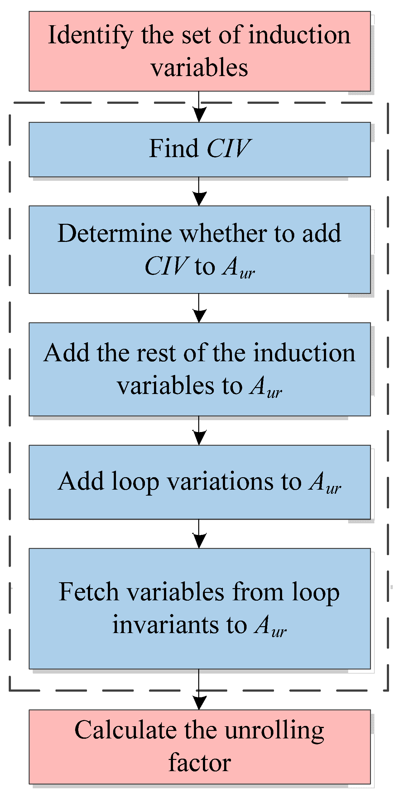
A detailed flow chart is shown in the dashed box in
Figure 2.
The implementation can be found in Algorithm 1.
| Algorithm 1. Identification algorithm of variables that need to create unrolling copies |
| Input: the set of induction variables(IVs); LCVs; LINVs; definition-use chain derived from data |
Output: Aur; Type- (1)
CIVTimes = getCIVTimes() - (2)
if CIVTimes > 2 then - (3)
Aur.insert(CIV) - (4)
endif - (5)
for each IV in IVs do - (6)
if IV != CIV then - (7)
Aur.insert(IV) - (8)
endif - (9)
2ndfor - (10)
LCVs = getLCVs() - (11)
Aur.insert(LCVs) - (12)
if Aur.include(Rx) then - (13)
Type = Ry - (14)
else - (15)
Type = Rx - (16)
endif - (17)
for each LINV in LINVs do - (18)
if LINV.type = Type then - (19)
Aur.insert(LINV) - (20)
LINVs.clear(LINV) - (21)
endif - (22)
endfor
|
The content note for Algorithm 1:
- (1)
LCVs is the set of loop variants in the loop.
- (2)
LINVs is the set of loop invariants in the loop.
- (3)
getCIVTimes() is to analyze the times that the loop control induction variable (CIV, i.e., Ri in Listing 1) has been used during the loop.
- (4)
Aur is the set of variables that needs to create unrolling copies in the loop.
- (5)
getLCVs() is to obtain the set of loop variations.
- (6)
Type is Rx or Ry that is not included in the induction variables of the origin loop but can become induction variables in loop unrolling. Induction variables in the conventional loop unrolling approach contain Rx or Ry, depending on the form of the loop. Instead of determining which one of Rx or Ry is the induction variable based on the loop form, the LUAEMA compares the total number of new instructions that need to be generated after Rx or Ry is a part of the induction variables.
Unlike the identification algorithm of variables that need to create unrolling copies in the conventional loop unrolling approach, the algorithm proposed in this section takes a certain type of register that would otherwise be part of the loop invariants out of the set of loop invariants and puts it into Aur and provides the Type for subsequent updates to the set of induction variables.
4.2. Algorithm for Calculating Unrolling Factor
After determining which variables in the loop need to create unrolling copies, the conventional loop unrolling approach needs to analyze the register types of variables in Aur, calculate the total number of free registers in each register type in the loop, determining the unrolling factor for each register type, and then derive the unrolling factor of the loop.
The unrolling factor algorithm for the LUAEMA divides the registers into two groups, registers for memory access (Rx and Ry) and other registers (VR, SR, etc.), and sets the unrolling factors UFx and UFy for Rx and Ry, respectively. The product of the two unrolling factors is the maximum unrolling factor UFxy that memory access registers can provide.
Other registers are categorized by the register type, and the unrolling factors that the different register types can provide are calculated from the total number of free resources in the different register types. The unrolling factors that are available for each register type are compared and the smallest value is derived as the unrolling factor UFR that other registers can provide.
The UFxy and UFR are compared and calculated to obtain the final unrolling factor UF.
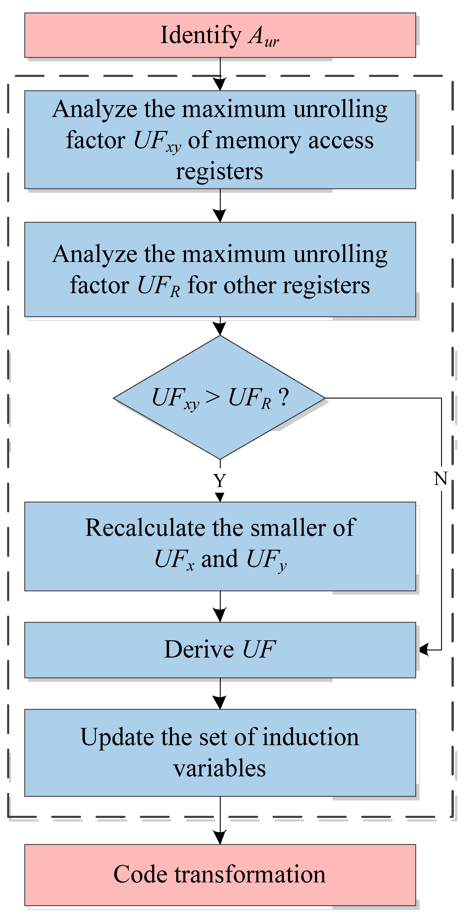
A flow chart of the unrolling factor algorithm for the LUAEMA is shown in the dashed box in
Figure 3.
The process of realization is described in Algorithm 2.
| Algorithm 2. The algorithm for calculating the loop unrolling factor |
Input: LINVs; Aur; LiveVs; numReg
Output: UFx; UFy; UF; newIVs- (1)
for each Regtype in RegTypes do - (2)
numUnroll = Aur(RegType).size - (3)
numFree = numReg(RegType)- LINVs(RegType).size- LiveVs(RegType).size - (4)
factor(RegType) = numFree / numUnroll - (5)
endfor - (6)
UFx = factor(Rx) - (7)
delete factor(Rx) - (8)
UFy = factor(Ry) - (9)
delete factor(Ry) - (10)
UFxy = UFx × UFy - (11)
UFR = min{factor(SR), factor(VR); …} - (12)
if UFxy > UFR then - (13)
min{UFx, UFy} = UFR / max{UFx, UFy} + 1 - (14)
UF = UFR - (15)
else - (16)
UF = UFxy - (17)
endif - (18)
getNewIVs()
|
This algorithm contains the following main elements:
- (1)
numUnroll is the number of variables that need to create unrolling copies in each register type.
- (2)
Aur is the set of variables that needs to create unrolling copies in the loop.
- (3)
numFree is the number of free resources for each register type. This value is obtained by taking the total number of resources of the register type, numReg, and subtracting the number of loop invariants of this class in the loop, LINVs(RegType).size, and subtracting the number of this register type that are active outside the loop, LiveVs(RegType).size.
- (4)
LINVs is the set of loop invariants in the loop.
- (5)
LiveVs is the set of registers that are not used in the loop but are still active outside the loop.
- (6)
factor is the function to obtain the maximum unrolling factor that each register type can provide for loop unrolling processing. This value is obtained by dividing numFree by numUnroll.
- (7)
UFx is the maximum unrolling factor determined by Rx.
- (8)
UFy is the maximum unrolling factor determined by Ry.
- (9)
UFR is the minimum of the maximum unrolling factors for each register type except Rx and Ry.
- (10)
UF is the final unrolling factor.
- (11)
getNewIVs() is used to update the set of IVs. The process is mainly performed to obtain the smaller value of the product of UFx and Aur(Rx).size and the product of UFy and Aur(Ry).size, then determine whether the register type that the smaller value belongs to is the same as the register type recorded by the Type. If yes, there is no need to update the IVs. If no, the registers belonging to the Type in the set of registers that need to create unrolling copies are put into the IVs, and the Rx or Ry in the IVs that do not belong to the Type are moved out.
Unlike the conventional algorithm for calculating the unrolling factor, the unrolling factor algorithm in this section fully analyzes the register resources of vector DSP and its characteristics and targets to improve the conventional loop unrolling approach to make it more suitable for the hardware architecture of vector DSP. More specifically, the unrolling factor algorithm of the conventional loop unrolling approach restricted by both Rx and Ry is improved to the algorithm that treats Rx and Ry as the same register type, and the flexible updating of the self-increasing instructions for Rx or Ry as induction variables in the loop is taken into account prior to code transformation.
4.3. Code Transformation
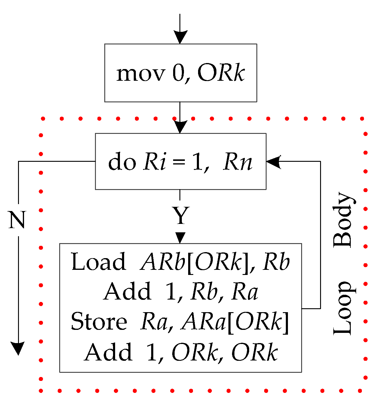
Code transformation of the origin loop is required after determining the unrolling factor. The LUAEMA takes instruction-level intermediate code as input, and the code has been divided into basic blocks. The flow graph for the loop shown in Listing 1 is shown in
Figure 4.
The three basic blocks from top to bottom in
Figure 4 are named according to the function of the different basic blocks: the first basic block is the initialization basic block; the second basic block is the loop control basic block; and the third basic block is the loop calculation basic block. The number of basic blocks involved in the loop will be five after the loop has been processed by the LUAEMA, including the three basic blocks of the original loop, as shown in
Figure 4, and the two new basic blocks added to ensure the correctness of the program after the loop unrolling process—the recovery basic block and the tail processing basic block. Therefore, this section divides the code transformation into five parts in terms of the different basic blocks involved in loop unrolling:
The first part is the initialization basic block, which is generally located in the last basic block before entering the loop. The code transformation for this basic block is used to add initialization instructions for UFx, UFy, and the final unrolling factor UF, to add an initialization instruction for the total number that the loop can calculate by iterating once, and to add the instructions that initialize the unrolling copies of Rx and Ry according to the unrolling factors of UFx and UFy (following the initialization rules of Equations (12) and (13)).
The second part is the loop control basic block. The code transformation in this basic block mainly replaces the variables that represent the data volume that can be calculated in each iteration of the loop.
The third part is the loop calculation basic block. The code transformation of this basic block needs to traverse each of the instructions in turn. If one of the variables in the instruction is in the set of variables that needs to create unrolling copies, the instructions for its unrolling copies are added after this instruction. The instructions in this basic block, other than the calculation-related instructions, are the self-increasing instructions for the induction variables. The code transformation of these instructions needs to judge and update the self-increasing instructions of the induction variables belonging to Rx and Ry—firstly, according to getNewIVs() in the unrolling factor algorithm to determine which one of Rx and Ry determines the self-increasing instructions, and then adding the self-incrementing instructions for the unrolling copies of the induction variables using either UFx or UFy.
The fourth part is the recovery basic block for Rx and Ry. The loop calculation basic block may have substitutions for the induction variables, e.g., the induction variables in the loop shown in Listing 2 contain Rx, but after being processing by the LUAEMA (i.e., Listing 5), the induction variables for addressing are changed to Ry. To ensure that the code runs correctly, the values of the induction variables belonging to Rx and Ry need to be modified in accordance with the loop form of the origin loop to fit the subsequent tail processing basic block.
The fifth part is the tail processing basic block. The data volume that can be calculated in one iteration of the unrolled loop is the multiplication result of the unrolling factor and the data volume calculated in one iteration of the original loop. If the total data volume of the loop cannot be evenly divisible by the data volume in one iteration after the LUAEMA, there are two ways to handle it. One is that the total data volume is increased to the point where it can be exactly divided by the data volume in one iteration of the loop, which can lead to the generation of invalid data. The other is to split the total data volume into the largest number that can be divided by the data volume calculated in one iteration and the tail number; the tail number part is calculated by adding the tail processing basic block. The second processing method is used here—the original loop code is added as the tail processing basic block at the end of the unrolling loop.
5. Case Study
In order to demonstrate the processing effect of the LUAEMA, we built a vector DSP processor model based on multiple register types. The model is an SIMD architecture, where vectors are set to calculate eight pieces of data at a time. The register resources can be divided into the following:
Sixty-four vector registers (VRs), each of them can calculate eight pieces of data and have vector processing units and instructions to support this register type;
Sixty-four scalar registers (Rs), each of them can calculate one piece of data;
Eight address registers (Rx) to hold the contents of the base addresses;
Eight offset registers (Ry) to hold the offset of the base addresses.
The vector instruction-level intermediate code of Listing 1 is processed on the basis of this model using the approach proposed in this paper for loop unrolling.
Table 1 shows the instruction-level intermediate code of Listing 1.
The instruction-level intermediate code in
Table 1 differs from the scalar loop in Listing 1 in that the instruction-level intermediate code uses vector instructions. However, the control instructions for the vector loop are still determined by the SR.
According to the definition of inductive variables, the inductive variables (
IVs) for
Table 1 are
Ri (derived by S13) and
ORi (derived by S14), where
Ri controls the loop times. The analysis of BasicBlock2 yields
Ri as the loop control induction variable (
CIV).
First, the variables that need to create unrolling copies are identified. The first step is to analyze the times that the CIV (Ri) has been used in BasicBlock2 and BasicBlock3. Ri is the source operand in S3 and S13, so Ri has been used two times, and there is no need to create its unrolling copies. The other inductive variable (ORi) is placed into the Aur. The loop variations of BasicBlock3 are VRx, VRz, Ri, and ORi, so VRx and VRz are placed into the Aur. The loop invariants are ARx, ARz, and VRy, and since they contain Rx (ARx, ARz) that need to be unrolled, ARx and ARz are cleared from the loop invariants and placed into the Aur. The updated loop invariant is VRy. Finally, the Aur contains ORi, VRx, VRz, ARx, and ARz. And the value of the Type is Rx.
The intermediate code in
Table 1 is processed in the algorithm for calculating the unrolling factor: Grouping the
Aur by the register types, the number of
numUnroll corresponds to 2, 0, 2, and 1 for
VR,
R,
Rx, and
Ry, respectively. The
numAll for
VR,
R,
Rx, and
Ry is 64, 64, 8, and 8, respectively. The number of loop invariants (
LINVs) for
VR,
R,
Rx, and
Ry is 1, 0, 0, and 0.
LiveVs need to be determined based on the number of each register type used when running to the loop head (S5) and loop tail (runs to BasicBlock4); the number of
LiveVs for
VR,
R,
Rx, and
Ry can be set to 20, 30, 3, and 0.
From the above information, the number of numFree for VR, R, Rx, and Ry is 43, 34, 5, and 8, respectively, so their factor is 21, 30, 2, and 8. Then, the value of UFx is 2 and the value of UFy is 8. UFx and UFy are removed from factors, which now only contains the factors of VR and R. The minimum value in all factors is compared with the product of UFx and UFy, i.e., 21 > 2 × 8. The final unrolling factor UF is 16. Finally, we compare the product of UFx and the number of variables (ARx, ARz) needed to create the unrolling copies for Rx (2 × 2) with the product of UFy and the number of variables needed to create the unrolling copies for Ry (ORi) (8 × 1), to obtain the Type. Rx is determined as the register type to be self-incremented in the loop.
After obtaining UFx, UFy, and UF, the code transformation of the original code is started. The following is the description of the transformation of each basic block:
- (1)
Firstly, there is the initialization basic block, which is BasicBlock1 in
Table 1. The definitions of
UFx,
UFy and
UF are added, the data volume in one iteration of the loop is updated, and instructions for initializing the unrolling copies that need to be newly created in
Rx and
Ry are added. The BasicBlock1 processed by the LUAEMA is shown in
Table 2.
In
Table 2, S1 is the definition of
UFx, S2 is the definition of
UFy, and S3 is the definition of
UF; S6 is the update instruction for the data volume in one iterate of the loop. S9 and S10 are the instructions for initializing the unrolling copies that need to be newly created in
Rx. S12 to S18 are the instructions for initializing the unrolling copies that need to be newly created in
Ry.
- (2)
The loop control basic block, i.e., BasicBlock2.
Rstep is updated to the data volume in one iterate of the loop after the LUAEMA,
RunrollingStep. BasicBlock2 processed by the LUAEMA is shown in
Table 3.
- (3)
The loop calculation basic block, i.e., BasicBlock3. It is divided into two parts: the first is to add the calculation instructions in the loop by
Aur and the unrolling factor; the second is to add or update the self-increment instructions of the inductive variables. BasicBlock3 processed by the LUAEMA is shown in
Table 4.
S1 to S48 are the additions of memory access and calculation instructions in the loop. S50 to S53 are the update instructions for the inductive variables. In the original loop, ORi is the inductive variable, but it is updated here to be the self-increment instructions for ARx and ARz.
- (4)
The recovery basic block for
Rx and
Ry. This basic block does not exist in the original code. Before the loop unrolling process, the
Rx of the loop in
Table 1 are the loop invariants and the
Ry are the inductive variables, whereas after the loop unrolling to further improve the performance, the
Rx are changed to the inductive variables and the
Ry are the loop invariants. To handle data in
Rsum that are not evenly divided by
RunrollingStep,
Rx and
Ry used in the loop need to be changed to the values of the original loop format, so this basic block needs to be added. The basic block is placed between BasicBlock3 and BasicBlock4, as shown in
Table 5.
- (5)
The tail processing basic block. The basic block of
Table 5 has restored
Rx and
Ry used in the loop to their values at the corresponding runtime in the intermediate code of
Table 1. The instructions for BasicBlock2 and BasicBlock3 in
Table 1 are placed after the basic block of
Table 5.
The LUAEMA has completed the processing of the intermediate code in
Table 1. Unlike the conventional loop expansion approach, the unrolling factor of the loop is greatly improved, and the number of instructions in the loop is reduced. The conventional loop unrolling approach for the intermediate code in
Table 1 yields a value of 8 in the calculation of the unrolling factor, whereas the LUAEMA’s unrolling factor is 16. And the LUAEMA reduces the number of instructions in the loop by replacing the self-increment instructions of the inductive variables in the loop under the same unrolling factor, which further improves the performance of the loop.
6. Performance Analysis
In order to test the effect of the LUAEMA in this paper, the YHFT high-performance DSP FT-M7002 was selected as the hardware platform for testing.
The FT-M7002 is a DSP-based 40 nm process chip with a main frequency of 1 GHz, which has two DSP cores and one CPU core. Each DSP core has 64 KB L1D Cache and 32 KB L1P Cache with 32 KB of in-chip scalar space and 768 KB of in-chip vector space. The global shared Cache is 2 MB, and there is up to 32 GB of synchronous Dynamic Random Access Memory (DDR) outside the core [
50].
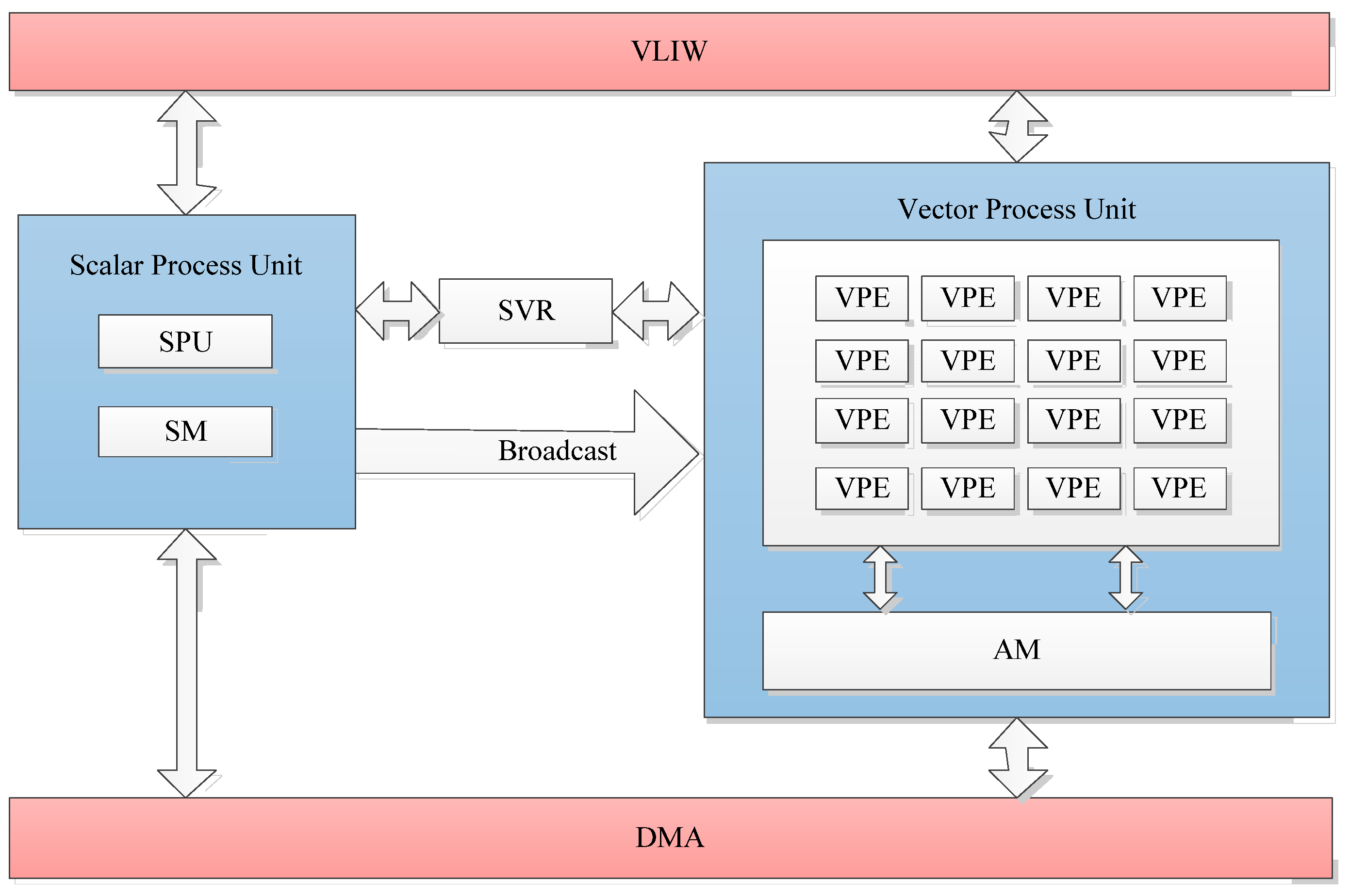
The DSP core of the FT-M7002 is based on the VLIW structure, which contains a five-outflow scalar process unit (SPU) and a six-outflow vector process unit (VPU), and the two processing units work in a tightly coupled manner, as shown in
Figure 5. The SPU contains only one processing unit, which is mainly responsible for serial task processing and program control. The VPU consists of 16 vector process engines (VPEs) that support up to 16 vector operations on 32-bit data, providing parallel processing for intensive computation. DMA (direct memory access) provides a high-speed data transfer path for the core, enabling fast data exchange between out-of-core DDR and SM or AM. AM is a data memory exclusive to VPU, which can support two vectors for read/write operations and two DMAs for read/write operations at the same time when the accesses are not conflicting, for a total of four parallel requests. Through reasonable data arrangement, DMA transfer and vector memory access can be realized in parallel.
We note that both the output code of the LUAEMA and that of the conventional loop unrolling approach are optimized instructor-level intermediate codes. These intermediate codes need to be further processed by register allocation, code scheduling, and other back-end procedures to obtain the corresponding assembly codes of FT-M7002.
For the algorithms suitable for loop unrolling optimization, we notice that they often have a concise data association relationship, and the data dependency between loop iterations is weak. The calculations in these algorithms are mostly array-oriented. Therefore, we use the following representative digital signal algorithms to analyze the effect of the above-mentioned approach:
(1) The complex data conjugation algorithm. (2) The real data subtraction algorithm. (3) The real data summation algorithm. (4) The real data dot product algorithm. The core codes of the loops of them are “y_r[j] = x_r[i], y_i[j] = −x_i[i]”, “c[i] = a[i] − b[i]”, “sum + = a[i]”, and “sum + = a[i] × b[i]”, respectively.
These algorithms differ in the amount of Rx and Ry within their computing loops. The complex data conjugation algorithm needs two Rx and two Ry; the real data subtraction algorithm needs three Rx and one Ry; the real data summation algorithm needs one Rx and one Ry; and the real data dot product algorithm needs two Rx and one Ry. Therefore, their unrolling factors are different. In this section, we discuss the efficiency of the LUAEMA by analyzing the unrolling factor and speedup ratio.
6.1. Analysis of Timing Cycles for Algorithms
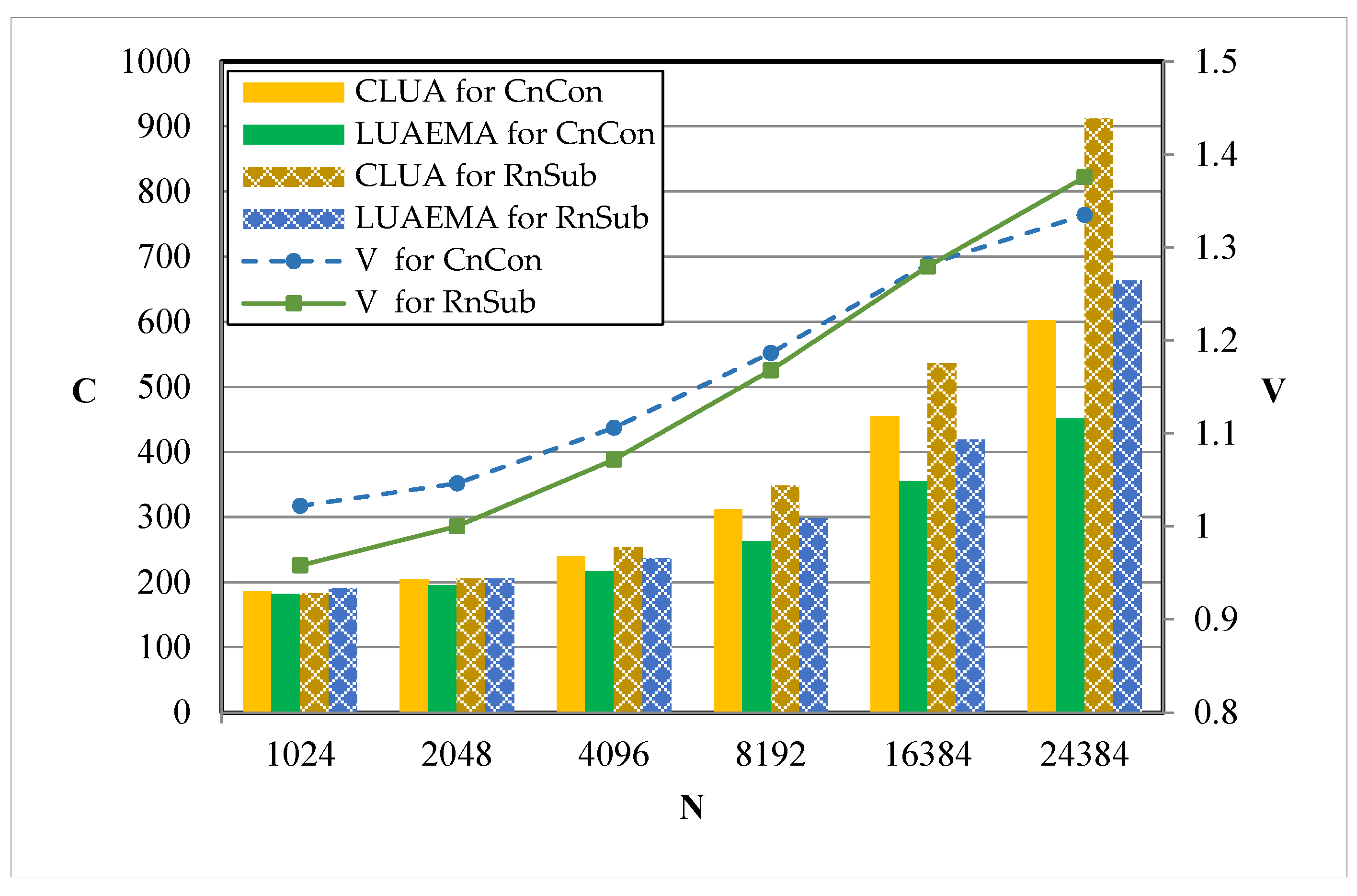
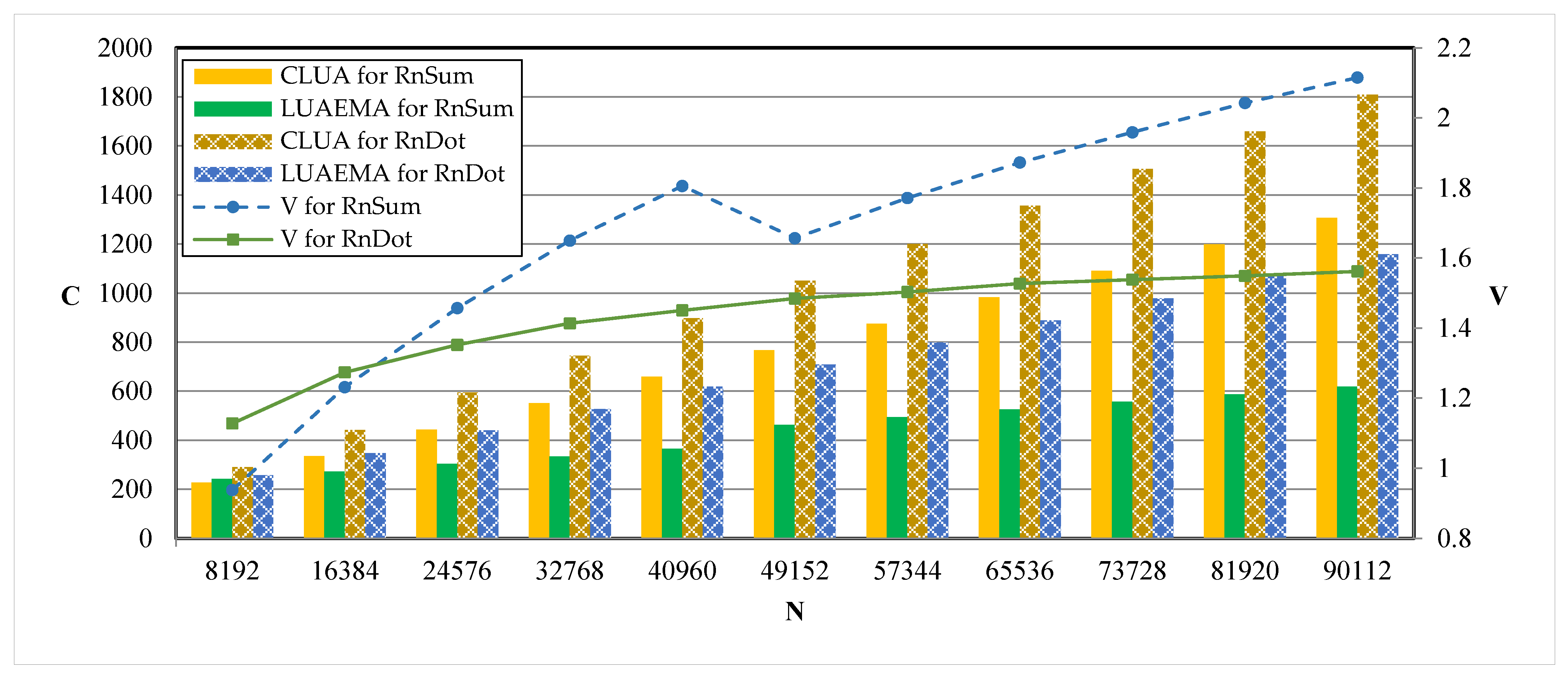
The input vector intermediate code of the algorithm is the same for both the conventional loop unrolling approach and the LUAEMA. For each algorithm, we consider several data volumes and obtain corresponding timing cycles by experiment. We use C, N, and V to represent the timing cycle, data volume, and speedup ratio, respectively. The results are shown in
Figure 6 and
Figure 7, where CLUA means that the corresponding values are obtained under the conventional loop unrolling approach, CnCon refers to the complex data conjugation algorithm, RnSub refers to the real data subtraction algorithm, RnSum refers to the real data summation algorithm, and RnDot refers to the real data dot product algorithm.
Figure 6 shows that for CnCon, when compared with the conventional loop unrolling approach, the speedup gradually increases with the increase in data volume, and the average speedup ratio is 1.16. When the data volume is 1024 or 2048, the timing cycles of RnSub under the LUAEMA are greater than those under the conventional loop unrolling approach. This is because the loop times are very small under our approach for small data volumes, and thus the profit of the decrease in loop times is smaller than the time cost of the auxiliary instructions introduced in this approach. As the data volume increases, the advantage of the LUAEMA becomes obvious. Compared with the conventional loop unrolling approach, the maximum speedup ratio of the LUAEMA is 1.38, and the average speedup ratio is 1.14.
Figure 7 shows that for RnSum, when the data volume is larger, the loop unrolling approach in this paper can obtain higher speedup than the conventional loop unrolling. And when the data volume reaches 90,112, the speedup ratio can be 2.11, and the average speedup ratio is 1.81; for RnDot, the increase in V gradually slows down as the data volume increases. When the data volume is around 90,112, V becomes a fixed value, and the speedup ratio is about 1.60.
The overall comparisons show that the LUAEMA can obtain an average speedup ratio of 1.36 over the conventional loop unrolling approach with the same algorithm.
6.2. Analysis of Unrolling Factors for Algorithms
In addition to analyzing the speedup ratios of the different algorithms, the internal unrolling of the algorithms provides a more intuitive demonstration of how the LUAEMA improves the code performance compared to the conventional loop unrolling approach.
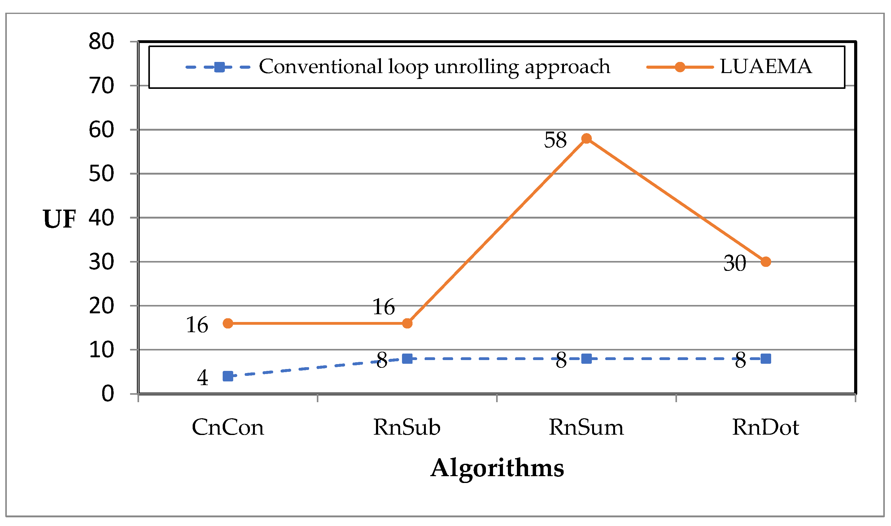
We use UF to represent the unrolling factor.
Figure 8 shows that the unrolling factor under the conventional loop unrolling approach for CnCon is 4, while the LUAEMA unrolls Rx and Ry to obtain the unrolling factor with a value of 16, which is a triple increase over the value of the unrolling factor compared to the conventional loop unrolling approach; the unrolling factor for RnSub under the LUAEMA is four times higher than that under the conventional loop unrolling approach; the unrolling factor for RnSum under the LUAEMA is increased by a factor of 6.25; and the unrolling factor of RnDot under the LUAEMA is increased by a factor of 2.75.
The original loop of CnCon uses two Rx, which are used to determine the base addresses of the real and imaginary parts of the complex array, and two Ry, which are used to read or write the different elements of the complex array in order. Whether the array is accessed sequentially by incrementing Rx or incrementing Ry, the unrolling factor under the conventional loop unrolling approach is 4. However, the LUAEMA can obtain an unrolling factor of 16 (4 × 4).
RnSub uses three address registers in the original loop to hold the base addresses of the minuend, subtracted, and resultant arrays and one offset register to read or write the elements of the three arrays sequentially. The unrolling factor under the conventional loop unrolling approach is 8, whereas the LUAEMA can obtain an unrolling factor with a value of 16.
The original loop of RnSum uses one address register to read the base address of the array. And the number of offset registers used is one. The unrolling factor under the conventional loop unrolling approach for RnSum is 8. The LUAEMA, on the other hand, can obtain an unrolling factor of 64 while ensuring that the other register resources are sufficient (in practice, it can only unroll 58 times because the number of other register resources available is not sufficient to unroll 64 times).
When the input code is RnDot, the unrolling factor under the conventional loop unrolling approach is 8. However, the LUAEMA considers the full utilization of memory access registers and obtained an unrolling factor of 30. Before register spilling happens, the unrolling factor by Rx is 4 and that by Ry is 8. Fully utilizing Rx and Ry in the LUAEMA can increase the unrolling factor to 32, but the unrolling factor for the general register is 30. Therefore, the final unrolling factor is 30.
Combining the speedup ratios of the timing cycles derived from the comparisons and the increase in the unrolling factors of the different algorithms, it can be found that when the unrolling factor is larger, the advantage in timing cycles is greater. The conventional loop unrolling approach cannot take full advantage of the multi-register types of vector DSP, while the LUAEMA can achieve better performance before register spilling happens.
7. Conclusions and the Future Work
In this paper, we propose an instruction-level loop unrolling approach for a vector DSP that makes full use of different register types, the LUAEMA, in response to the limitation that the conventional loop unrolling approach leads to unused free registers in vector DSPs. Firstly, the authors analyze the limitations of the conventional loop unrolling approach implemented on a vector DSP, which in turn leads to its insufficient use of registers. Secondly, a mathematical model is constructed to elucidate the basic principles of the LUAEMA. Then, the implementation process of the LUAEMA is explained by introducing several algorithms for loop unrolling. In order to verify the effectiveness of this approach, the authors selected four algorithms on the FT-M7002 DSP. The experiments show that the LUAEMA’s code optimization on the FT-M7002 DSP significantly outperforms the conventional loop unrolling approach, where the unrolling factor is increased by 3.25 on average, and the speedup ratio is up to 1.36 on average. The LUAEMA is a loop unrolling approach in compilation optimization, which is an automatic processing pass for its input code, and thus the output unrolled loop code is automatically generated. However, because its input is instruction-level intermediate code, we need to manually write the instruction-level intermediate code corresponding to the high-level language. The same applies to the conventional approach.
A vector DSP not only uses the address register and offset register to access memory but also uses the address register and immediate number to access memory. This indicates that the immediate value can be used in the instruction instead of the offset register, and the usable number of the offset register can be the sum of the actual total number and the number of immediate values. Therefore, our next work is to consider the memory access mode of the address register and immediate number to improve the LUAEMA. Besides, the unrolling factor is not restricted by the requirement of avoiding the generation of register spilling code. Therefore, we can try to study the method to further expand the unrolling factor, so that the corresponding code can run more effectively on vector DSPs.


