Article

DCGFuzz: An Embedded Firmware Security Analysis Method with Dynamically Co-Directional Guidance Fuzzing

1
School of Computer Engineering and Science, Shanghai University, Shanghai 200444, China
2
Purple Mountain Laboratories, Nanjing 211111, China
*
Author to whom correspondence should be addressed.
Electronics 2024, 13(8), 1433; https://doi.org/10.3390/electronics13081433
Submission received: 4 March 2024 / Revised: 31 March 2024 / Accepted: 8 April 2024 / Published: 10 April 2024
(This article belongs to the Special Issue Cybersecurity Issues in the Internet of Things)

Abstract

:
Microcontroller Units (MCUs) play a vital role in embedded devices due to their energy efficiency and scalability. The firmware in MCUs contains vulnerabilities that can lead to digital and physical harm. However, testing MCU firmware faces challenges due to various tool limitations and unavailable firmware details. To address this problem, research is turning to fuzzing and rehosting. Due to the inherent imbalance in computational resources of the fuzzing algorithm and the lack of consideration for the computational resource requirements of rehosting methods, some hardware behavior-related paths are difficult to discover. In this work, we propose a novel Dynamically Co-directional Guidance Fuzzing (DCGFuzz) method to improve security analysis efficiency. Our method dynamically correlates computational resource allocation in both fuzzing and rehosting, computing a unified power schedule score. Using the power schedule score, we adjust test frequencies for various paths, boosting testing efficiency and aiding in the detection of hardware-related paths. We evaluated our approach on nine real-world pieces of firmware. Compared to the previous approach, we achieved a maximum increase of 47.9% in path coverage and an enhancement of 27.6% in effective model coverage during the fuzzing process within 24 h.

1. Introduction

In recent years, the field of Internet of Things (IoT) has seen rapid development, with many technologies related to IoT and embedded devices, such as blockchain [1,2] and edge computing [3], becoming research hotspots. Microcontroller Units (MCUs), as crucial components of modern embedded devices, have been widely used in various scenarios, including healthcare, autonomous driving vehicles, and industrial systems. At the same time, the security of MCUs has also attracted widespread attention from researchers [4].
MCU firmware contains vulnerabilities that may cause various attacks that result in damages in both digital and physical words. For example, attackers can use the notorious Mirai botnet [5] to hijack many IoT devices and launch Distributed Denial of Service (DDOS) attacks, resulting in the disruption of thousands of websites. Additionally, attacks targeting the system level can pose even greater threats. For instance, after an attack on Programmable Logic Controllers (PLCs), hackers could manipulate vulnerable components such as the centrifuge rotor [6], speeding up or slowing down its operation, therefore causing damage to the entire industrial equipment and even posing a threat to human safety.
However, due to limitations in the performance of tools, hardware constraints, and the need for prior knowledge, a significant number of MCU firmware lack comprehensive testing [7]. First, the effectiveness of tools like Snipuzz [8] is constrained by the limitations of peripherals and I/O performance. Second, the operation of IOTFuzzer [9] relies on information carried by the application. Finally, due to MCU firmware typically being in binary format and lacking public disclosure, the investigation of MCU firmware bears a closer resemblance to a black-box problem for researchers.
To deal with the above limitations, fuzzing and rehosting emerge as significant directions for research. Rehosting is a firmware emulation technique that simulates real hardware devices in a virtual environment. The design approach of rehosting methods involves abstracting hardware devices into models through various means and maximizing the coverage of these abstract models to simulate hardware devices more comprehensively. Fuzzing is a security analysis method that triggers vulnerabilities in programs by generating various types of inputs. One prevalent type of research, based on path coverage [10,11,12,13], focuses on improving path-coverage algorithms to thoroughly test program branches [14]. Therefore, after successfully simulating the device to be analyzed, rehosting methods typically integrate fuzzing techniques for firmware security analysis [15,16,17]. These methods generally directly utilize existing fuzzing frameworks [18,19].
Currently, these rehosting frameworks combined with fuzzing frameworks have various limitations. On the one hand, commonly used frameworks such as QEMU [20] and Unicorn [21] cannot be directly utilized without prior knowledge of the relevant embedded devices, nor can they adequately adapt to the demands of fuzzing. On the other hand, frameworks like Pretender [22] feature complex designs, demanding environmental requirements, and numerous dependencies where minor version changes could impede their functionality. This implies that these methods are difficult to integrate with other frameworks.
In recent years, other advanced methods primarily focus on optimizing framework designs and simulating more peripherals to enhance performance [15,16,23,24,25,26,27]. This makes it difficult to improve the performance of these rehosting methods. New outstanding research often involves re-proposing a framework. This entails a significant amount of engineering effort, and further work is also challenging.
However, when applying these excellent studies directly to firmware related to industrial equipment, these methods may not be as effective as expected [28]. On the one hand, fuzzing testing algorithms themselves also have limitations, such as the problem of unbalanced computing resources [29]. After a period of testing, some paths may be tested too frequently while others lack testing. On the other hand, we found that certain firmware program branches need to trigger specific hardware functions to reach, and when allocating computing resources, fuzzing testing algorithms did not consider the need for rehosting methods. This makes it difficult to discover paths related to peripheral device functions. We refer to these paths as hardware behavior-related paths (or code branches).
Therefore, we are considering improving the efficiency of rehosting methods from the perspective of computational resource allocation. This includes enhancing the efficiency of path discovery by the fuzzing algorithm and improving the capability of rehosting methods to discover peripheral device behaviors, therefore aiding in the detection of hardware behavior-related paths. To assess the efficiency of both processes, we employ path coverage and model coverage as metrics [14,30]. Here, model coverage is represented by the number of paths discovered during fuzzing, while model coverage is similarly represented by the number of models successfully simulated during the fuzzing process. In the implementation process, we need to address the following challenges:
  • How to establish a suitable firmware emulation environment. The problem includes the resolution of all peripheral devices and resetting their state to the required configuration for fuzzing. Additionally, a robust operating environment is necessary for successful fuzzing, and automation should be implemented throughout the execution process. This paper mainly considers rehosting methods, so the problem transforms into selecting the type of rehosting method and framework compatible with the overall algorithmic structure while maintaining high performance.
  • How to allocate computing resources, i.e., what fuzzing methods to adopt. In software fuzzing, there are many different types of methods, such as bitmap-based [31], protocol state machine-based [32], DSE (Directed Symbolic Execution) [33], taint analysis, etc. However, many of these approaches are not particularly effective when applied to firmware. For example, Dynamic Symbolic Execution (DSE) is not directly suitable for firmware fuzzing [14], as DSE requires support from the running environment, necessitating extensive modifications to the firmware emulation framework.
  • How to integrate fuzzing and rehosting processes effectively. We need to establish a unified statistical mechanism for allocating computational resources. This mechanism should aim to fulfill the requirements of fuzzing to discover as many paths as possible while also addressing the need for rehosting to uncover as many models as feasible. Furthermore, we must reduce computational resource wastage because firmware emulation is generally less efficient compared to desktop platforms like Windows, and the process of hardware abstraction modeling consumes significant resources. In this process, we need to design appropriate metrics and associated algorithms.
To deal with the above challenges, we propose a novel MCU firmware security analysis method named Dynamically Co-directional Guidance Fuzzing (DCGFuzz). The key technique used in our method is called Dynamically Co-directional Guidance (DCG). Its core is the new seed schedule, which involves both fuzzing and rehosting. DCG integrates the characteristics of firmware, improves the overall computational resource allocation strategy, considers the task requirements of rehosting, and effectively improves the overall efficiency of the framework. Here, a seed refers to the input text used for fuzzing, and a seed schedule is a method of resource allocation that influences the input text, which includes power scheduling and seed selection. These aspects will be detailed in Section 2.1.1. Specifically, the contribution of this work is as follows:
  • We introduced new parameters and designed a new power schedule algorithm to dynamically and uniformly allocate computational resources for both fuzzing and rehosting. We calculate a score for each seed, taking into account both the performance of fuzzing and rehosting. Through this score, we determine the allocation of computational resources so that both fuzzing and rehosting can influence the direction of resource allocation. Additionally, we designed corresponding seed selection strategies to determine the priority of seeds.
  • We designed a segmented seed scheduling strategy based on firmware characteristics to improve the allocation of computational resources. The seed scheduling strategy effectively tests high-value paths while preventing excessive testing of certain paths.
  • We made significant algorithmic adjustments to the fuzzing framework and performed extensive compatibility work between the fuzzing and rehosting frameworks. Ultimately, we ensured that the overall framework ran smoothly and effectively.
  • We validated our proposed method through experiments. Based on the experimental results, we discussed the effectiveness of our approach and proposed directions for future work.
The rest of this work is structured as follows: Section 2 explains some basic concepts and summarizes the current state of related research. Section 3 presents the overall framework of our method, including its design principles, and provides a detailed description of the specific algorithms. Section 4 presents our experimental design and results. Section 5 discusses the experimental findings and introduces some ideas for future work. Section 6 is the conclusion of this paper.

2. Background

MCU firmware is typically a monolithic piece of software, encompassing peripheral device drivers, a small operating system or system libraries, and a set of specialized logic or applications. Due to hardware constraints and specific product requirements, MCU vendors extensively utilize custom operating systems to build MCU firmware, such as systems customized based on Real-Time Operating Systems (RTOs) like VxWorks [34] and QNX [35]. However, these custom operating systems often lack sufficient effective documentation for various reasons, necessitating that testers rely heavily on expert experience when testing such firmware.
In response to the current state of firmware security issues, researchers in recent years have attempted a variety of methods, including runtime attack mitigation [36], remote authentication [37,38], firmware analysis [39,40], and concolic execution [41]. These methods typically have significant limitations, such as the need for hardware modifications, and some have a high rate of false positives. One of the more effective approaches is dynamic analysis within firmware analysis [42]. Fuzzing is an effective dynamic analysis method. In the field of software security analysis, coverage-guided fuzzers have shown exceptional performance in gray-box and black-box testing. AFL [18] and its more advanced extensions [43,44] are a good example. They have detected many serious vulnerabilities in desktop-level applications and operating systems. The following text will refer to these fuzzing methods for applications and operating systems as application software fuzzing methods.
However, due to the lack of information about peripherals, fuzzers other than black-box fuzzers are challenging to apply to embedded devices. Therefore, researchers utilize rehosting frameworks to run firmware in a virtual environment and then conduct gray-box fuzzing using existing fuzzing testing tools. This also brings about the research problem addressed in this paper, which will be elaborated on in Section 3.1.

2.1. Fuzzing

Fuzzing is one of the most successful techniques to detect security flaws in programs [45]. Fuzzing is the process of searching for a finite set of inputs within an infinite input space to trigger vulnerabilities. During fuzzing, all selected inputs are executed within the programs under test (PUT), and the program’s behavior is examined to confirm whether a crash has been triggered. Firmware fuzzing can be considered a branch of fuzzing. This paper refers to the fuzzer as the program that implements the fuzzing algorithm.
Typically, coverage-guided fuzzers are referred to as CGFs (coverage-based gray-box fuzzers) [43]. CGFs (Coverage-Guided Fuzzers) have several advantages in many aspects. For example, Polyfuzz [46] can be used across multiple platforms. Rainfuzz [47] can also be combined with reinforcement learning to improve efficiency.
Due to the excellent performance, portability, and scalability of CGFs, we have also chosen the coverage-guided fuzzing method AFL (American Fuzzy Lop) for resource allocation. Below, we will introduce the resource allocation strategy used by CFGs, known as seed scheduling, and provide an overview of AFL, the fuzzing testing framework used in this paper.

2.1.1. Seed Schedule

For coverage-guided fuzzing methods, researchers primarily focus on seed [48]. A seed is a text randomly generated or crafted by a researcher. The fuzzing program uses this text to generate multiple inputs, which are then used to test the PUT. A seed represents an executable path, and researchers express the algorithm’s interest in different paths by assigning weights to seeds.
The performance of such fuzzers largely depends on seed scheduling, which includes seed selection and power schedule [49]. Seed selection determines the priority of seed fuzzing [50], indicating which paths are prioritized for testing. The power schedule determines the frequency of seed fuzzing [10] in each testing round and how many inputs are generated from each seed for testing. This also represents the weights of paths corresponding to the seeds.
By adjusting seed scheduling, researchers can modify the allocation of computational resources for different tasks [51], allowing the fuzzing algorithm to adapt to various scenarios.

2.1.2. AFL

AFL [18] is a widely used coverage-guided fuzzing framework. The official version provides numerous interfaces for researchers to customize their requirements. When AFL combines with rehosting frameworks (such as QEMU [20]) for firmware fuzzing, it first generates a seed corpus, followed by arbitrary rounds of fuzzing. The general process for each round of testing is as follows: Through seed selection, a seed is chosen from the seed corpus. Then, using the power schedule, the number of inputs generated by this seed is calculated. All inputs are saved as files and transmitted to the rehosting framework via API. The rehosting framework executes the inputs and returns the corresponding bit map via shared memory, which records the path coverage during the execution of the inputs in the rehosting framework. By inspecting the bit map, it is determined whether new paths have been discovered in the rehosting framework. If so, the input is added to the seed corpus. The next round of fuzzing is then conducted. The following are AFL’s power schedule and seed selection strategies.
Power schedule: AFL calculates a power score and then divides the power score by a constant to determine the number of inputs generated for the current seed. The power score P A ( i ) of AFL is correlated with the average execution time t m ( i ) , block transition coverage b ( i ) , and seed depth d ( i ) of seed i. t m ( i ) represents the average execution time of all inputs generated by seed i in the current round. b ( i ) is derived from the bitmap and is positively correlated with the number of paths covered by seed i. d ( i ) represents the maximum path depth explored by seed i, reflecting its ability to explore path branches. For example, if i 0 is ‘0’ and discovers path A and i 1 is ‘01’ and discovers code branch B based on path A, then d ( i 0 ) = 1 and d ( i 1 ) = 2 . The expression for P A ( i ) is as follows:
P A ( i ) = S ( t m ( i ) ) · f 1 ( b ( i ) ) · f 2 ( d ( i ) )
where S ( ) outputs an initial score S 0 , which is negatively correlated with the input. f 1 ( ) and f 2 ( ) output two factors f 1 and f 2 , which are positively correlated with the input.
Seed selection: AFL’s seed selection is divided into two parts: favorite queue and seed splicing.
Before selecting a seed, AFL maintains a favorite queue for all explored code branches, where each branch represents an element in the queue. This element stores an optimal seed and is iteratively updated during testing. AFL compares the priority of seeds by calculating a f a v _ f a c t o r ( i ) . The expression for f a v _ f a c t o r ( i ) is as follows:
f a v _ f a c t o r ( i ) = t m ( i ) · l e n ( i ) ;
f a v _ f a c t o r ( i ) is calculated based on t m ( i ) , which is the same as in the power schedule, and l e n ( i ) , representing the length of seed i. In simple terms, AFL prioritizes shorter seeds and executes faster. When the fuzzer randomly selects seeds for testing, it prioritizes favorite seeds for fuzzing. This is achieved by the fuzzer probabilistically skipping each seed; seeds with higher priority have an extremely low probability of being skipped.
After selecting a seed i in AFL, a certain number of seed splicing processes are carried out. Seed splicing refers to the process where the fuzzer randomly replaces a portion of text from seed i with a portion from another seed. We refer to the text of seed i as b u f i . During the splicing process, the fuzzer randomly selects another seed j, takes a text fragment b u f i 0 from b u f i and a text fragment b u f j 0 from b u f j , and splices b u f i 0 and b u f j 0 to form b u f i j . This is then re-mutated to form a new set of inputs. AFL employs this method to increase the diversity of mutations applied to seed i.

2.2. Rehosting

Firmware emulation is used to run and analyze the firmware of embedded devices in a virtual environment without the need for actual hardware devices. Due to non-standardized development processes and differences between emulation and physical environments, firmware emulation is challenging. If libraries, device drivers, device kernels, and peripherals cannot be accurately emulated, it is not possible to execute the firmware [15].
Unlike hardware emulation systems, which fully replicate hardware functions in a virtual environment, a rehosted embedded system only reproduces the hardware functions necessary to enable the firmware (or relevant components thereof) to operate in a virtual environment [52] fully. This process may involve modifications to the firmware. In addition, rehosting is an iterative process where the implementation of hardware functionality is replicated incrementally across iterations.

2.2.1. Category

Currently, rehosting methods mainly fall into the following two categories:
Hardware-in-the-loop: Due to the complexity of peripheral devices, some studies have chosen to circumvent the abstract modeling of peripherals. Instead, they use a partial emulation approach, redirecting content related to peripherals to actual devices during the fuzzing process [53,54,55]. This approach can partially bypass the black-box problem and simplify the dynamic analysis of firmware. However, it is important to note that hardware-in-the-loop also has drawbacks. Bandwidth limitations restrict fuzzing speed, and state resetting remains challenging for actual hardware.
Pure Rehosting: Using full emulation can free the firmware security analysis process from most hardware limitations. Some approaches have limitations on the system or the MCU [15,16,23,24,25,26,27,56], but within the limited operational scope, these approaches perform well. The primary objective of such approaches is to create abstract models. Some approaches use heuristics to model the physical devices involved in the firmware [24,25,26,27], while others directly utilize existing abstract models of operating systems [15,16,23,56]. Unfortunately, the performance and efficiency of these methods are limited by the requirement for specific target prior knowledge and some manual operations. Fuzzing requires a high degree of automation and an environment that supports parallel execution. Manual operations and environmental limitations result in additional efficiency losses for security analysts when using these methods in practice [28]. Other approaches have developed more complex frameworks to reduce manual intervention, such as uEMU [57], Fuzzware [17], and DevFuzz [58]. While these methods are generally excellent, for our research, the environmental requirements of these frameworks are higher, and the workload for modification and adaptation is greater.
In our research, we require a rehosting method to serve as an emulator. The emulator is responsible for executing binary firmware and establishing virtual models for all peripheral functionalities involved in the firmware. Therefore, we hope the emulator will be: (1) lightweight and scalable; (2) stable; and (3) automated. These features would enhance compatibility with fuzzing testing algorithms, facilitating the debugging and research of our algorithms. A category of research known as pattern-based MMIO modeling provides an excellent solution [22,30,59]. Therefore, we have chosen P2IM [30] from this category as the emulator for our framework.

2.2.2. P2IM

P2IM [30] framework is based on a characteristic of peripherals: their types and protocols are diverse, making it difficult to create abstract models directly, but the interfaces for firmware interaction with peripherals are relatively fixed. Firmware interacts with peripherals via three interfaces: DMA (Direct Memory Access), MMIO (Memory Mapped I/O), and interrupts. Typically, firmware and peripherals exchange a small amount of data and interact primarily through MMIO and interrupts. By creating abstract models of MMIO and interrupt behavior, it is possible to emulate the behavior of peripheral devices.
Below is a detailed introduction to the P2IM framework. For P2IM, the process of peripheral abstraction modeling mainly consists of abstract model definition, model instantiation, and specific model execution.
Abstract Model Definition: This process defines a set of abstract memory models based on expert experience. These memory models enable the emulator to handle firmware memory access behavior accurately. The definition of the memory models includes the following components:
(1)
Access Patterns: The emulator classifies the firmware’s access to memory into accesses to different registers based on the behavior patterns of the registers during operation.
(2)
Handling Strategies: The emulator sets different response methods according to the types of registers classified by the access patterns.
(3)
Interrupt Firing: The emulator stores interrupts as time-series-based inputs and triggers them at specified intervals.
Model Instantiation: During this process, the emulator categorizes and processes each instruction in the firmware emulation. Instructions not related to peripherals are emulated directly by QEMU. If an instruction is peripheral-related, its address falls within the MMIO address space, which is a reserved memory read/write area for firmware/peripheral interaction. Based on the definitions of the abstract models, the emulator classifies the instruction’s address as different registers and records the corresponding response methods. Each instruction represents a firmware behavior towards a peripheral, and the recorded response is the emulator’s simulated peripheral’s response to the firmware behavior. This information forms an instantiated model. All instantiated models are stored as files in a model pool.
Model Execution: During this process, the emulator attempts to execute the firmware using external input files provided by the fuzzer. If the emulator detects that an instruction accesses the MMIO address space or triggers an interruption, it calls the corresponding instantiated model to generate the appropriate response. The emulator then feeds these responses back to the firmware. If the execution proceeds without errors, the emulator successfully simulates an interaction between the firmware and a peripheral. If a suitable peripheral model is not found in the model pool, the emulator runs a model re-instantiation process, which continues until a successful model is built or the number of re-instantiations exceeds a predefined limit. Model re-instantiation refers to re-executing the model instantiation for currently unknown instructions.
Overall, the flow of running the P2IM framework is as follows: Initialize the running firmware with a random input. A Model Instantiation step is performed for common hardware behaviors based on the abstract model definition. After that, it accepts the input generated by the fuzzer and runs the firmware. If hardware-related instructions are encountered, the model execution step (including the re-instantiation process) is performed. Until the fuzzer no longer generates input.
In addition, our work validates the method using the open-source firmware dataset presented in P2IM [30].

2.3. Coverage

Coverage refers to the extent to which the source code is covered, and research has shown that greater code coverage increases the probability of defect detection [60]. When conducting firmware security analysis, researchers lack access to the source code, necessitating a change in how coverage is represented. Given that the total number of codes in firmware is fixed, measuring code coverage for CGFs is relatively straightforward: the number of paths reached by seed exploration represents the degree of code coverage. For emulators, model coverage serves a similar concept. In P2IM, the number of successfully emulated models represents the degree of firmware emulation, where each model represents a peripheral device’s functional behavior. For firmware fuzzing, these functional behaviors hold greater testing value [30], and larger model coverage signifies more comprehensive testing. If higher coverage rates are achieved within a unit of time, indicating that more areas have been explored within that time frame, we consider the method to be more efficient.

3. Methodology

3.1. Problem Definition

The paper addresses two problems that require improvement:
Problem 1 (P1): For basic coverage-based gray-box fuzzers (CGFs), there is a notable feature in path exploration: since each seed involved in fuzzing does not carry information from its predecessors, later generated seeds continue to test paths already tested by previous seeds, leading to an uneven distribution of computational resources.
Taking AFL as an example, as shown in Figure 1, let us assume that our first seed S 1 is ‘110’, which triggers the path in line 2 of the figure. We assume that each mutation process is as follows: (1) randomly select a position in S 1 , (2) replace the original digit at the selected position with a random number between 0–9. Under these conditions, the probability of the fuzzer moving from line 2 to line 3 is 1 27 = 1 3 · 1 9 . Assume that when the mutation of S 1 generates 27 inputs, the fuzzer manages to detect line 3. At this point, the fuzzer saves seed S 2 as ‘100’. Among the other 26 inputs, 17 cover the ineffective path ‘1X*’ (where X represents the number corresponding to the invalid path, here 1–9, and * represents any digit, indicating no effect on the execution path), and 9 covers the ineffective path ‘X**’. In the second round of testing, with two seeds, ‘110’ and ‘100’, the fuzzer mutates them to generate 27 inputs each. Out of 54 inputs, we found 26 inputs (17 from S 1 , 9 from S 2 ) testing path ‘1X*’, which is unnecessary. Only the 9 inputs from S 2 are testing the path ‘10*’ (attempting to transition from line 3 to line 4), which could cause a crash. In other words, under the current assumption, the mutation of seed S 1 in the second round of fuzzing is worthless.
The situation arises because the fuzzer fails to record information about previous seeds. Over time, newly generated seeds will also test paths that were tested by previous seeds. We refer to paths tested more than the median number of times as high-frequency paths, such as the ‘1X*’ path in the example above. Similar to application software fuzzing, firmware fuzzing with AFL gradually tends to mutate the test cases to repeatedly test high-frequency paths. With AFL and similar fuzzers, this is inevitable. After several rounds of iteration, for a new seed S 2 , the previous state (‘1X*’) is forgotten, and the previous paths have the same probability of being generated as new paths (‘10*’). This leads to a higher total number of tests for the previous paths. In the example above, this can be seen by the fact that ‘1X*’ is tested several times. We define the seeds corresponding to these high-frequency paths as over seeds. For example, in the case above, the seed corresponding to the path ‘1X*’ (i.e., one of [‘11*’, ‘12*’, ‘13*’, …, ‘19*’], as the fuzzer only stores one seed per path). In contrast, seeds corresponding to less frequently tested paths are defined as under seeds, such as ‘10*’. We define the average number of executions required to discover each path as the average cost. After a certain number of fuzzing rounds, the fuzzer repeatedly tests high-frequency paths, making it difficult to discover new paths. The inputs generated by the over seeds corresponding to these paths have a higher average cost to the fuzzer and yield a lower average benefit. Therefore, for the fuzzer, prioritizing under seeds corresponding to less frequently tested paths can effectively test these low-frequency paths, reducing computational waste and increasing efficiency.
Problem 2 (P2): As described in Section 2.1.2, during firmware fuzzing, the fuzzing algorithm generates inputs through seed scheduling, which are then iterated through the rehosting framework to generate peripheral models. It is important to note that the process of rehosting model generation occurs within the fuzzing process. Here, we refer to the requirement of increasing coverage in fuzzing as the path-coverage task and the requirement of enhancing peripheral emulation in rehosting as the model-coverage task. Thus, for a seed i, both paths and models must be discovered. CGFs such as AFL allocate computational resources for i based solely on path-related parameters ( b ( i ) and d ( i ) , refer to Section 2.1.2). This would not be an issue originally, but for some firmware with numerous hardware-related behaviors, many paths are closely related to hardware behaviors, making it difficult to discover some crucial paths. As mentioned in Section 1, we refer to these paths as hardware behavior-related paths. Let us illustrate this with an example.
As shown in Figure 2, functions starting with “handle” represent those related to peripherals. For example, when testing the program depicted in the diagram, we have input seeds i B : ( o p = B , f l a g = T r u e ) and i C : ( o p = C , f l a g = T r u e ) . Here, i B can reach lines 4 and 5, and after several mutations, it can easily discover the path to line 6. However, i C can reach line 8, but due to hardware-related opcodes, it is difficult to reach line 10. According to AFL’s method of calculating power score (detailed in Section 2.1.2, power schedule), i B has a larger b ( i ) because it currently reaches more code branches, thus resulting in a higher power score and being allocated more computational resources. Conversely, i C spends more time executing h a n d l e _ B _ S t a r t ( ) , and although it reaches fewer code branches, only line 8, its t m ( i ) is larger and b ( i ) is smaller, resulting in a smaller power score. Consequently, i C receives fewer computational resources, and the specific value “SPECIAL” needed in h a n d l e _ B _ S t a r t ( ) to trigger specific functionality leads to a vicious cycle, making it harder for the testing process to discover the path from line 10 to line 12. These paths require testing similar seeds to i C , while the fuzzing algorithm focuses more on seeds like i B , even though the repeated testing of i B is redundant and not very important. This issue has minimal impact on firmware with fewer peripheral device behaviors. However, for firmware with many peripheral device behaviors, many critical program branches require specific hardware behaviors to be triggered. In summary, solely focusing on the allocation of computational resources based on path coverage can overlook many important hardware behavior-related paths.

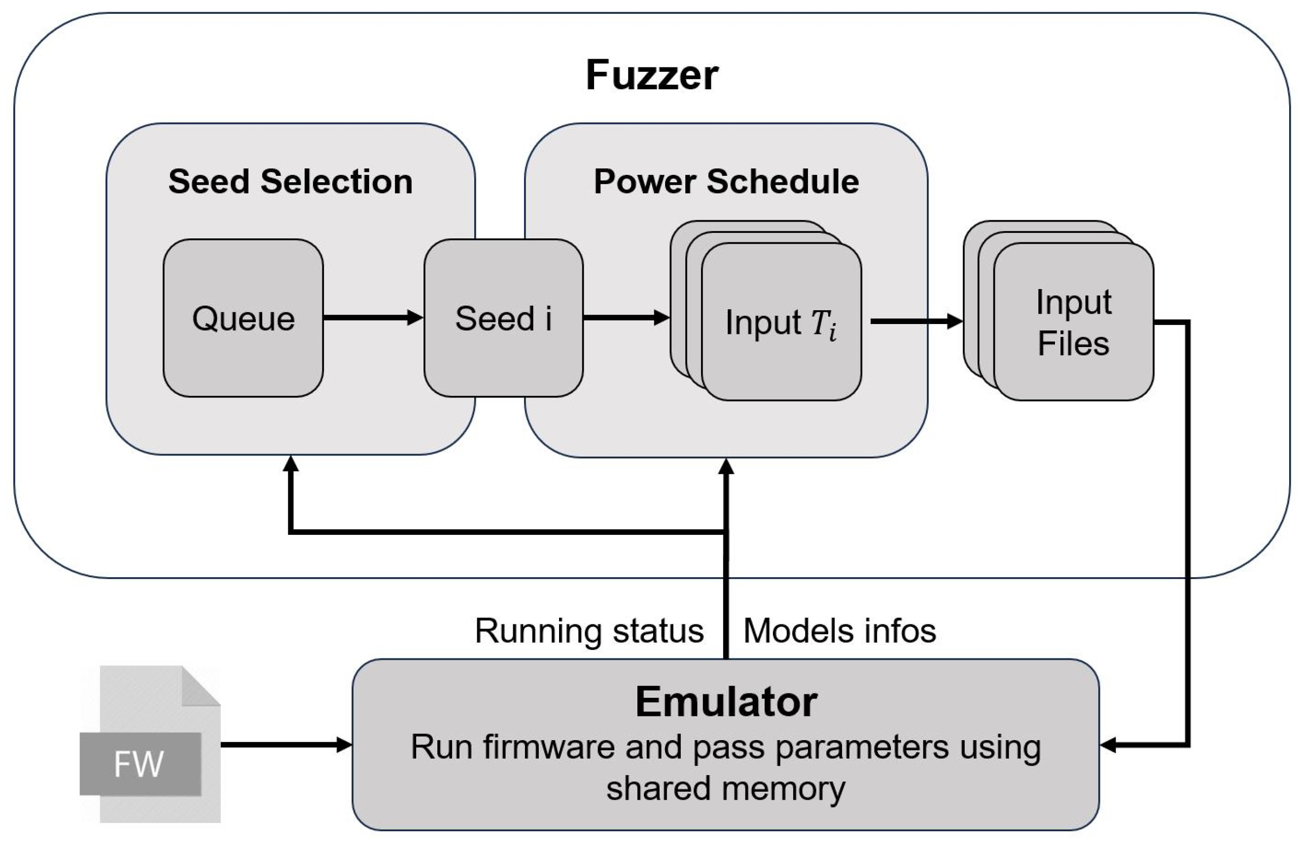
3.2. Framework Overview

Based on the above-mentioned issue, we designed the DCGFuzz algorithm framework, primarily focusing on a new seed schedule and adjusting the computational resource allocation scheme. By employing this approach, we can simultaneously focus on both seed path coverage and model coverage, dynamically allocate computing resources in a unified manner, meet the needs of both the fuzzer and emulator, and enhance overall efficiency.
The framework of our method, as shown in Figure 3, consists primarily of the fuzzer and the emulator. The fuzzer is based on AFL, while the emulator is based on P2IM.
When fuzzing firmware, the emulator attempts to establish a simulated runtime environment. Once the runtime environment is successfully established, the emulator notifies the fuzzer to begin fuzzing. In each round of the fuzzing process, the fuzzer reads an initial seed file to serve as the seed corpus. Using the seed selection strategy, the fuzzer selects an interesting seed i from the queue. The fuzzer extracts text from seed i for mutation and uses the power schedule to determine the number of inputs generated from mutation, resulting in the input set T i . The size of T i represents the amount of computing resources allocated to seed i. For each input t T i , the fuzzer generates a corresponding input file as an input for the emulator. The emulator inputs the file into the firmware and returns the execution results and relevant parameters to the fuzzer. The fuzzer records this information, and a portion of it serves as a parameter for the seed schedule. These parameters are involved in the calculation of the power schedule during subsequent fuzzing and influence the seed selection process.
In summary, by controlling the size of T i generated by seed i and the priority of seed selection, we can reallocate computing resources in firmware fuzzing. We will detail the power schedule algorithm in Section 3.5 and the seed selection algorithm in Section 3.6.

3.3. Method Design Principles

This section elucidates the design philosophy behind the overall DCGFuzz algorithm.
The DCGFuzz design is based on a fundamental principle: to improve the efficiency of fuzzing, including path coverage and model coverage. Thus, we translate solutions to problems P1 and P2 into two specific tasks. P1 corresponds to the path-coverage task, which focuses on improving the allocation strategy of computational resources to enhance the efficiency of path-coverage. P2 corresponds to the model-coverage task, focusing on enhancing the efficiency of model coverage to swiftly identify hardware behavior-related paths.
Computational resources are not created out of thin air. Thus, the DCGFuzz method effectively divides into two components. The path-coverage task necessitates reallocating computational power from seeds with higher testing frequency to those with lower; for the model-coverage task, it entails transferring 1 k of computational resources from the path-coverage task to the model-coverage task. The extent of this transfer depends on the actual scenario of models within the task, with designs featuring more peripherals potentially justifying a larger resource transfer. The subsequent section elaborates on the design principles and relevant parameters for both tasks.

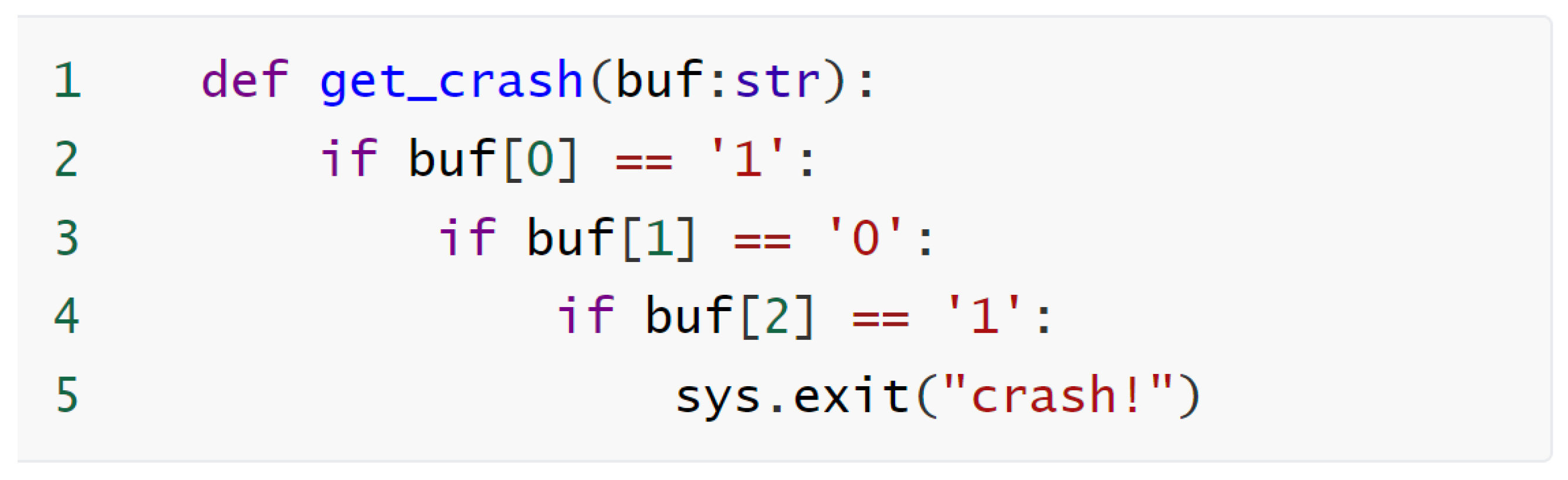
3.3.1. Path-Coverage Task

In P1, it has been highlighted that Conventional Genetic Fuzzers (CGFs) often suffer from the issue of over-allocating computational resources to certain paths. Therefore, an ideal improvement strategy to enhance efficiency and reduce overhead is to refrain from testing high-frequency paths and primarily focus on low-frequency paths [29]. For instance, calculating the average number of test executions for all paths and using it as a threshold beyond which paths are no longer tested may seem like a viable solution. However, this approach is not suitable for firmware fuzzing. In layman’s terms, low-frequency paths refer to those whose cumulative test case count is significantly lower than the mathematical expectation of path discoveries, indicating a high probability of uncovering new paths. In firmware fuzzing, there are two key points to consider: (1) First, due to the time overhead of the rehosting framework, the average speed of firmware fuzzing is generally slower than that of software fuzzing. This implies that a longer testing duration is required to achieve the expected number of test cases for path discovery. (2) Firmware fuzzing tasks involve some special values, such as line 9 in Figure 2. To randomly mutate these values, a relatively large number of test cases is needed from a mathematical expectation perspective. Considering points (1) and (2), it becomes evident that solely focusing on low-frequency paths for testing is not appropriate. Conversely, even if certain paths exceed the mean number of test executions, we still believe they retain a certain testing value.
The strategy might seem contradictory at first glance, so we specifically adopted a segmented fuzzing approach.
Initially, we enter the rapid depth exploration phase. We refer to the average number of times all paths are tested as the average test frequency. At this stage, we only assess seed quality without concerning ourselves whether the seed’s testing frequency exceeds the average test frequency. We select seeds with less overlap between their paths through an algorithm, which are referred to as high-quality seeds. We use a subset of high-quality seeds as probe seeds and trust that they are low-frequency. These probe seeds are prioritized for deep testing to expedite their exploration of deeper code paths.
After a certain period, when the overall testing process hits a bottleneck (a short period without discovering new paths), we believe it is necessary to execute the phase-switching function to transition the algorithm into the flexible breadth testing phase. This is because the probe seeds have been thoroughly tested and are unable to uncover further paths, necessitating the reallocation of computational resources to other seeds. During this phase, the average testing frequency is computed and used as a threshold. This is the essence of elasticity, where reducing the testing frequency of high-frequency paths replaces the complete absence of testing for such paths. This can also be understood as the presence of certain special values in the firmware code that are required to trigger certain branches. Therefore, we trust that the testing frequency of some paths has not yet reached the expectation of discovering new paths. Seeds exceeding this threshold have their resource allocation reduced, while seeds below the threshold have their resource allocation increased. Finally, when the flexible breadth exploration phase also reaches a bottleneck, we will switch back to the rapid depth exploration phase, continuing to concentrate computational resources on a subset of high-quality seeds.
The benefit of the segmented fuzzing approach is that the algorithm can efficiently grasp the main paths of the entire program during the rapid depth exploration phase, and then the threshold calculated in the flexible breadth exploration phase better aligns with the mathematical expectation of discovering new paths.
Furthermore, we have modified the comparison method for the best seed in the favorite queue to make it easier for high-quality seeds to enter. This ensures that program branches are prioritized for testing by more effective seeds, avoiding the testing of certain low-quality seeds multiple times on certain paths. As a result, these paths are not erroneously considered high-frequency and thus lack computational efficiency.

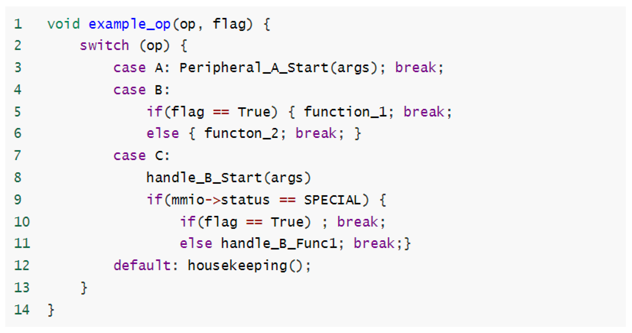
3.3.2. Model-Coverage Task

Currently, there is no clear literature indicating what types of inputs can effectively increase model coverage or help find hardware behavior-related code branches. We draw inspiration from some black-box fuzzing methods [8]. Inputs that can trigger hardware behavior are often based on communication protocols or special commands, and these inputs have many similar segments in text [8], such as machine code for behavior triggering and command fields in protocols. We refer to these text segments as interesting text. Additionally, some different hardware behaviors are triggered by the same function or similar instructions, or they are in close proximity to one another in the code (e.g., lines 8 and 11 in Figure 2). Therefore, we believe that seeds that have already discovered hardware behaviors or contain more interesting text are more likely to trigger other similar hardware behaviors and reach related branches. Therefore, in the model-coverage task, we allocate computing resources based on the number of hardware behaviors discovered by seeds and attempt to include more interesting text in the seeds.
First, we utilize various new models to represent different peripheral device behaviors. In this paper, models generated by model re-instantiation during emulator operation and stored in the model pool are referred to as new models. It is important to note that these new models are discovered after emulator initialization. Models established during the initialization process, which are independent of seeds, are not taken into account. The number of model re-instantiation attempts is denoted as s u m r e . The maximum number of instantiation attempts is M A X _ M E _ I N S T A . There are three scenarios for new models: (1) QEMU crashes, stalls, skips, etc., (2) QEMU does not crash and s u m r e < M A X _ M E _ I N S T A , (3) QEMU does not crash and s u m r e = M A X _ M E _ I N S T A . There are many reasons for scenarios (1) and (3). For example, P2IM does not take into account DMA interactions, and these instructions are skipped, potentially causing exceptions. In addition, some inputs may be inherently infeasible for the firmware, as certain firmware functionalities may only accept particular peripheral instructions. This could lead to exceeding the re-instantiation limit or causing errors. Therefore, we define the models generated in scenarios (1) and (3) as invalid or error models, while those generated in scenario (2) are valid models.
Specifically, if a seed discovers a valid model, we consider it more likely to discover similar models and detect related code paths, so we increase the computing resources for these seeds. However, suppose a seed discovers an erroneous model. In that case, we decrease the computing resources for these seeds for the following three reasons: (1) the model corresponds to invalid hardware behavior and does not help the fuzzer discover more paths or improve model coverage, (2) the model may cause crashes unrelated to the firmware, leading the fuzzer to produce false positives, mistaking them for genuine firmware crashes, and (3) the model involves multiple re-instantiations, leading to time wastage due to repeated invocations. If a seed discovers both a new model and new paths, then the seed is similar to the case C we presented in P2, indicating that these seeds have even greater value for further testing. We allocate additional computing resources to these models.
Second, we modified AFL’s seed splicing algorithm to increase the presence of interested text fragments in seeds. As mentioned earlier, seeds that have discovered valid models are believed to contain interesting text. We make these seeds more likely to be selected by the splicing algorithm, therefore increasing the overall mathematical expectation of interested text occurrences.

3.4. Seed Schedule

The improved seed schedule in this paper consists of two components: the power schedule and the seed selection. The power schedule determines how many test cases each seed generates, while the seed selection determines their priority. As discussed in Section 3.3, this paper transforms Problems P1 and P2 into path-coverage tasks and model-coverage tasks, respectively. Following the design principles outlined in Section 3.3, we combine these two tasks to design the seed schedule algorithm. Specifically, the power schedule simultaneously addresses both path-coverage tasks and model-coverage tasks, while seed selection is divided into two parts: the favorite queue for the path-coverage task and seed splicing for the model-coverage task.
Algorithm 1 illustrates the overall process of the seed scheduling algorithm we designed. Q is a queue consisting of all effective seeds. Lines 8–24 represent a complete round of fuzzing, where PHASESWITCH() is the phase-switching function corresponding to the segmented fuzzing approach in the path-coverage task. Before each round of testing, PHASESWITCH() determines whether to switch phases. The function GETASEED() is a probabilistic function that randomly selects a seed, with a bias towards selecting seeds from the FAVORITEQUEUE. The function CALSCORE() is the main component of the power schedule algorithm. It calculates the performance score P t for each seed, which determines the number of inputs generated by the seed. As shown in line 11, each seed i will generate k inputs. We denote the set of inputs generated by each seed i Q as T i , where each input generated by i is denoted as t T i . The complete set of inputs generated by all seeds is represented as T = ( T 1 , T 2 , , T | Q | ) . The generation process of input t is manifested through multiple rounds of loops. Specifically, as shown in lines 12–25, each seed iterates k times, and in each iteration, seed i undergoes one mutation to generate an input t. In total, k mutations are performed, and the emulator executes them. CRASH represents the discovery of an error, which is then recorded in the set X. INTERESTING indicates that the framework finds the input t interesting, and it will be recorded as a new seed. Finally, SPLICING() represents the seed splicing algorithm. SPLICING() splices the text from other seeds onto seed i for ϵ 1 times to increase the quantity of interesting text.
Algorithm 1 Seed Schedule
Require: 
I n i t i a l S e e d S
  1:
   X =
  2:
   Q = S
  3:
  if  Q =   then
  4:
     Add random file to Q
  5:
  end if
  6:
  repeat
  7:
      P H A S E S W I T C H ( ) //Part of the power schedule
  8:
     repeat
  9:
         i = G E T A S E E D ( Q , F A V O R I T E Q U E U E )
  10:
        P T = C A L S C O R E ( i ) //Part of the power schedule
  11:
        k = P T C
  12:
       for  m = 0 to ϵ  do
  13:
         for  n = 0 to k ϵ  do
  14:
            t = M U T A T E ( i )
  15:
            r e s = e m u l a t o r ( t )
  16:
           if  r e s = C R A S H  then
  17:
             Add t to X
  18:
           else if  r e s = I N T E R S E T I N G  then
  19:
             Add t to Q
  20:
           end if
  21:
         end for
  22:
          i = S P L I C I N G ( i )
  23:
       end for
  24:
     until Fuzzer completed a round of seed selection
  25:
until Timeout or exit signal
Ensure: 
C r a s h s e t X

3.5. Power Schedule

This section discusses the details of the power schedule.
As described in Section 3.4, the overall fuzzing process is iterative. For the power schedule, the number of test cases generated in each fuzzing iteration is based on the seed’s previous performance. We refer to the impact metric as the metric measuring the performance of seeds during the fuzzing process. These different impact metrics do not have explicit quantifiable relationships, so AFL’s approach is to convert the relevant impact metrics into factors multiplied by the original scores. We followed AFL’s approach to the power schedule, converting the subsequent performances of the two tasks into factors multiplied by the original scores. Consequently, we calculated a factor for each of the path-coverage tasks and the model-coverage task. Additionally, if a seed has not discovered any models, we convert the model-coverage task of these seeds into a fixed factor of less than 1. This factor of less than 1 represents the reduction of computing power from the path-coverage task to the model-coverage task. Thus, we obtain the final expression for P T :
P T ( i ) = P A ( i ) · f a c t o r 0 · f a c t o r 1
f a c t o r 0 represents the factor obtained from the conversion of the impact metric related to the path-coverage task, while f a c t o r 1 represents the factor obtained from the conversion of the impact metric related to the model-coverage task. Below, we present the calculation process for the factors related to the path coverage and model-coverage tasks.

3.5.1. Path-Coverage Task

In the power schedule, the path-coverage task follows a segmented fuzzing approach, which consists of two phases: the rapid depth exploration phase and the flexible breadth exploration phase. The algorithm framework utilizes PHASESWITCH() function to transition between these two phases. As described in Section 3.3.1, the rapid depth exploration phase focuses primarily on seeds with less overlap in corresponding paths, enabling rapid coverage of more paths. On the other hand, the flexible breadth exploration phase aims to balance computational resources by emphasizing testing on paths that were less covered during the rapid depth exploration phase, serving as a complement to the rapid depth exploration phase.
Next, we explain how we measure the quality of seeds. For a seed i, we refer to the number of times a seed i has already been tested as the fuzz level, denoted by l ( i ) , and the number of times the path corresponding to seed i has been executed by other inputs t as the testing frequency, denoted by f ( i ) . f ( i ) denotes the degree of repetition within the testing path. To facilitate understanding of f ( i ) , we define a function t r a c e ( i , t ) . If the path corresponding to i has been executed by t, t r a c e ( i , t ) outputs 1; otherwise, it outputs 0. For example, in Figure 1, where i = ‘110’ and t = ‘111’, we have t r a c e ( i , t ) = 1 , as they both only executed line 2 and did not execute lines 3–5. Hence:
f ( i ) = t i n T t r a c e ( i , t )
We consider l ( i ) and f ( i ) as impact metrics for the path-coverage task. Therefore, f a c t o r 0 is a function of l ( i ) and f ( i ) , with different expressions in the two phases. We will now explain them separately.
Rapid Depth Exploration Phase: In this stage, we allocate computational resources to some high-quality seeds as much as possible. Specifically, we use l ( i ) and f ( i ) to measure seed quality. A higher l ( i ) suggests that the fuzzer deems the seed’s performance in previous fuzzing iterations superior, thus warranting continued attention. Conversely, a higher value of f ( i ) indicates that the seed has repeatedly tested more code branches with other inputs, suggesting that such seeds lack the necessity for further testing at the current stage. Therefore, specifically, in this stage, the expression for f a c t o r 0 is as follows:
f a c t o r 0 ( i ) = λ 0 2 l ( i ) f ( i )
where λ 0 ( 0 , 1 ] is a constant representing the initial score assigned to newly discovered seeds. This value can be adjusted according to the task requirements; for example, in certain fuzzing tasks, there may be a focus on testing specific paths (e.g., using a predetermined seed corpus instead of a random one). If a seed has a high l ( i ) and a low f ( i ) , it will result in a larger f a c t o r 0 , leading to the allocation of more computational resources. For instance, in the scenario described in Problem P1, after obtaining the seed “100” in the second round of testing, the seed “110” corresponds to the path “1X*” being tested multiple times, resulting in f (“110”) = 17. In this case, the f a c t o r 0 for seed “110” in the second round is calculated as 2 1 17 , meaning its fuzzy test cases for this round will be 27 · 2 17 , rounded to 3. Conversely, the f a c t o r 0 for more valuable seed “100” is 2 0 1 , resulting in its fuzzy test cases for this round being 27 · 1 1 , equal to 27. It is evident that this strategy significantly reduces computational resource wastage. These seeds with larger l ( i ) and smaller f ( i ) are like probes, continuously selected by the fuzzer, and less likely to repeatedly test paths that have been tested by other inputs. This helps rapidly increase testing depth and efficiently explore program branches. However, since the average value of f ( i ) is not computed in this stage, we are unaware of which seeds are actually being overly tested. Therefore, it is necessary to switch stages after a certain period.
Flexible Breadth Exploration Phase: In this stage, the focus is on seeds that have been skipped or tested less during the rapid depth exploration phase. After a certain number of rounds of testing, the probe seeds have generated an excessive number of test cases, diminishing the value of further testing. However, many other seeds, either due to a high f ( i ) or the pruning process (described in Section 3.5.3), have a small l ( i ) and consequently a low f a c t o r 0 and thus no testing opportunities. Therefore, in this phase, the fuzzer reduces the computational resource allocation for some probe seeds and increases it for other seeds, attempting to explore paths skipped in the rapid depth exploration phase. To determine which seeds should have their testing frequency reduced, we set a threshold μ representing the average testing frequency. μ is computed as:
μ = i Q f ( i ) | Q |
We believe that seeds exceeding the threshold should have their allocation of computing resources reduced, while other seeds should have their allocation of computing resources increased rapidly. Therefore, the f a c t o r 0 for this phase is computed as:
f a c t o r 0 ( i ) = μ 2 · f ( i ) f ( i ) > μ λ 0 · 2 l ( i ) f ( i ) μ
where λ 0 ( 0 , 1 ] aligns with the rapid depth exploration phase and represents the initial allocation of computational resources for certain seeds. For seeds whose testing frequency exceeds the threshold μ , their f a c t o r 0 will be rapidly reduced, with a greater proportion exceeding, resulting in less computational resource allocation. Conversely, for seeds with a testing frequency below the threshold, their f a c t o r 0 will exponentially increase, aiding these under-tested seeds in quickly reaching the average value.
Phase Switch Strategy: The phase switch strategy is executed at the position of line 7 in Algorithm 1. The fuzzer decides whether or not to perform a phase switch before the start of each round of fuzzing. Approximately, we assume that if the fuzzer has not discovered any new paths within a certain period, it is considered to be in a state of stagnation. If the stagnation occurs in the rapid depth exploration phase, it indicates that the probe seeds have been thoroughly tested, and it is unlikely to discover new paths in the short term. If the stagnation occurs in the flexible breadth exploration phase, it suggests that most seeds have reached the average testing frequency, necessitating a re-concentration of computational resources on specific seeds. Therefore, we believe that a fuzzer in stagnation needs to change phases.
Algorithm 2 shows the detailed process of the phase switch strategy. We define the time interval from the start of the fuzzer’s operation to the current moment as the execution time, denoted by T, and the time interval from the last detection of a new path by the fuzzer to the current moment is defined as the stagnation time, denoted by S. The minimum time threshold is denoted as T m i n , ensuring that PHASESWITCH() does not begin at the start of testing but only after a certain period has elapsed. We use DEPTH to denote the rapid depth exploration phase and BREADTH to denote the flexible breadth exploration phase, collectively referred to as phase mode. We set proportion thresholds r 0 and r 1 to measure the ratio of stagnation time, with 1 > r 0 > r 1 . When r 0 · T S , indicating that the stagnation time exceeds a certain proportion of the total time, it suggests that the fuzzer has completed sufficient testing in the rapid depth exploration phase, and then the fuzzer will switch to the flexible breadth exploration phase. When the fuzzer enters the new phase and discovers new paths, S will quickly decrease. r 1 ensures that the fuzzer will not immediately switch phases again but will test for a period in the new phase before being able to switch back to the rapid depth exploration phase. Because the flexible breadth exploration phase supplements the rapid depth exploration phase, our design ensures that the overall duration of the flexible breadth exploration phase is slightly shorter.
Algorithm 2 PHASESWITCH()
Require: 
T 2 · T m i n , S T m i n
  1:
if  S r 0 · T   then
  2:
        P H A S E _ M O D E = B R E A D T H
  3:
else if  S r 1 · T  then
  4:
        P H A S E _ M O D E = D E P T H
  5:
end if
Ensure: 
P H A S E _ M O D E

3.5.2. Model-Coverage Task

As described in Section 3.3.2, in the power schedule, the model-coverage task calculates f a c t o r 1 based on the following two principles: (1) increasing the allocation of computational resources to seeds that have discovered valid models, and (2) decreasing the allocation of computational resources to seeds that have discovered flawed models.
For a seed i, each input t T i generated by mutation is executed in the emulator. If a hardware behavior pattern is detected during the execution of t, we refer to the model stored in the model pool that t discovered as m t . The set of all valid models generated by the input t is denoted v m t , where v m t m t , and the set of all error models is denoted e m t , where e m t m t . For each input t, the number of valid models it generates is denoted as v t , where v t = | v m t | , and the number of error models is denoted as e t , where e t = | e m t | . Since our focus is on the seed i that generates t, the total number of corresponding valid models and error models for seed i, denoted v i and e i , are computed as:
v i = t = 1 | T i | v t
e i = t = 1 | T i | e t
We consider v i and e i as the impact metrics for the model-coverage task, so f a c t o r 1 is a function of v i and e i . The expression for f a c t o r 1 is as follows:
f a c t o r 1 = λ 1 2 v i 2 χ e i + δ
λ 1 < 1 is a constant representing the initial score for all seed model-coverage tasks. For seeds i that do not involve hardware behavior models, their f a c t o r 1 = λ 1 , resulting in P t ( i ) < P A ( i ) . This reflects the transfer of computational resources from these seeds. χ 1 is the model correction parameter we define. In the process of model re-instantiation, most error models occur in groups, so their quantity is usually greater than the actual effect. χ is related to the size of the M A X _ M E _ I N S T A parameter in the re-instantiation process. In our task, χ is set to 1 3 . δ is an additional constant of interest, typically set δ = 0 in our task. However, if a seed discovers both new paths and effective models, we pay extra attention to these seeds and set δ = 1 . When these types of seeds are just discovered, λ 1 2 v i 2 χ e i is relatively small, and the additional constant δ helps them quickly gain the attention of the fuzzer.

3.5.3. Edge Trimming

Edge trimming refers to a normalization process in the calculation of the power schedule. Edge trimming is divided into two parts: factor trimming and final score P T trimming.
Factor Trimming: Since the calculation of f a c t o r 0 and f a c t o r 1 both involve exponential variables, to prevent an exponential explosion that would cause certain seeds to generate too many test cases, we set a maximum value, f m a x , for the factors and trim them before they contribute to the final score calculation. The expressions for trimming f a c t o r 0 and f a c t o r 1 are as follows:
f a c t o r 0 , 1 ( i ) = M I N ( f a c t o r 0 , 1 ( i ) , f m a x )
P t Trimming: The trimming of P T is designed to filter out excessively low P T values. We set a minimum value for P T , denoted as f m i n . During the execution of the fuzzer, we aim to have the fuzzer skip input t with too low P T to improve efficiency.
The reason for this is primarily that these seeds have a short effective testing time: A very low P T means that the number of test cases k = | T i | generated by seed i is too small. We denote the sum of the time taken by the fuzzer to mutate i to generate input files and the initialization time of the emulator as t i n i t ( i ) . We observed that the initialization time could be longer than the total execution time of all t generated by i, i.e., t i n i t ( i ) > k · t m ( i ) (where t m ( i ) is detailed in Section 2.1.2, Formula (1)), which is a waste of resources. Therefore, we choose to temporarily refrain from testing these seeds until switching to a new phase. For example, seeds that are temporarily not tested in the rapid depth exploration phase will inevitably have a low testing frequency, and these seeds will obtain a higher P T in the flexible breadth exploration phase for testing. The formula for trimming P T is as follows:
P T ( i ) = P T P T ( i ) f m i n 0 P T ( i ) < f m i n

3.6. Seed Selection

This section explores the details of seed selection, which controls the priority of fuzzing. In this paper, the seed selection strategy consists of two main parts: the favorite queue for the path-coverage task and seed splicing for the model-coverage task.

3.6.1. Favorite Queue

The favorite queue is related to the GETASEED (Q, FAVORITEQUEUE) function in Algorithm 1 line 9. Similar to the AFL algorithm, the GETASEED() function prioritizes the selection of seeds from the favorite queue for testing. We have improved the way AFL selects seeds to enter the favorite queue, giving priority to high-quality seeds.
Specifically, the fuzzer will follow three steps to select a favorite seed: (1) compare the l ( i ) of seed i and select the one with the smaller l ( i ) as the favorite seed, (2) if the l ( i ) values are equal, compare the f ( i ) of seed i and select the one with the smaller f ( i ) as the favorite seed, (3) if both l ( i ) and f ( i ) are equal, then calculate f a v _ f a c t o r ( i ) as AFL does.
The significance of steps (1) and (2) is as follows: If two seeds cover the same path branch, priority is given to the seed with fewer test times and lower test repetition. This helps to quickly select probe seeds. As l ( i ) increases, if seed i continues to be repeatedly chosen for fuzzing, it indicates that the seed possesses irreplaceable testing path branches, which evidently align with our requirement for high-quality seeds.

3.6.2. Seed Splicing

Seed splicing corresponds to the SPLICING function in line 22 of Algorithm 1.
As discussed in Section 3.3.2, we believe that seed j that has discovered more valid models is likely to contain more interesting texts and can help the fuzzer discover more valid models. Therefore, we prefer the fuzzer to prioritize seed j with larger v j and smaller e j . To quickly select such seeds j during splicing, we have defined a skip probability p ( j ) . p ( j ) represents the probability that seed j is skipped and another seed j is selected as the splicing target for seed i. The expression for p ( j ) is as follows:
p ( j ) = γ 2 χ e j 2 v j
where γ < 1 is a constant. γ represents the base probability, which is the probability that a seed that has not discovered any models will be skipped. The larger γ is, the more the fuzzer focuses on model discovery. In this paper, we set γ = 0.5 . χ is the same as in Section 3.5.2 (Formula (10)). For the splicing target seed j of seed i, the more valid models seed j has discovered, the smaller p ( j ) is, and the less likely seed j is to be skipped. Conversely, seeds j with too many error models are more likely to be ignored. Seed i tends to splice with seeds j, which have discovered more valid models.
The overall process of seed splicing is illustrated in Algorithm 3. The splicing function takes a seed i as input. The CONTENT(i) function retrieves all the text from seed i and stores it as b u f i . The fuzzer randomly selects a splice target seed j and calculates p ( j ) (line 3). It then uses random number generation to determine if seed j is skipped. If j is skipped, the fuzzer will reselect a new seed j and repeat the process until a new seed is not skipped (line 4). Subsequently, the MERGE() function selects text segments from both b u f i and b u f j , respectively, and concatenates them to form a new segment of text b u f i j (line 6). The SEED() function then converts b u f i j into a new seed i 1 (line 7).
Algorithm 3 SPLICING()
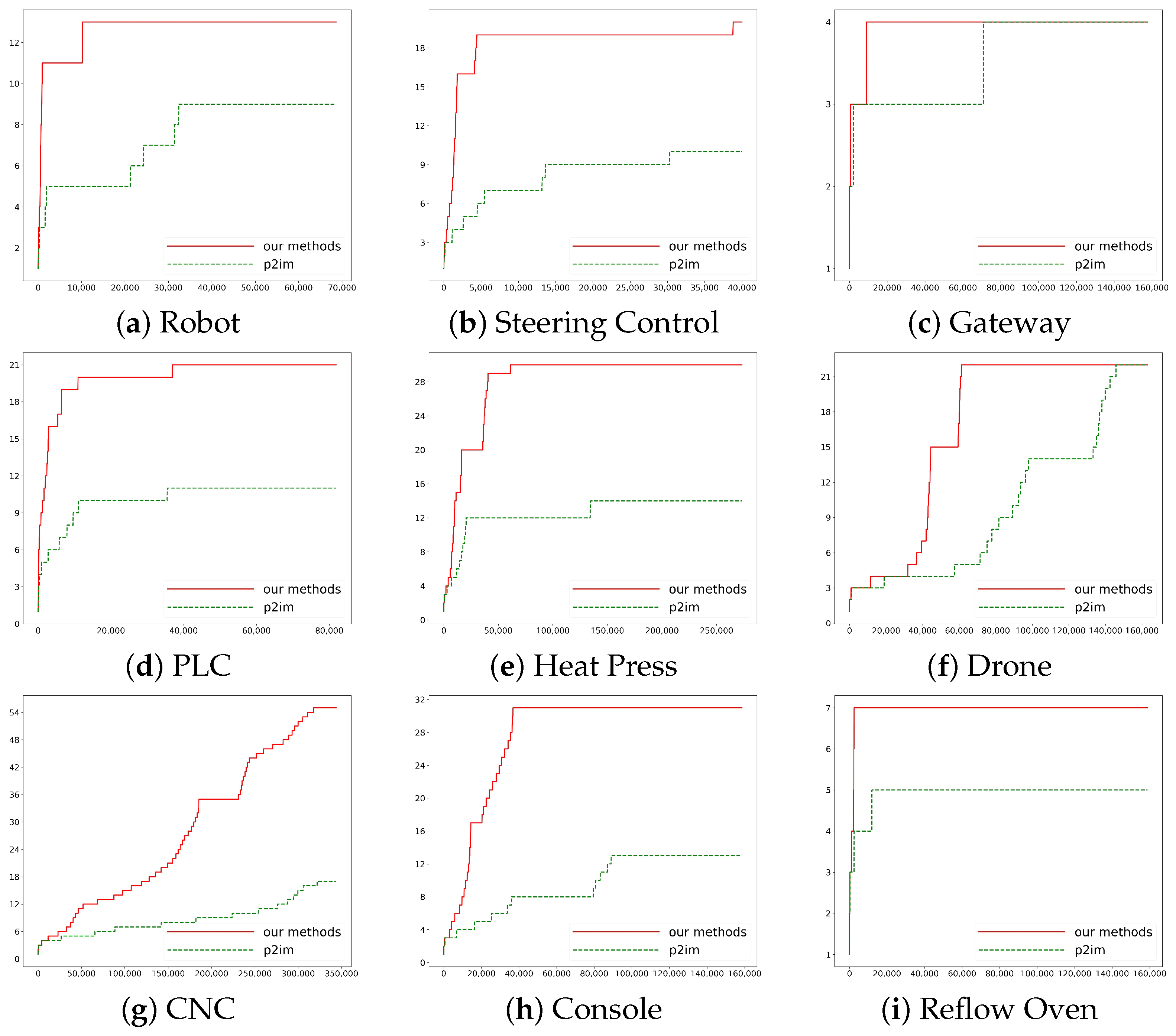
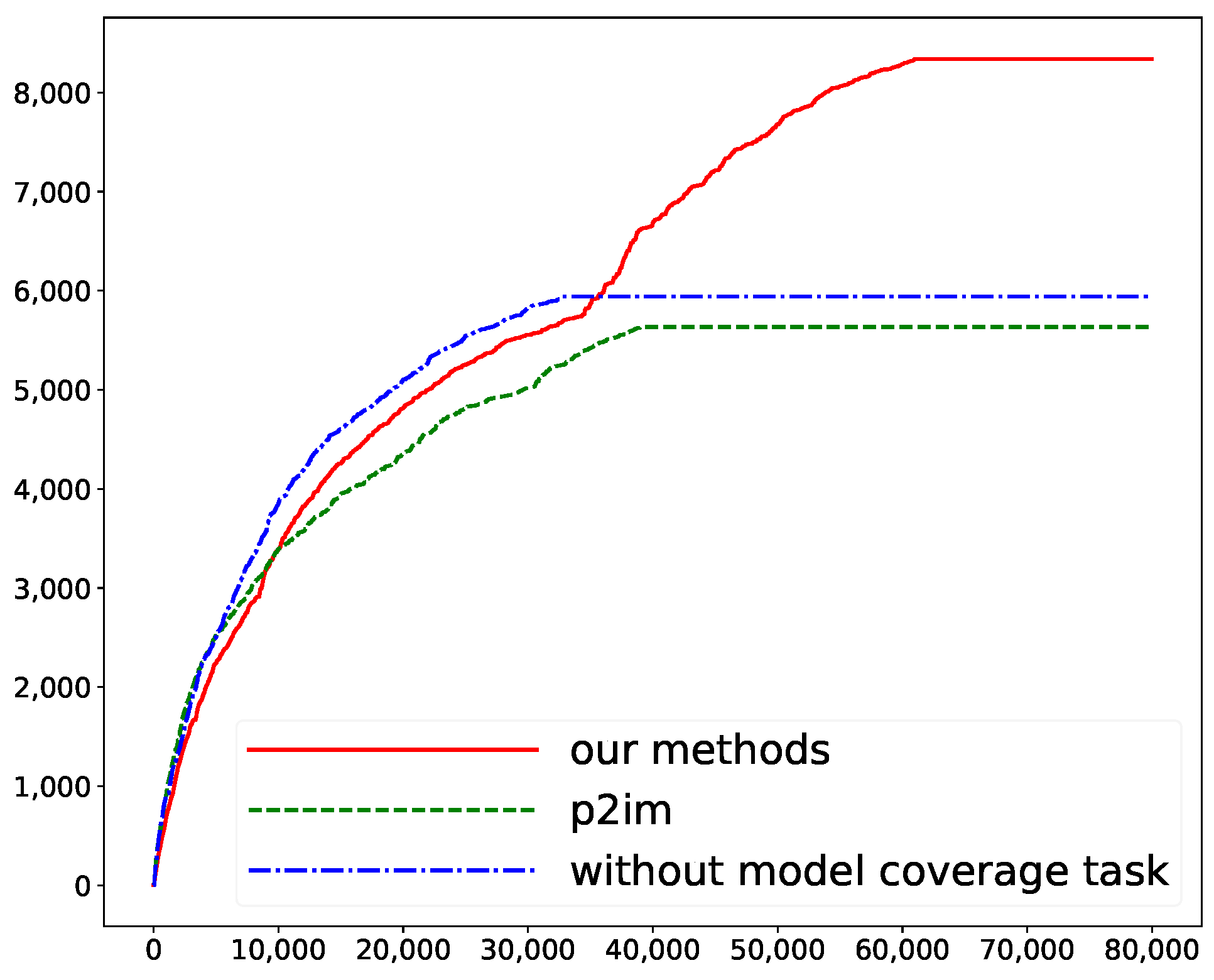
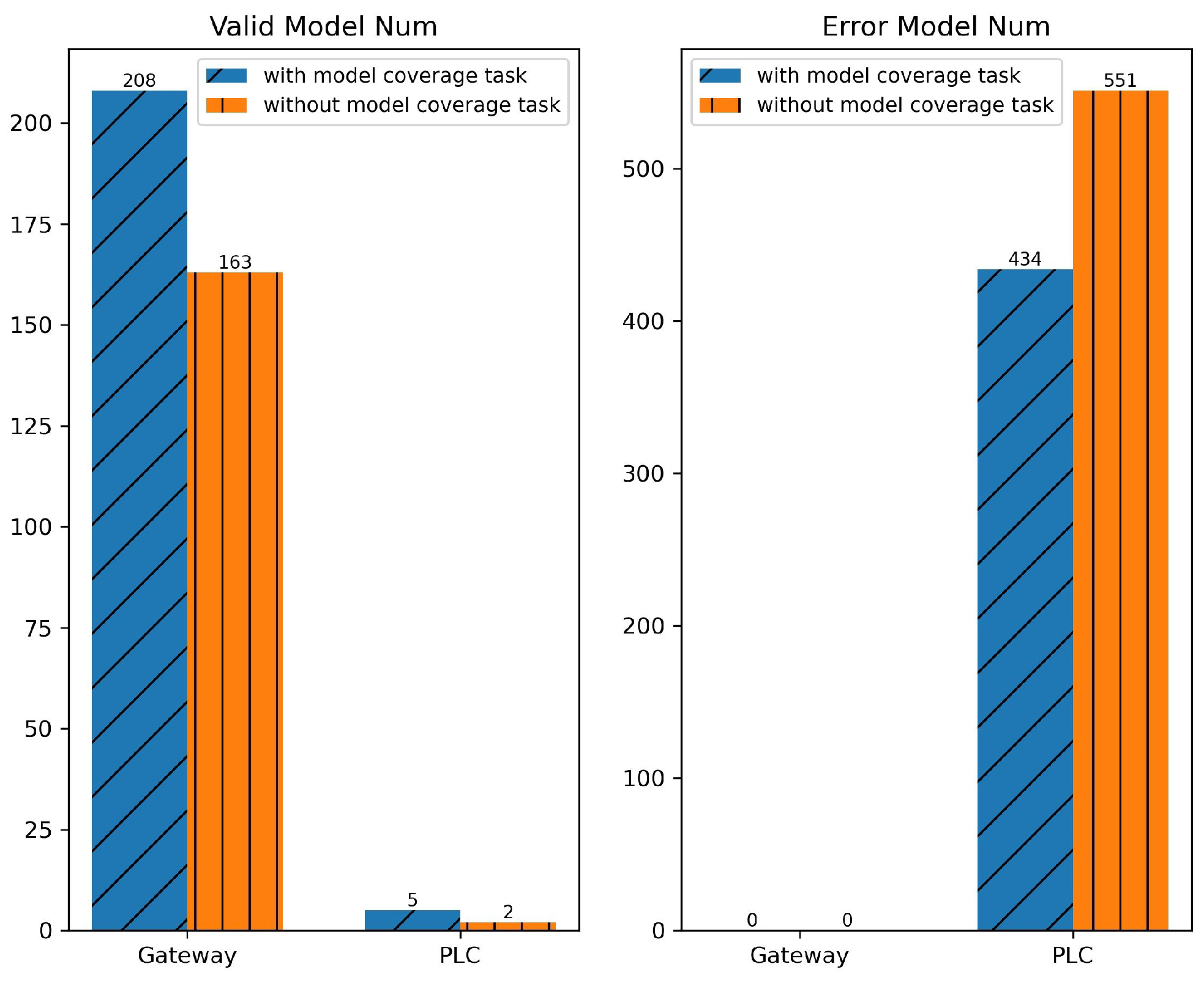
Require: 
i
  1:
b u f i = C O N T E N T ( i )
  2:
repeat
  3:
      j = R A N D S E L E C T ( Q )
  4:
until  p ( j ) r a n d o m ( 0 , 1 )
  5:
b u f j = C O N T E N T ( j )
  6:
b u f i j = M E R G E ( b u f i , b u f j )
  7:
i 1 = S E E D ( b u f i j )
Ensure: 
i 1

4. Evaluation

4.1. Experimental Design
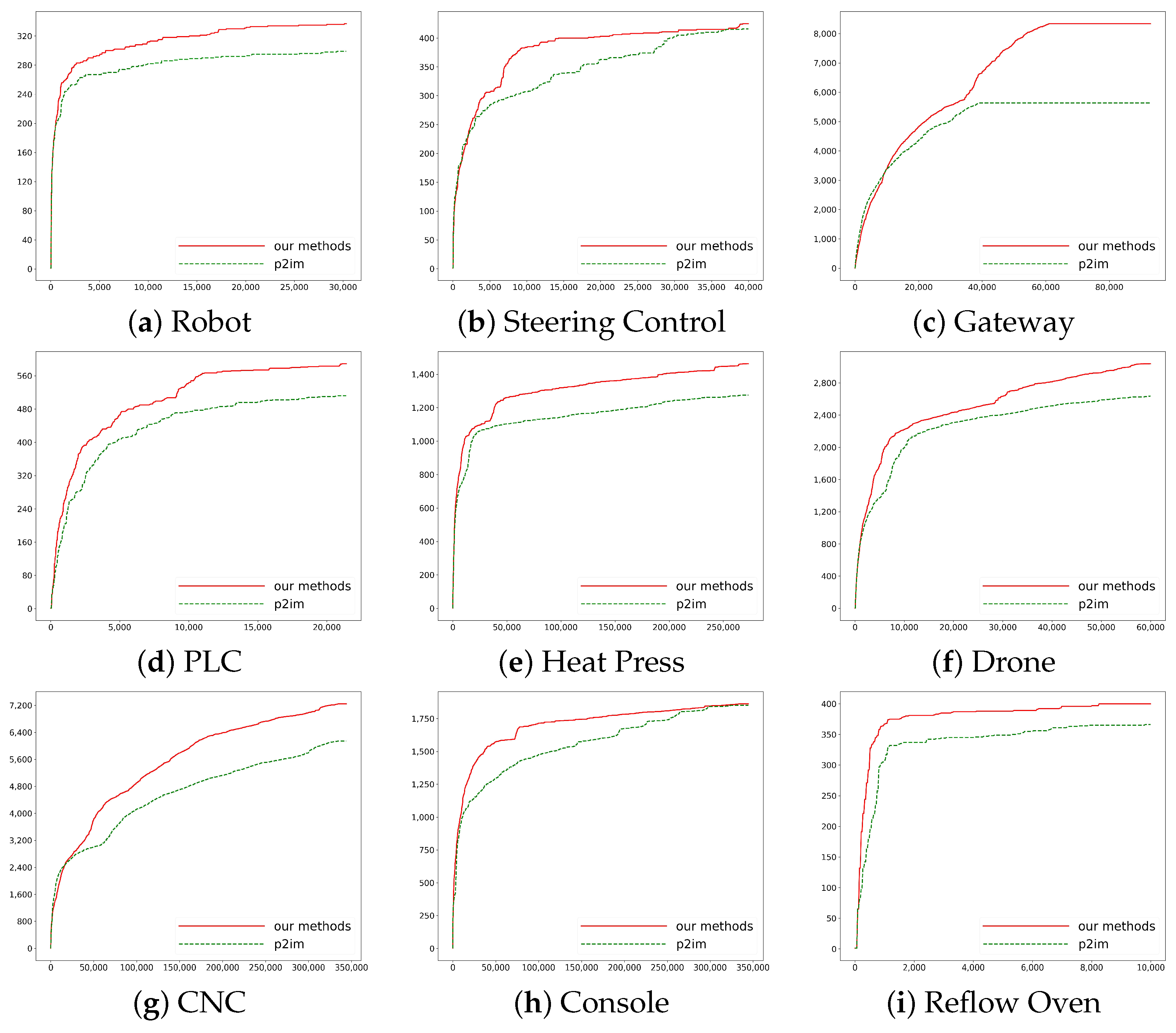
Firmware Selection: The firmware we used is from the P2IM [30] research (the P2IM method proposes both a rehosting method and provides an open-source dataset). We selected nine firmware from the P2IM open-source firmware library for our experiments. These pieces of firmware include Robot, Steering Control (self-driving vehicle), Gateway, PLC (Programmable Logic Controller), Heat Press, Drone, CNC (Grbl milling controller), Console, and Reflow Oven (commercial reflow oven controller). They cover four MCUs and four operating systems.
Experimental Environment: The code base for our system operates on Ubuntu 16.04. We have modified our experimental code based on AFL version 2.06b and QEMU version 2.3.50. Our system runs on a computer with moderate computing power: Quad-Core Intel® Core™i9-10980XE CPU @ 3.00 GHz with 8 GB of RAM, used to evaluate the efficiency improvements of our method.
Experimental Methodology: To validate the effectiveness of our approach, we designed the following two experiments regarding the issues outlined in Section 3.1:
Experiment 1: Addressing Problem P1, we aim to verify whether our method effectively enhances the overall efficiency of fuzzing. We compare our approach (DCG algorithm + P2IM rehosting framework) with the original P2IM method (AFL + P2IM rehosting framework). Fuzzing is conducted on the same firmware using both methods simultaneously on the same computer. Each firmware undergoes fuzzing for at least 12 h until the number of detected paths stabilizes for both methods. As described in Section 2.3, we measure the overall efficiency based on the number of discovered paths.
Experiment 2: Addressing Problem P2, we aim to validate the existence of Problem 2 and verify the effectiveness of our designed model-coverage task algorithm. We conducted fuzzing using three different methods on two firmware instances with a significant number of hardware behaviors: our method, the P2IM method, and our method without the model-coverage task and related strategies. We conducted five tests on each of the two firmware instances, with each test running for at least 12 h until the number of detected paths stabilized. In this experiment, we simultaneously measured model coverage and path coverage to evaluate the experimental results.

4.2. Results

The results of Experiment 1 are shown in Figure 4 and Figure 5.
Figure 4 compares our method and P2IM in terms of the number of paths discovered over time on nine different firmware. The horizontal axis represents time (in seconds), and the vertical axis represents the number of paths. Except for the initial short period, our method consistently achieved higher path coverage faster on each firmware instance. As shown in Figure 4c, our approach has achieved a maximum increase of 47.9% in path coverage. In Section 5, we will elaborate on why our method did not show an advantage during the initial period.
Figure 5 illustrates the maximum path depth reached by the seeds. The horizontal axis represents time (in seconds), and the vertical axis represents the maximum path depth among all seeds at each moment. Similar to Figure 4, except for the initial short period, our method exhibited better performance on all nine firmware instances.
The results of Experiment 2 are shown in Figure 6 and Figure 7.
Figure 6 displays the results of fuzzing on the Gateway firmware using our method, the P2IM method, and our method without the model-coverage task and related strategies. Compared to the P2IM method, the method without the model-coverage task and related strategies only improved path coverage by a mere 5.4%. However, once the model-coverage task and related strategies were incorporated, the improvement in final path coverage became significantly evident. We will also explain in Section 5 why our method did not show an advantage and even slightly underperformed during the initial short period.
Figure 7 depicts the statistics of the average number of models obtained from five times of fuzzing on the PLC and Gateway firmware instances using our method and the P2IM method. On the left are the average numbers of effective models, while on the right are the average numbers of erroneous models. In the two pieces of firmware shown in the figure, our approach resulted in a 27.6% increase in the number of valid models and a 21.2% reduction in the number of error models.

5. Discussion

5.1. Result Analysis

The results of Experiment 1 indicate that our designed DCGFuzz effectively enhances the overall efficiency of fuzzing. The results of Experiment 2 demonstrate that our method effectively improves model coverage and, by discovering hardware behavior-related paths, also enhances path coverage.
Here, we discuss the reasons why our method exhibited slightly inferior performance during the initial period:
In Figure 4 and Figure 5, on some firmware instances, such as shown in Figure 4g, it was only after some time that our method started to be better. We think that at the beginning of fuzzing, seed selection tends to be essentially random due to the small values of f ( i ) and l ( i ) . As a result, our method does not differ significantly from the original AFL method, except for some additional time consumption caused by our algorithm. Only when the values of f ( i ) and l ( i ) become relatively large over time does our method show its advantages.
In Figure 6, compared to the method without the model-coverage task, our method initially exhibits inferior performance. We think this is because the model-coverage task and related algorithms shift some computing resources to hardware behavior-related paths. As described in Section 3.3.2, these paths typically require more test cases to discover critical branches (e.g., Case C in Figure 2). Therefore, compared to other conventional paths (e.g., Case B in Figure 2), these critical branches require more computing resources. This is reflected in the initially lower number of discovered paths in the figure. However, as the fuzzer learns about these hardware behavior patterns and critical branches, many other paths are rapidly discovered (e.g., Line 10 and Line 11 in Figure 2). This is reflected in the rapid increase in the number of discovered paths later in the figure.

5.2. Method Effectiveness

We discuss the effectiveness of our method from the perspectives of the path-coverage task and model-coverage task, respectively.
Path-Coverage Task: The results in Figure 4 demonstrate that our method reaches a larger maximum path depth (i.e., d ( i ) in Formula (1) in Section 2.1.2) faster, which proves that our strategy of the rapid depth exploration phase does work. The larger maximum path depth reflects the seeds’ greater ability to explore branches, which suggests a higher quality of the seeds selected by our method. Furthermore, the phase-switching strategy also plays an important role. Taking the console firmware as an example (as shown in Figure 4h and Figure 5h), at approximately 50,000 s, the depth of paths detected by the fuzzer remained essentially unchanged. At this point, some probe seeds had reached a sufficient number of test iterations. Then, around 70,000 s, the fuzzer encountered a bottleneck in the number of discovered paths, indicating that all probe seeds had essentially reached the desired testing objectives. Subsequently, the fuzzer executed the phase-switching strategy, after which the number of paths began to increase again rapidly. We think that for most firmware, the rapid depth exploration phase is sufficient to explore most paths. However, in the case of firmware such as Console, which has more detail and complex paths, the Flexible Breadth Exploration and Phase Switch strategies effectively complement the Rapid Depth Exploration to achieve better results.
In addition, our method demonstrates more significant effectiveness on firmware with a greater number of code branches. We believe this is because our power schedule primarily focuses on seed exploration frequency, f ( i ) . When fuzzing firmware with more paths, the fuzzer is more likely to select probe seeds with fewer repeated branches among them, resulting in higher testing efficiency.
Model-coverage task: As shown in Figure 6, our method indeed discovers more paths on firmware which has more hardware behaviors. However, solely relying on improvements in the path-coverage task did not yield the anticipated efficiency enhancement (as indicated by the blue line in Figure 6). This also indirectly reflects the issue we proposed in Problem P2, namely that certain hardware behavior-related paths are prone to being ignored, which exists in some firmware instances.
On the other hand, as illustrated in Figure 7, our designed model-coverage task effectively increases the number of valid models while reducing the number of error models. As described in Section 3.3.2, valid models help us discover hardware behavior-related paths, while error models represent wasted computing resources. Therefore, the results in Figure 7 indicate that the fuzzer successfully reallocates computing resources to more valuable paths.
In general, we consider that our designed model-coverage task and related algorithms have met our expectations.

5.3. Future Work

In this paper, we proposed the DCGFuzz framework, which we believe theoretically can be applicable to different types of rehosting frameworks. Currently, we have only experimented with the pattern-based MMIO modeling approach, which we deemed most suitable. Our next objective is to explore the feasibility of our design approach on other different types of rehosting frameworks.

6. Conclusions

We design DCGFuzz, a new approach to improve the efficiency of fuzzing by changing the way computational resources are allocated. Our method improves the overall efficiency of fuzzing and finds some hardware behavior-related paths more easily by considering both the path-coverage task and the model-coverage task, as well as allocating the computational resources dynamically and uniformly through the seed schedule. Finally, we experimentally demonstrated the effectiveness of our approach and achieved a maximum increase of 47.9% in path coverage and an improvement of 27.6% in effective model coverage.

Author Contributions

Conceptualization, Y.L.; methodology, Y.W.; software, Y.W.; validation, Y.W.; formal analysis, Y.W.; investigation, Y.L.; resources, Y.L.; data curation, Y.W.; writing—original draft preparation, Y.W.; writing—review and editing, Y.W.; visualization, Y.W.; supervision, Y.L.; project administration, Y.L.; funding acquisition, Y.L. All authors have read and agreed to the published version of the manuscript.

Funding

This research was partially supported by the National Key Research and Development Program (No. 2023YFB2504800), Henan Science and Technology Major Project (No. 221100240100), SongShan Laboratory Pre-Research Project (No. YYJC042022016), Shanghai Sailing Program (No. 21YF1413800).

Data Availability Statement

Dataset available on request from the authors.

Conflicts of Interest

The authors declare no conflict of interest.

References

  1. Zhu, P.; Hu, J.; Li, X.; Zhu, Q. Using blockchain technology to enhance the traceability of original achievements. IEEE Trans. Eng. Manag. 2021, 70, 1693–1707. [Google Scholar] [CrossRef]
  2. Bobde, Y.; Narayanan, G.; Jati, M.; Raj, R.S.P.; Cvitić, I.; Peraković, D. Enhancing Industrial IoT Network Security through Blockchain Integration. Electronics 2024, 13, 687. [Google Scholar] [CrossRef]
  3. Czeczot, G.; Rojek, I.; Mikołajewski, D. Autonomous Threat Response at the Edge Processing Level in the Industrial Internet of Things. Electronics 2024, 13, 1161. [Google Scholar] [CrossRef]
  4. Li, Y.; Liu, W.; Liu, Q.; Zheng, X.; Sun, K.; Huang, C. Complying with ISO 26262 and ISO/SAE 21434: A Safety and Security Co-Analysis Method for Intelligent Connected Vehicle. Sensors 2024, 24, 1848. [Google Scholar] [CrossRef] [PubMed]
  5. Zhang, X.; Upton, O.; Beebe, N.L.; Choo, K.R. Iot Botnet Forensics: A Comprehensive Digital Forensic Case Study on Mirai Botnet Servers. Forensic Sci. Int. Digit. Investig. 2020, 32, 300926. [Google Scholar] [CrossRef]
  6. Garcia, L.; Brasser, F.; Cintuglu, M.H.; Sadeghi, A.R.; Mohammed, O.A.; Zonouz, S.A. Hey, My Malware Knows Physics! Attacking PLCs with Physical Model Aware Rootkit. In Proceedings of the NDSS, San Diego, CA, USA, 26 February–1 March 2017; pp. 1–15. [Google Scholar]
  7. Boone, A. Why Is Traditional IT Security Failing to Protect the IoT? 2018. Available online: https://www.timesys.com/security/traditional-it-security-failing-to-protect-iot/ (accessed on 25 January 2022).
  8. Feng, X.; Sun, R.; Zhu, X.; Xue, M.; Wen, S.; Liu, D.; Nepal, S.; Xiang, Y. Snipuzz: Black-box fuzzing of iot firmware via message snippet inference. In Proceedings of the 2021 ACM SIGSAC Conference on Computer and Communications Security, Virtual Event, 15–19 November 2021; pp. 337–350. [Google Scholar]
  9. Chen, J.; Diao, W.; Zhao, Q.; Zuo, C.; Lin, Z.; Wang, X.; Lau, W.C.; Sun, M.; Yang, R.; Zhang, K. IoTFuzzer: Discovering Memory Corruptions in IoT Through App-based Fuzzing. In Proceedings of the NDSS, San Diego, CA, USA, 18–21 February 2018. [Google Scholar]
  10. Böhme, M.; Manès, V.J.; Cha, S.K. Boosting fuzzer efficiency: An information theoretic perspective. In Proceedings of the 28th ACM Joint Meeting on European Software Engineering Conference and Symposium on the Foundations of Software Engineering, Virtual Event, 8–13 November 2020; pp. 678–689. [Google Scholar]
  11. Wang, J.; Song, C.; Yin, H. Reinforcement learning-based hierarchical seed scheduling for greybox fuzzing. In Proceedings of the Network and Distributed Systems Security (NDSS) Symposium 2021, San Diego, CA, USA, 21–24 February 2021. [Google Scholar]
  12. Rawat, S.; Jain, V.; Kumar, A.; Cojocar, L.; Giuffrida, C.; Bos, H. VUzzer: Application-aware Evolutionary Fuzzing. In Proceedings of the NDSS, San Diego, CA, USA, 26 February–1 March 2017; Volume 17, pp. 1–14. [Google Scholar]
  13. Yue, T.; Wang, P.; Tang, Y.; Wang, E.; Yu, B.; Lu, K.; Zhou, X. EcoFuzz: Adaptive Energy-Saving greybox fuzzing as a variant of the adversarial Multi-Armed bandit. In Proceedings of the 29th USENIX Security Symposium (USENIX Security 20), Boston, MA, USA, 12–14 August 2020; pp. 2307–2324. [Google Scholar]
  14. Yun, J.; Rustamov, F.; Kim, J.; Shin, Y. Fuzzing of Embedded Systems: A Survey. ACM Comput. Surv. 2022, 55, 137. [Google Scholar] [CrossRef]
  15. Kim, M.; Kim, D.; Kim, E.; Kim, S.; Jang, Y.; Kim, Y. Firmae: Towards large-scale emulation of iot firmware for dynamic analysis. In Proceedings of the Annual Computer Security Applications Conference, Austin, TX, USA, 7–11 December 2020; pp. 733–745. [Google Scholar]
  16. Zheng, Y.; Davanian, A.; Yin, H.; Song, C.; Zhu, H.; Sun, L. FIRM-AFL: High-Throughput greybox fuzzing of IoT firmware via augmented process emulation. In Proceedings of the 28th USENIX Security Symposium (USENIX Security 19), Santa Clara, CA, USA, 14–16 August 2019; pp. 1099–1114. [Google Scholar]
  17. Scharnowski, T.; Bars, N.; Schloegel, M.; Gustafson, E.; Muench, M.; Vigna, G.; Kruegel, C.; Holz, T.; Abbasi, A. Fuzzware: Using Precise MMIO Modeling for Effective Firmware Fuzzing. In Proceedings of the 31st USENIX Security Symposium (USENIX Security 22), Boston, MA, USA, 10–12 August 2022; pp. 1239–1256. [Google Scholar]
  18. Zalewski, M. American Fuzzy Lop (AFL) Fuzzer. 2015, p. 33. Available online: http://lcamtuf.coredump.cx/afl/ (accessed on 5 December 2019).
  19. Hertz, J.; Newsham, T. TriforceAFL. AFL Qemu Fuzzing with Full-System Emulation. QEMU Fuzzing with Full-System Emulation. 2019. Available online: https://github.com/nccgroup/TriforceAFL (accessed on 11 March 2023).
  20. Bellard, F. QEMU, a fast and portable dynamic translator. In Proceedings of the USENIX Annual Technical Conference, FREENIX Track, Anaheim, CA, USA, 10–15 April 2005; Volume 41, pp. 10–5555. [Google Scholar]
  21. Quynh, N.A.; Vu, D.H. Unicorn: Next generation cpu emulator framework. In Proceedings of the BlackHat USA, Las Vegas, NV, USA, 1–6 August 2015; Volume 476. [Google Scholar]
  22. Gustafson, E.; Muench, M.; Spensky, C.; Redini, N.; Machiry, A.; Fratantonio, Y.; Balzarotti, D.; Francillon, A.; Choe, Y.R.; Kruegel, C.; et al. Toward the analysis of embedded firmware through automated re-hosting. In Proceedings of the 22nd International Symposium on Research in Attacks, Intrusions and Defenses (RAID 2019), Beijing, China, 23–25 September 2019; pp. 135–150. [Google Scholar]
  23. Costin, A.; Zarras, A.; Francillon, A. Automated dynamic firmware analysis at scale: A case study on embedded web interfaces. In Proceedings of the 11th ACM on Asia Conference on Computer and Communications Security, Xi’an, China, 30 May–3 June 2016; pp. 437–448. [Google Scholar]
  24. Clements, A.A.; Gustafson, E.; Scharnowski, T.; Grosen, P.; Fritz, D.; Kruegel, C.; Vigna, G.; Bagchi, S.; Payer, M. HALucinator: Firmware re-hosting through abstraction layer emulation. In Proceedings of the 29th USENIX Security Symposium (USENIX Security 20), Boston, MA, USA, 12–14 August 2020; pp. 1201–1218. [Google Scholar]
  25. Li, W.; Guan, L.; Lin, J.; Shi, J.; Li, F. From library portability to para-rehosting: Natively executing microcontroller software on commodity hardware. arXiv 2021, arXiv:2107.12867. [Google Scholar]
  26. Maier, D.; Seidel, L.; Park, S. Basesafe: Baseband sanitized fuzzing through emulation. In Proceedings of the 13th ACM Conference on Security and Privacy in Wireless and Mobile Networks, Virtual Event, 8–10 July 2020; pp. 122–132. [Google Scholar]
  27. Seidel, L.; Maier, D.; Muench, M. Forming Faster Firmware Fuzzers. In Proceedings of the USENIX Security, Anaheim, CA, USA, 9–11 August 2023. [Google Scholar]
  28. Liang, J.; Jiang, Y.; Wang, M.; Jiao, X.; Chen, Y.; Song, H.; Choo, K.K.R. Deepfuzzer: Accelerated deep greybox fuzzing. IEEE Trans. Dependable Secur. Comput. 2019, 18, 2675–2688. [Google Scholar] [CrossRef]
  29. Böhme, M.; Pham, V.T.; Roychoudhury, A. Coverage-based greybox fuzzing as markov chain. In Proceedings of the 2016 ACM SIGSAC Conference on Computer and Communications Security, Vienna, Austria, 24–28 August 2016; pp. 1032–1043. [Google Scholar]
  30. Feng, B.; Mera, A.; Lu, L. P2IM: Scalable and hardware-independent firmware testing via automatic peripheral interface modeling. In Proceedings of the 29th USENIX Security Symposium (USENIX Security 20), Boston, MA, USA, 12–14 August 2020; pp. 1237–1254. [Google Scholar]
  31. Lyu, C.; Ji, S.; Zhang, C.; Li, Y.; Lee, W.H.; Song, Y.; Beyah, R. MOPT: Optimized mutation scheduling for fuzzers. In Proceedings of the 28th USENIX Security Symposium (USENIX Security 19), Santa Clara, CA, USA, 14–16 August 2019; pp. 1949–1966. [Google Scholar]
  32. Pham, V.T.; Böhme, M.; Roychoudhury, A. Aflnet: A greybox fuzzer for network protocols. In Proceedings of the 2020 IEEE 13th International Conference on Software Testing, Validation and Verification (ICST), Porto, Portugal, 23–27 March 2020; IEEE: New York, NY, USA, 2020; pp. 460–465. [Google Scholar]
  33. Stephens, N.; Grosen, J.; Salls, C.; Dutcher, A.; Wang, R.; Corbetta, J.; Shoshitaishvili, Y.; Kruegel, C.; Vigna, G. Driller: Augmenting fuzzing through selective symbolic execution. In Proceedings of the NDSS, San Diego, CA, USA, 21–24 February 2016; Volume 16, pp. 1–16. [Google Scholar]
  34. Neugass, H.; Espin, G.; Nunoe, H.; Thomas, R.; Wilner, D. VxWorks: An interactive development environment and real-time kernel for Gmicro. In Proceedings of the Eighth TRON Project Symposium, IEEE Computer Society, Tokyo, Japan, 26–27 November 1991; pp. 196–197. [Google Scholar]
  35. Sastry, D.C.; Demirci, M. The QNX operating system. Computer 1995, 28, 75–77. [Google Scholar]
  36. Hardin, T.; Scott, R.; Proctor, P.; Hester, J.; Sorber, J.; Kotz, D. Application memory isolation on ultra-Low-powerMCUs. In Proceedings of the 2018 USENIX Annual Technical Conference (USENIX ATC 18), Boston, MA, USA, 11–13 July 2018; pp. 127–132. [Google Scholar]
  37. Sun, Z.; Feng, B.; Lu, L.; Jha, S. OAT: Attesting operation integrity of embedded devices. In Proceedings of the 2020 IEEE Symposium on Security and Privacy (SP), San Diego, CA, USA, 18–20 May 2020; IEEE: New York, NY, USA, 2020; pp. 1433–1449. [Google Scholar]
  38. Seshadri, A.; Perrig, A.; Van Doorn, L.; Khosla, P. SWATT: Software-based attestation for embedded devices. In Proceedings of the IEEE Symposium on Security and Privacy, Berkeley, CA, USA, 9–12 May 2004; IEEE: New York, NY, USA, 2004; pp. 272–282. [Google Scholar]
  39. Zaddach, J.; Bruno, L.; Francillon, A.; Balzarotti, D. AVATAR: A Framework to Support Dynamic Security Analysis of Embedded Systems’ Firmwares. In Proceedings of the NDSS, San Diego, CA, USA, 27 February 27–3 March 2014; Volume 14, pp. 1–16. [Google Scholar]
  40. Kammerstetter, M.; Platzer, C.; Kastner, W. Prospect: Peripheral proxying supported embedded code testing. In Proceedings of the 9th ACM Symposium on Information, Computer and Communications Security, Kyoto, Japan, 4–6 June 2014; pp. 329–340. [Google Scholar]
  41. Yu, J.; Kim, J.; Yun, Y.; Yun, J. Poster: Combining Fuzzing with Concolic Execution for IoT Firmware Testing. In Proceedings of the 2023 ACM SIGSAC Conference on Computer and Communications Security, Copenhagen, Denmark, 26–30 November 2023; pp. 3564–3566. [Google Scholar]
  42. Qasem, A.; Shirani, P.; Debbabi, M.; Wang, L.; Lebel, B.; Agba, B.L. Automatic vulnerability detection in embedded devices and firmware: Survey and layered taxonomies. ACM Comput. Surv. (CSUR) 2021, 54, 25. [Google Scholar] [CrossRef]
  43. Aschermann, C.; Schumilo, S.; Blazytko, T.; Gawlik, R.; Holz, T. REDQUEEN: Fuzzing with Input-to-State Correspondence. In Proceedings of the NDSS, San Diego, CA, USA, 24–27 February 2019; Volume 19, pp. 1–15. [Google Scholar]
  44. Fioraldi, A.; Maier, D.; Eißfeldt, H.; Heuse, M. AFL++: Combining incremental steps of fuzzing research. In Proceedings of the 14th USENIX Workshop on Offensive Technologies (WOOT 20), Virtual Event, 11 August 2020. [Google Scholar]
  45. Zhu, X.; Wen, S.; Camtepe, S.; Xiang, Y. Fuzzing: A survey for roadmap. ACM Comput. Surv. (CSUR) 2022, 54, 1–36. [Google Scholar] [CrossRef]
  46. Li, W.; Ruan, J.; Yi, G.; Cheng, L.; Luo, X.; Cai, H. PolyFuzz: Holistic Greybox Fuzzing of Multi-Language Systems. In Proceedings of the 32nd USENIX Security Symposium (USENIX Security 23), Anaheim, CA, USA, 9–11 August 2023; pp. 1379–1396. [Google Scholar]
  47. Binosi, L.; Rullo, L.; Polino, M.; Carminati, M.; Zanero, S. Rainfuzz: Reinforcement-Learning Driven Heat-Maps for Boosting Coverage-Guided Fuzzing. In Proceedings of the 12th International Conference on Pattern Recognition Applications and Methods-ICPRAM, Lisbon, Portugal, 22–24 February 2023; pp. 39–50. [Google Scholar]
  48. Gan, S.; Zhang, C.; Chen, P.; Zhao, B.; Qin, X.; Wu, D.; Chen, Z. GREYONE: Data flow sensitive fuzzing. In Proceedings of the 29th USENIX Security Symposium (USENIX Security 20), Boston, MA, USA, 12–14 August 2020; pp. 2577–2594. [Google Scholar]
  49. She, D.; Shah, A.; Jana, S. Effective seed scheduling for fuzzing with graph centrality analysis. In Proceedings of the 2022 IEEE Symposium on Security and Privacy (SP), San Francisco, CA, USA, 22–26 May 2022; IEEE: New York, NY, USA, 2022; pp. 2194–2211. [Google Scholar]
  50. Wang, J.; Duan, Y.; Song, W.; Yin, H.; Song, C. Be sensitive and collaborative: Analyzing impact of coverage metrics in greybox fuzzing. In Proceedings of the 22nd International Symposium on Research in Attacks, Intrusions and Defenses (RAID 2019), Beijing, China, 23–25 September 2019; pp. 1–15. [Google Scholar]
  51. Herrera, A.; Gunadi, H.; Magrath, S.; Norrish, M.; Payer, M.; Hosking, A.L. Seed selection for successful fuzzing. In Proceedings of the 30th ACM SIGSOFT International Symposium on Software Testing and Analysis, Virtual Event, 11–17 July 2021; pp. 230–243. [Google Scholar]
  52. Fasano, A.; Ballo, T.; Muench, M.; Leek, T.; Bulekov, A.; Dolan-Gavitt, B.; Egele, M.; Francillon, A.; Lu, L.; Gregory, N.; et al. Sok: Enabling security analyses of embedded systems via rehosting. In Proceedings of the 2021 ACM Asia Conference on Computer and Communications Security, Hong Kong, China, 7–11 June 2021; pp. 687–701. [Google Scholar]
  53. Corteggiani, N.; Camurati, G.; Francillon, A. Inception:System-Wide security testing of Real-World embedded systems software. In Proceedings of the 27th USENIX Security Symposium (USENIX Security 18), Baltimore, MD, USA, 15–17 August 2018; pp. 309–326. [Google Scholar]
  54. Koscher, K.; Kohno, T.; Molnar, D. SURROGATES: Enabling Near-Real-Time dynamic analyses of embedded systems. In Proceedings of the 9th USENIX Workshop on Offensive Technologies (WOOT 15), Washington, DC, USA, 10–11 August 2015. [Google Scholar]
  55. Baezner, M.; Robin, P. Stuxnet; Technical Report; ETH Zurich: Zurich, Switzerland, 2017. [Google Scholar]
  56. Chen, D.D.; Woo, M.; Brumley, D.; Egele, M. Towards automated dynamic analysis for linux-based embedded firmware. In Proceedings of the NDSS, San Diego, CA, USA, 21–24 February 2016; Volume 1, p. 1. [Google Scholar]
  57. Zhou, W.; Guan, L.; Liu, P.; Zhang, Y. Automatic firmware emulation through invalidity-guided knowledge inference. In Proceedings of the 30th USENIX Security Symposium (USENIX Security 21), Vancouver, BC, Canada, 11–13 August 2021; pp. 2007–2024. [Google Scholar]
  58. Wu, Y.; Zhang, T.; Jung, C.; Lee, D. DEVFUZZ: Automatic Device Model-Guided Device Driver Fuzzing. In Proceedings of the 2023 IEEE Symposium on Security and Privacy (SP), San Francisco, CA, USA, 22–24 May 2023; pp. 3246–3261. [Google Scholar]
  59. Harrison, L.; Vijayakumar, H.; Padhye, R.; Sen, K.; Grace, M. PARTEMU: Enabling Dynamic Analysis of Real-WorldTrustZone Software Using Emulation. In Proceedings of the 29th USENIX Security Symposium (USENIX Security 20), Boston, MA, USA, 12–14 August 2020; pp. 789–806. [Google Scholar]
  60. Miller, C. Fuzz by Number: More Data about Fuzzing Than You Ever Wanted to Know. Proceedings of the CanSecWest. 2008. Available online: https://fuzzinginfo.wordpress.com/wp-content/uploads/2012/05/cmiller_cansecwest2008.pdf (accessed on 7 April 2024).
Figure 1. Example function of CGFs fuzzing process.
Electronics 13 01433 g001
Figure 2. Example functions for problem definition.
Electronics 13 01433 g002
Figure 3. The framework diagram of our method.
Electronics 13 01433 g003
Figure 4. The changes in the number of paths discovered during fuzzing processes across different firmware.
Electronics 13 01433 g004
Figure 5. The variation in path depth during fuzzing processes across different firmware.
Electronics 13 01433 g005
Figure 6. The impact of the model-coverage task and related strategies on the number of discovered paths.
Electronics 13 01433 g006
Figure 7. Statistics on the number of models discovered during fuzzing processes in gateway and PLC firmware.
Electronics 13 01433 g007
Disclaimer/Publisher’s Note: The statements, opinions and data contained in all publications are solely those of the individual author(s) and contributor(s) and not of MDPI and/or the editor(s). MDPI and/or the editor(s) disclaim responsibility for any injury to people or property resulting from any ideas, methods, instructions or products referred to in the content.

