Article

An Indoor 3D Positioning Method Using Terrain Feature Matching for PDR Error Calibration

1
Yangtze Delta Region Institute (Quzhou), University of Electronic Science and Technology of China, Quzhou 324003, China
2
School of Information Science and Technology, Southwest Jiaotong University, Chengdu 611756, China
*
Author to whom correspondence should be addressed.
Electronics 2024, 13(8), 1468; https://doi.org/10.3390/electronics13081468
Submission received: 22 February 2024 / Revised: 31 March 2024 / Accepted: 8 April 2024 / Published: 12 April 2024

Abstract

:
Pedestrian Dead Reckoning (PDR) is a promising algorithm for indoor positioning. However, the accuracy of PDR degrades due to the accumulated error, especially in multi-floor buildings. This paper introduces a three-dimensional (3D) positioning method based on terrain feature matching to reduce the influence of accumulated errors in multi-floor scenes. The proposed calibration method involves two steps: motion pattern recognition and position matching-based calibration. The motion pattern recognition aims to detect different motion patterns, i.e., taking the stairs or horizontal walking, from the streaming data. Then, stair entrances and corridor corners are matched with transition points of motion patterns and pedestrian turning points, respectively. After matching, calibration is performed to eliminate the accumulated errors. By carrying out experiments on a two-floor closed-loop path with a walking distance about 145 m, it is shown that this method can effectively reduce the accumulated error of PDR, achieving accurate 3D positioning. The average error is reduced from 6.60 m to 1.37 m.

1. Introduction

Indoor positioning technology is of great significance for location-based services (LBS) and boasts a wide range of applications in our daily lives [1], such as emergency rescue and hospital navigation [2,3,4]. In recent years, with the miniaturization and integration of sensors, inertial navigation positioning technology based on Inertial Measurement Units (IMUs) has been frequently adopted for indoor pedestrian tracking and navigation [5,6]. One of the main implementation methods is the Pedestrian Dead Reckoning (PDR) algorithm [7,8]. However, it inevitably incurs cumulative positioning errors that cannot be mitigated over time. There are two solutions to this problem: one is infrastructure-based methods, and the other is infrastructure-free methods.
The infrastructure-based methods combine UWB [9], Wi-Fi [10], Bluetooth, and other technologies. However, these technologies rely on supporting infrastructure, which entails time-consuming, laborious, and costly large-scale facility installations [11]. Meanwhile, due to the constraints of indoor terrain, the signal is significantly interfered by the multipath effect [12]. Therefore, the infrastructure-based PDR calibration algorithm can hardly be applicated to constrained terrain scenes.
The infrastructure-free PDR calibration method reduces errors through an algorithmic process. A representative method is the zero-velocity update algorithm (ZUPT) [13,14], which is generally suited for foot-based dead reckoning systems. However, Yu et al. proposed that an IMU installed on the feet may be influenced by impacts between the feet and the ground during walking [15]. In contrast, IMUs placed on the waist do not encounter this issue, resulting in higher accuracy for step detection. Meanwhile, Yu et al. compared the effectiveness of pedestrian tracking methods using IMUs placed on the feet, waist, and a handheld smartphone. By conducting walking experiments on three different paths, they concluded that the waist-mounted system exhibits the highest positioning accuracy and stability [15]. The foot-mounted system was most affected by variations in the walking paths. Liu et al. [16] compared the effectiveness of installing inertial sensors on the waist, feet, and knees. Their findings indicated that the gyroscope readings from the waist location provided the most accurate estimation of pedestrian heading. Li et al. [17] designed a magnetic matching-assisted indoor positioning system based on a waist-mounted sensor array. However, the performance of this method will decrease due to the magnetic interference generated by metal objects in modern architecture. In the case of avoiding external interference, Shi et al. [18] proposed a PF-SLAM indoor pedestrian location algorithm based on a feature point map without prior knowledge of the map. However, the accuracy of the constructed feature points depends on the amount of data and the accuracy of the device, which bring a high cost and instability for positioning. Note that only the building structure will remain constant, and it is presented on the map. Zizzo et al. [19] integrated a map-based particle filter to correct the errors in the inertial navigation algorithm. However, the particle filter algorithm operates too slowly to run in real time. The method of setting landmarks on the map for matching can help to calibrate the positioning error [20]. Ghaoui et al. [21] designed a landmark matching system based on a PDR and a particle filter (PF), achieving a high-precision indoor positioning result. Although these methods can achieve better performance in 2D positioning, they cannot achieve 3D positioning, which has a wider range of application scenarios.
Yang et al. [22] extended the indoor positioning problem to three dimensions by combining it with multiple sensors. Zhao et al. [23] combined inertial sensing devices with a barometer for 3D positioning. They effectively eliminated the accumulated altitude estimation error caused by the inherent drift of IMU sensors through the complementary filters and error compensation algorithms. Nam et al. [24] proposed using multiple sensors to detect terrain features, in order to identify unique landmark information. They utilized this landmark information to correct positioning drift errors in systems without infrastructure. However, the methods mentioned above that combine inertial sensors and barometers will inevitably have a certain degree of error. Experiments designed by Yang et al. indicated that even on level ground, atmospheric pressure fluctuates with pedestrian movement, leading to estimation errors [22]. Additionally, atmospheric pressure is significantly influenced by weather conditions such as temperature and humidity, impacting the measurement results and height accuracy. Regular calibration is necessary to ensure precision, with different calibration parameters required at varying altitudes. The error of the above methods is essentially derived from the influence of the environment. In order to avoid the influence of the external environment, Xie et al. [25] proposed a foot-mounted pedestrian navigation system with an IMU. The experiment results show its high accuracy in 2D positioning and altitude estimation. The method they proposed relies on the pre-obtained motion pattern of a pedestrian, that is, the zero-velocity detection method and lateral-velocity restriction method are applied when a pedestrian walks horizontally in a 2D plane, and the stair step height correction method is applied when a pedestrian takes stairs. Under the condition of continuous 3D positioning, the motion pattern of a pedestrian will change, thus introducing an extra accumulated error which is hard to eliminate by the previous methods.
Fortunately, the change of motion patterns of people also provides extra information about their position in the building. Therefore, in this paper, a 3D positioning scheme is proposed to obtain the positional information of a pedestrian with the aid of motion pattern recognition. Note that the stair entrance is the position where the pedestrian’s motion pattern changes, and it marks a change in altitude. Moreover, indoor corners contain clear position and direction information, which can be used to identify turns in behavior [26]. Therefore, we could use the terrain features of the building, i.e., indoor stair entrances and the corners of the corridor, to calibrate the error, achieving accurate 3D positioning. The positions of all indoor terrain feature points can be obtained through engineering drawings. The Terrain Feature Matching Calibration (TFMC) method is as follows: (1) The acceleration data collected by inertial sensors are divided into data under the pattern of taking the stairs and horizontal walking through the motion pattern recognition. (2) Through the reckoning of pedestrian planar trajectory and altitude, the stair path and horizontal path can be recovered. For the stair path, stair entrances are matched with transition points of motion patterns. For the horizontal path, corners of the corridor are matched with pedestrian turning points. After matching, position calibration is performed to eliminate the accumulated errors, with further calibration of step length and yaw for the horizontal path. The main contribution of the proposed method lies in its effective reduction of PDR error, and thus it more accurately calibrates pedestrian 3D walking trajectories with the use of IMUs only.
The rest of this paper is structured as follows. First, Section 2 discusses some related work in the paper. Section 3 introduces the Terrain Feature Matching Calibration (TFMC) method under indoor constrained terrain. Section 4 conducts experimental verification and result analysis. Section 5 summarizes the full text.

2. Related Works

2.1. Altitude Estimation

In indoor 3D positioning, the altitude information of a pedestrian is typically obtained through the second-order integration of vertical acceleration data. In addition, some researchers use pattern recognition to assist in height estimation. By extracting time-domain features from the sensor signals as feature vectors, Xia et al. [27] designed an adaptive network-based fuzzy inference system (ANFIS) to identify vertical motion patterns and estimate altitude. Since the algorithm’s solution depends on zero-speed information, it cannot be directly applied to altitude estimation in the scenario of this paper. After extracting the features for motion recognition from the inertial sensor, feature matching is performed by measuring the similarity between features to identify the pedestrian’s motion pattern [28]. Template matching is a general method for determining the similarity between feature vectors [29].
Alaoui et al. [30] utilized a Magnetic and Inertial Measurement Unit (MIMU) to collect data on pedestrian movements indoors. Subsequently, they employed the K-Nearest Neighbors (KNN) algorithm to identify several motion patterns of the pedestrians, including normal walking, going upstairs, going downstairs, and others. Wang et al. [31] investigated the impact of sliding windows on human motion patterns and posture recognition using smartphones. They tested five commonly used machine learning algorithms and concluded that Adaptive Boosting and KNN algorithms were more effective than other methods. Based on the terrain information that corresponds with the motion pattern, the altitude of the pedestrian can be calculated.

2.2. PDR Error Calibration with Feature Matching

For the horizontal walking pattern with no changes in altitude, the horizontal walking path is recovered using the PDR algorithm. It includes three steps: step detection, step length estimation, and yaw estimation. These steps are used to obtain the step length and direction of travel from the starting position in order to calculate the pedestrian’s next moment location [32], as Equation (1) shows:
x i + 1 = x i + S L i s i n θ i y i + 1 = y i + S L i c o s θ i
where S L i and θ i represent the step length and the walking direction, and the ith step ( x i , y i ) is the current position. For step detection, pedestrian walking posture can be detected by setting the peak acceleration threshold and the peak interval threshold to achieve accurate step counting [33]. For step length estimation, Weinberg [34] proposed a famous step length estimation model:
S L = K × a m a x a m i n 4
where a m a x and a m i n represent the maximum and minimum acceleration during the walking process, respectively, and K is model parameter. The heading information is obtained from the second-order integration of the gyroscope’s output angular velocity data. Based on the above work, the PDR algorithm is used to recover the pedestrian path that needs to be calibrated.
When performing terrain feature matching to calibrate PDR error, some indicators are used to measure the similarity between pedestrian trajectories and terrain features, i.e., the Euclidean distance [21] and the correlation coefficient [35]. However, due to the cumulative positioning error, using a single indicator for matching has a high mismatch rate. In this paper, the two indicators are combined for the calibration of PDR.

3. TFMC Method

3.1. Method Overview

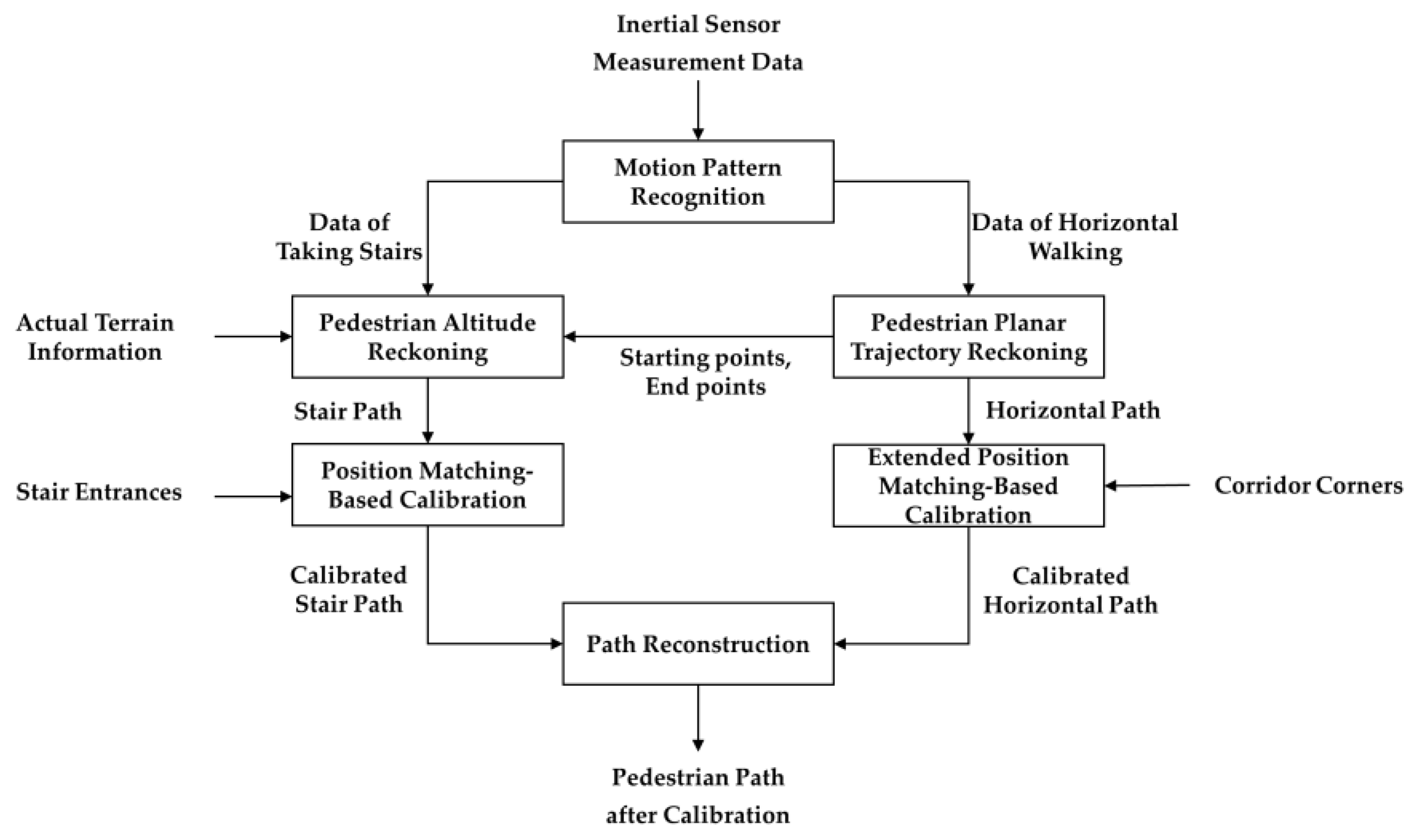
Figure 1 gives an overview of the proposed TFMC method, which includes motion pattern recognition (MPR), pedestrian planar trajectory reckoning (PPTR), pedestrian altitude reckoning (PAR), position matching-based calibration (PMC), and extended position matching-based calibration (EPMC). MPR is applied to divide the acceleration data into the data under the patterns of taking the stairs and horizontal walking. For the data of horizontal walking, PPTR is performed to recover the horizontal path. Then, the starting point and end point of each horizontal path are obtained. Note that between the end point of the previous horizontal path and the starting point of the next horizontal path is the stair path. Based on the data of taking the stairs, actual terrain information, and starting points and end points produced by PPTR, PAR is performed to recover the stair path. Subsequently, the stair path is calibrated by using the method of PMC with the position information of stair entrances. Similarly, the horizontal path is calibrated by using the method of EPMC with the position information of corridor corners. Finally, the calibrated stair path and horizontal path are combined to reconstruct the path, and the calibrated three-dimensional path is obtained.

3.2. Motion Pattern Recognition

The interquartile range (IQR) is a statistical method used to measure the dispersion of data, which is robust against outliers or extreme values. It effectively mitigates the impact of extreme values in acceleration data. Therefore, the IQR is utilized to process the acceleration data [36]. The window size of accelerometer signals is set as 100, and the data of the series are arranged in descending order. The calculation formula of the IQR is as follows:
Q I Q R = Q 3 Q 1
where Q 3 and Q 1 are the median values of the first 50 and the last 50 data, respectively.
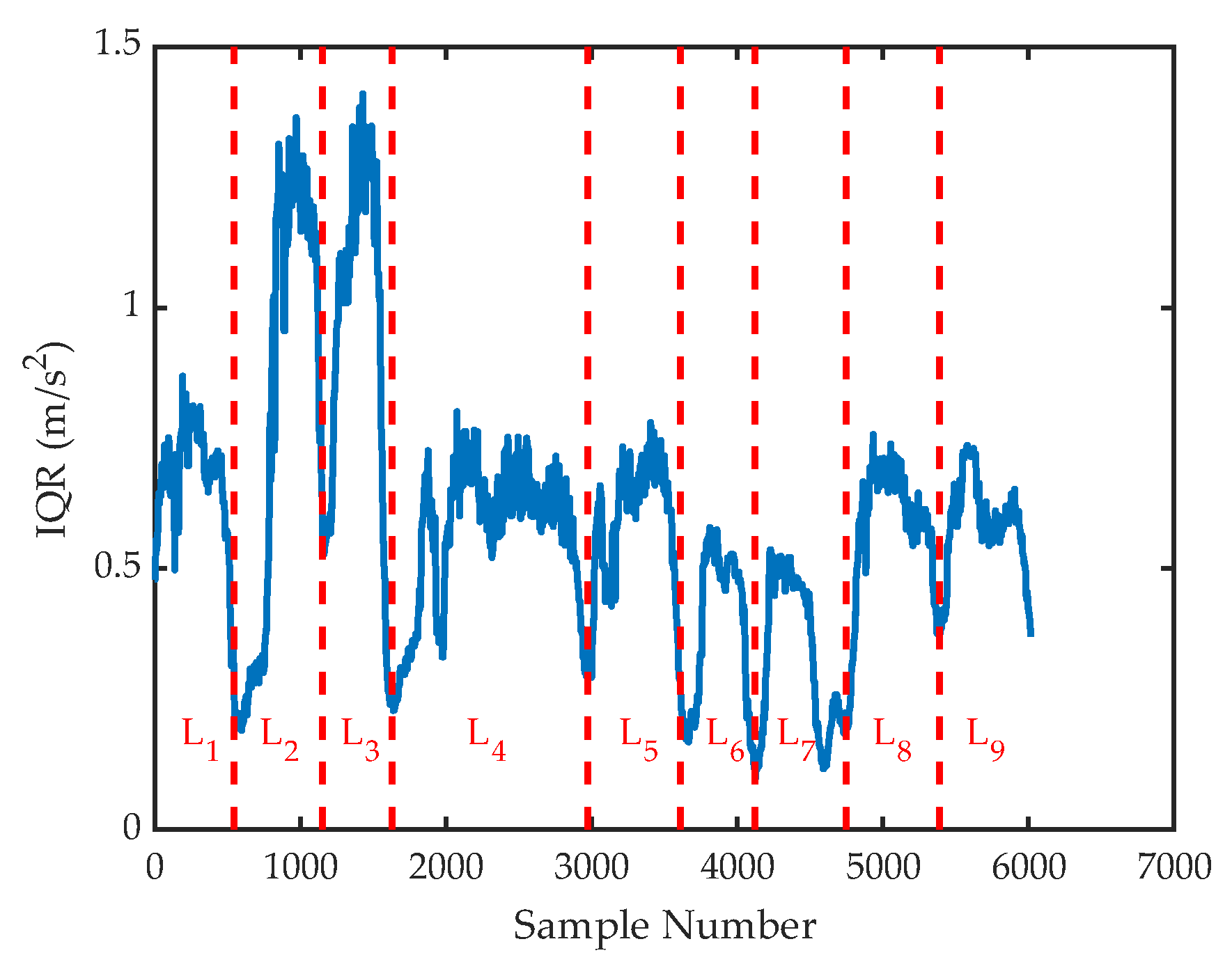
It can be seen from the indoor building structure that when a pedestrian walks in a constrained terrain, the pedestrian will turn significantly at the corner of the corridor to enter the next constrained terrain area. A pedestrian will first pass through a corner of the corridor before reaching the stair entrance. Therefore, the turning time point can be used to divide the IQR data, and the complex walking process of a pedestrian can be divided into several parts containing single motion patterns. With the sliding window detection method, if the window continuously detects coordinate points that meet the threshold conditions, then the last coordinate point is regarded as a corridor turning point. The division of IQR is shown in Figure 2.
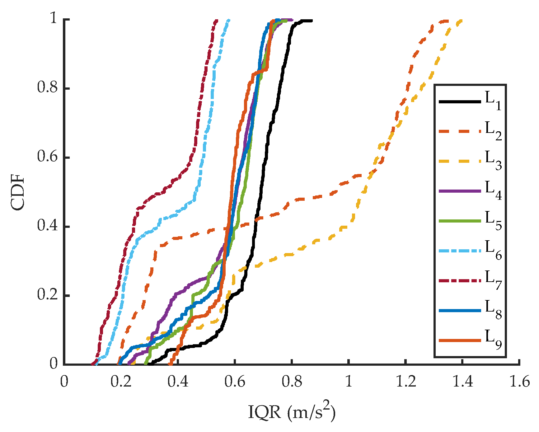
According to the figure, the pedestrian walking process is divided into nine parts. These parts are roughly categorized based on the size of their IQR values. The cumulative probability distribution curve is shown in Figure 3.
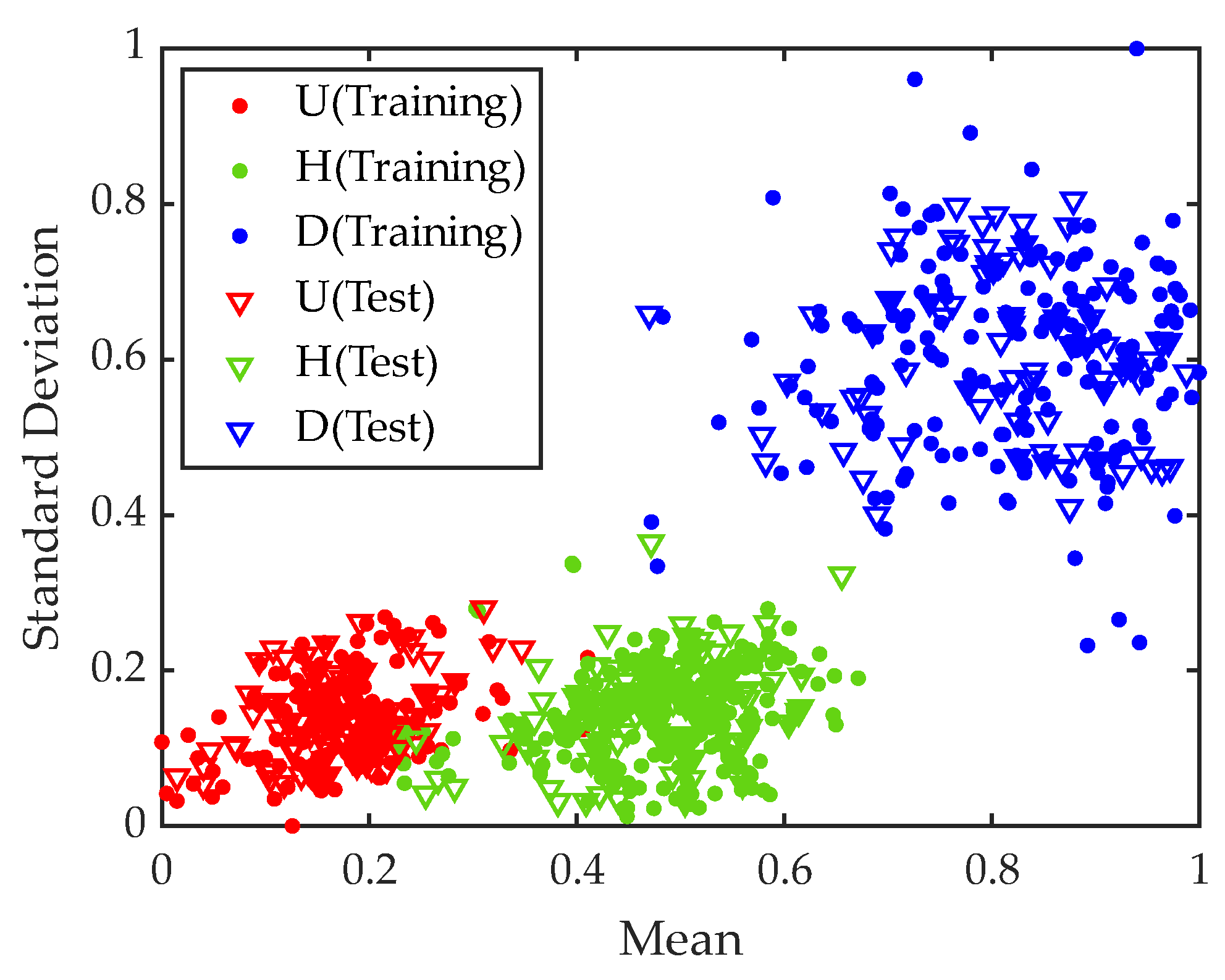
The mean and standard deviations of the IQR data are selected as the characteristic variables, and standard deviation is computed by:
S T D = 1 N 1 i = 1 N ω i ω ¯ 2
where ω i is the sample data, ω ¯ is the sample average, and 
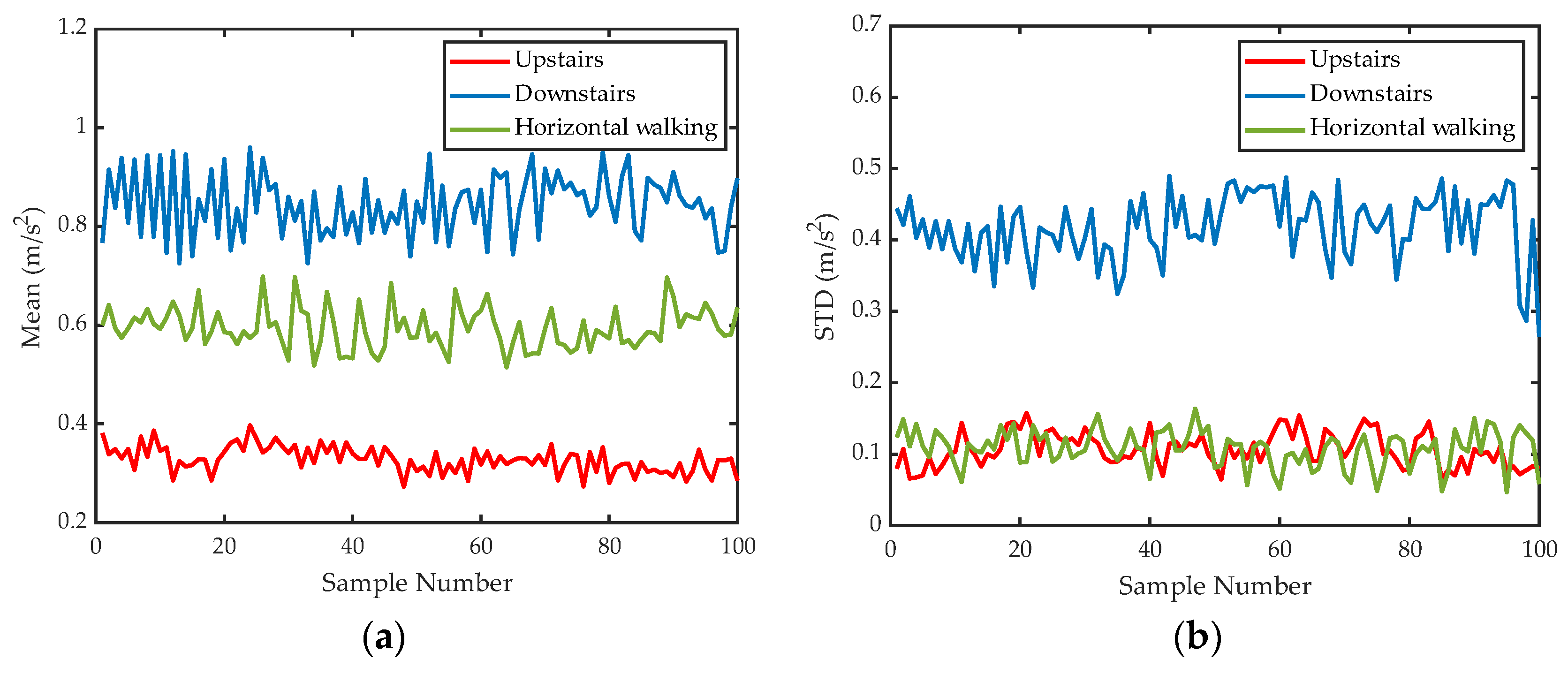
N denotes the sample number. As depicted in Figure 4, acceleration data for the three motion patterns were collected utilizing an inertial sensor, comprising 100 groups for each pattern.
Analysis of the time-domain characteristics of the IQR shows a distinct ascending trend for mean values when comparing the patterns of going upstairs, walking horizontally, and going downstairs. Additionally, the standard deviation of going downstairs is significantly larger than that of walking horizontally or going upstairs. The mean and standard deviations of the IQR are composed of pattern feature points that can be used to characterize the motion pattern.
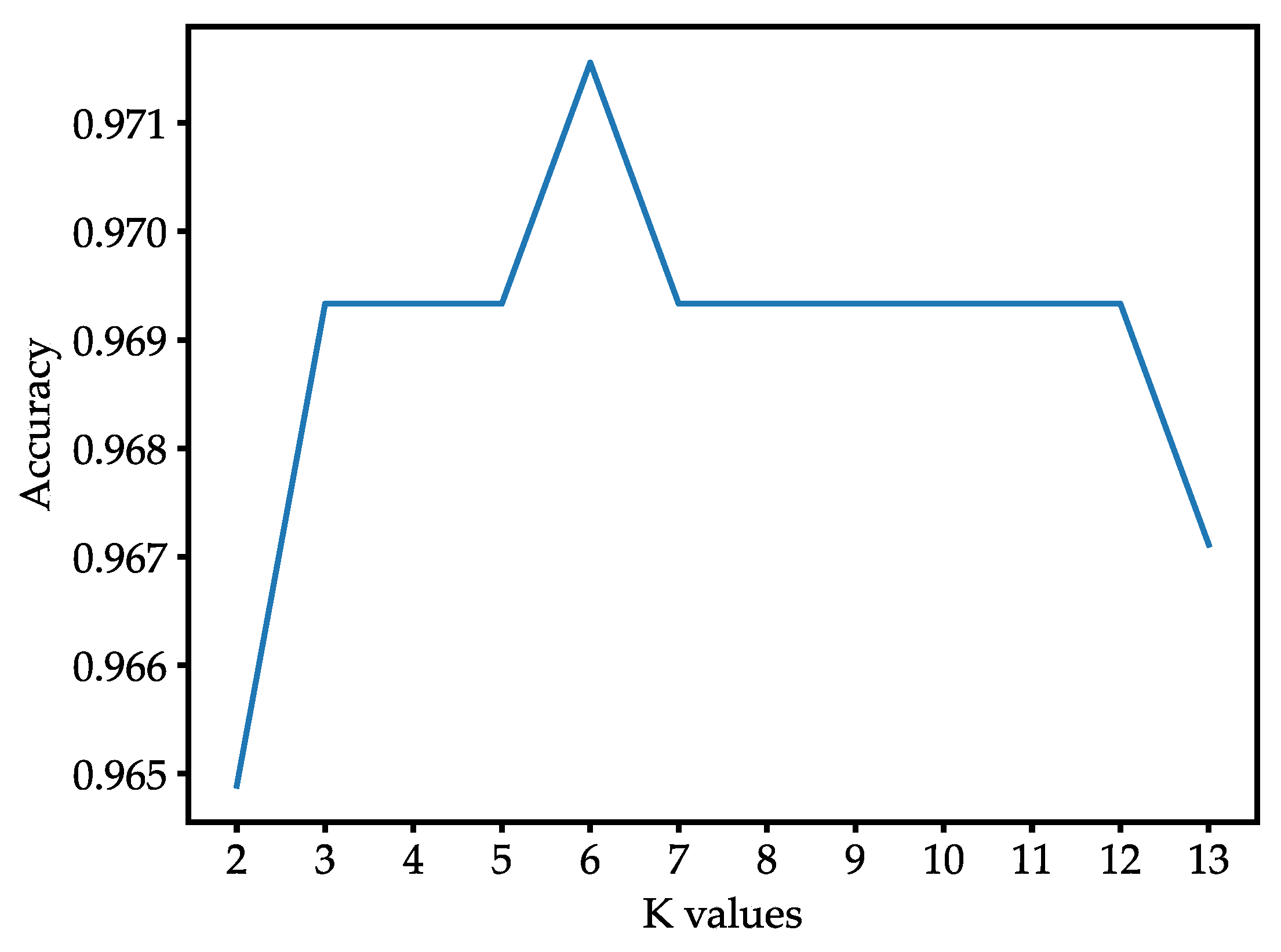
The KNN algorithm is used for classification. The KNN algorithm is a case-based learning method, which starts the classification process only when it receives a prediction request, classifying by finding the K cases in the training set nearest to the new instance [37]. Table 1 shows the process of the KNN algorithm.
Through the KNN algorithm, the motion pattern of each part of the walking process can be recognized. Subsequently, the acceleration data of the walking process are divided into data of taking the stairs and horizontal walking.

3.3. Pedestrian Planar Trajectory Reckoning and Pedestrian Altitude Reckoning

Through pattern recognition, it can be obtained that the time pedestrians pass through some turning points corresponds to that of motion pattern transition. However, in the actual scene, after passing the corner of the corridor, the pedestrian will walk a distance before reaching the stair entrance and get into either the going upstairs or going downstairs pattern, which is the transition part. Therefore, PPTR is proposed to estimate the walking duration of the pedestrian on the transition part and thereby recover the horizontal path.
As mentioned in Section 2.2, the PDR algorithm is performed to recover the horizontal path without the transition part, based on the acceleration data of horizontal walking. And the average speed of the pedestrian on the horizontal path can be calculated. The calculation formula is as follows:
v ¯ = i = 1 n S L i T
where S L i is the step length of each step in the previous horizontal path, and T is the total walking duration. The average speed v ¯ is set as the speed of pedestrians when they walk on the transition part.
The straight distance D from the corner of the corridor to the stair entrance can be obtained from engineering drawings. The walking duration on the transition section is calculated as follows:
τ = D v ¯
where τ is the transition duration. The acceleration data of the first τ seconds of taking the stairs, that is, the acceleration data of the transition part, are extracted and then merged into the data of horizontal walking. The change in the motion pattern occurs at the moment when the pedestrian reaches the stair entrance. Subsequently, the PDR algorithm is performed to recover the horizontal path. Then, the starting point and end point of each horizontal path are obtained.
Based on the acceleration data of taking the stairs, actual terrain information, and starting points and end points produced by PPTR, PAR is performed to recover the stair path.
Considering actual terrain information, the pedestrian will have a short horizontal walking pattern with turns at the half-story height of the building, which will be regarded as turning feature points. Therefore, a one-floor ascending process is decomposed into two parts, and a similar situation is applied to the descending process. The altitude change of the pedestrian walking through the stairs can be obtained as follows:
h = m 2 × H
where m is the number of continuous upstairs or downstairs parts, and H is the story height.
As a simple connection passage between floors, a stair is a strong constraint that only serves to facilitate changes in altitude. And two adjacent horizontal paths are connected by stairs. The end position of a horizontal path is set to ( x , y , 0 ) , where the pedestrian’s motion pattern changes. Since the 2D position does not change after walking through the stairs, the starting position of the adjacent next horizontal path is equal to ( x , y , h ) , where the pedestrian’s motion pattern changes. Note that the change of the motion pattern occurs at the moment when the pedestrian reaches the stair entrance. Therefore, ( x , y , 0 ) and ( x , y , h ) are the positions of the pedestrian entering and leaving the stairs, respectively. The stair path can be recovered by connecting the above two points.
The stair path and horizontal path are combined in chronological order to recover a complete 3D pedestrian path.

3.4. Position Matching-Based Calibration on Stair Path

PMC is proposed to calibrate the stair path. The stair entrance where the pedestrian enters is regarded as the path feature point to form the set M, and the stair entrance of the building is regarded as the terrain feature point to form the set N. The Euclidean distance between all the feature points of the set M and the set N is calculated in turn. The calculation formula is:
d M i , N k = x i x k 2 + y i y k 2 + z i z k 2   ,   i , k = 1,2 , , n
where ( x i , y i , z i ) is the coordinate of the path feature point, and ( x k , y k , z k ) is the coordinate of the terrain feature point.
Having matched the nearest path feature point with the corresponding terrain feature point, the coordinates of the path feature points undergo calibration using those of their respective terrain feature points. This process accomplishes the position calibration. Due to the long Euclidean distance between different stair entrances, the method based on distance matching has a high fault tolerance rate.

3.5. Extended Position Matching-Based Calibration on Horizontal Path

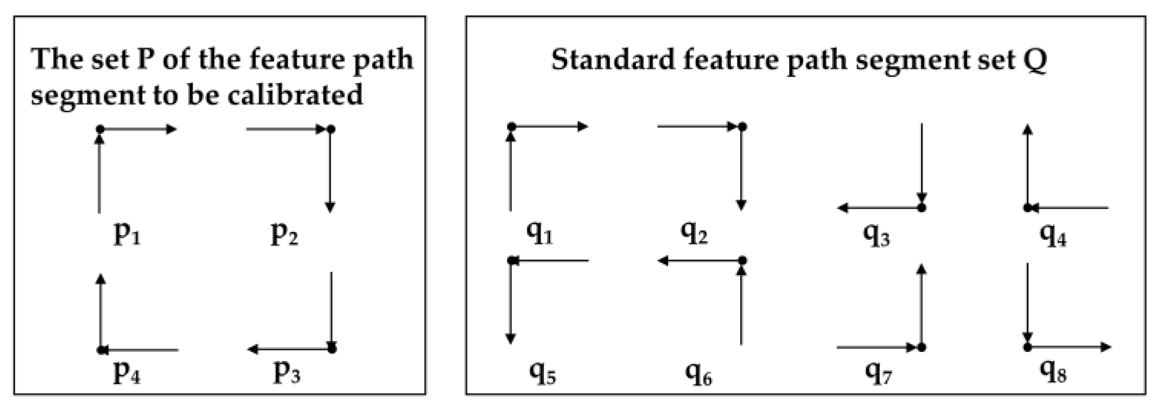
For the horizontal path, due to the close distance between the corner feature points, relying solely on Euclidean distance matching will result in a higher mismatch rate. Therefore, EPMC is proposed to calibrate the horizontal path.
The position where the pedestrian turns is considered to be a path feature point, while the corner of a corridor is deemed to be a terrain feature point. The two-dimensional coordinates of the feature path segment to be calibrated, where the path feature points are located, are extracted to form the set P. The two-dimensional coordinates of the standard feature path segment, where the terrain feature points are located, are extracted to form the set Q as part of the standard path library. The schematic diagram of the path segments is shown in Figure 5.
The abscissa of each point in the feature path segment to be calibrated constitutes the variable P X , and the ordinate constitutes the variable P Y . The abscissa of the points in each standard feature path segment constitutes the variable Q X , and the ordinate constitutes the variable Q Y . The linear correlation coefficients ρ P X Q X and ρ P Y Q Y between the feature path segment to be calibrated and the standard feature path segment are calculated. The calculation formula i:
ρ P X Q X = C o v P X , Q X σ P X σ Q X , ρ P Y Q Y = C o v P Y , Q Y σ P Y σ Q Y
where C o v P X , Q X is the covariance between the variables P X and Q X , and σ P X , σ P Y , σ Q X , σ Q Y are the standard deviations of the variables P X , P Y , Q X , Q Y , respectively. When the linear correlation coefficient is greater than 0.8, it is judged as a very strong positive correlation, meeting the matching conditions. The corresponding feature points of the terrain feature points and the path feature points are matched. Otherwise, no matching is performed.
If the segments in sets P and Q cannot achieve a one-to-one match, the Euclidean distance between the path feature points and the terrain feature points in the remaining path segments is calculated as follows:
d P i , Q k = x i x k 2 + y i y k 2 ,     i , k = 1,2 , , n
where ( x i , y i ) is the coordinate of the path feature point, and ( x k , y k ) is the coordinate of the terrain feature point. The nearest path feature point is matched with the terrain feature point.
After feature point matching, coordinates of the path feature points are calibrated to the coordinates of the matching terrain feature points. Additionally, the step length calibration and yaw calibration can also be performed based on the feature point information at the corner of the corridor.
Concerning step length, when estimating PDR step length, the constructed step length estimation model in Equation (2) may have deviations. Therefore, it is necessary to perform personalized step length estimation for different users through off-line calibration or external information [38]. Since the pedestrian’s motion pattern is relatively stable during horizontal walking, the average step length S L ¯ 
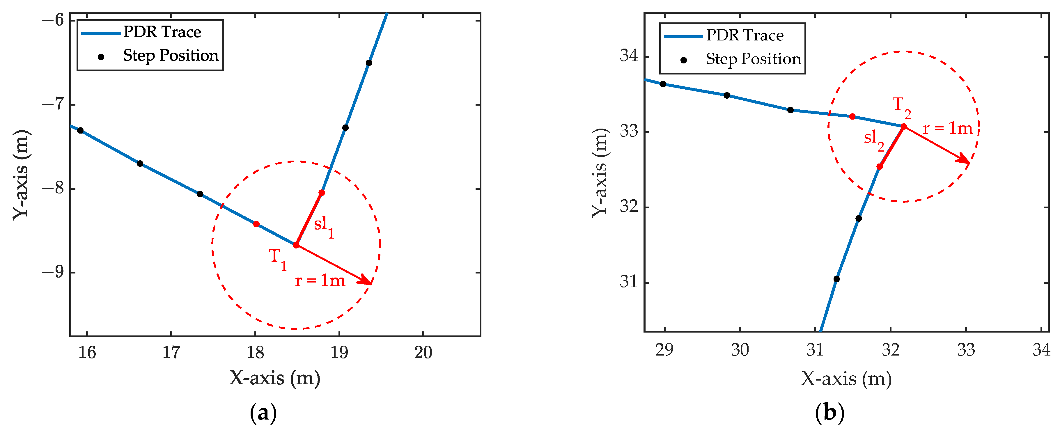
can be used to replace the step length of each step between two adjacent feature points. Considering that the gait speed may change around the corners, the step length before and after the turning point will be affected. When calculating the average step length of pedestrians, the step length affected by the turn is deleted.
Taking the turning point as the center of the circle, a circle with a radius of one meter is made, and the area inside the circle is the turning area. If the step position is in the turning area, it will be deleted. As illustrated in Figure 6, T1 and T2 are two adjacent turning points. Between T1 and T2, their corresponding deleted step lengths are sl1 and sl2, respectively.
The average step length calculation formula is as follows:
S L ¯ = S s l N n
where S is the distance between two adjacent path feature points, as the reference distance of pedestrian walking, and sl is the sum of the deleted step lengths. N is the number of steps between two adjacent path feature points, and n is the number of deleted steps.
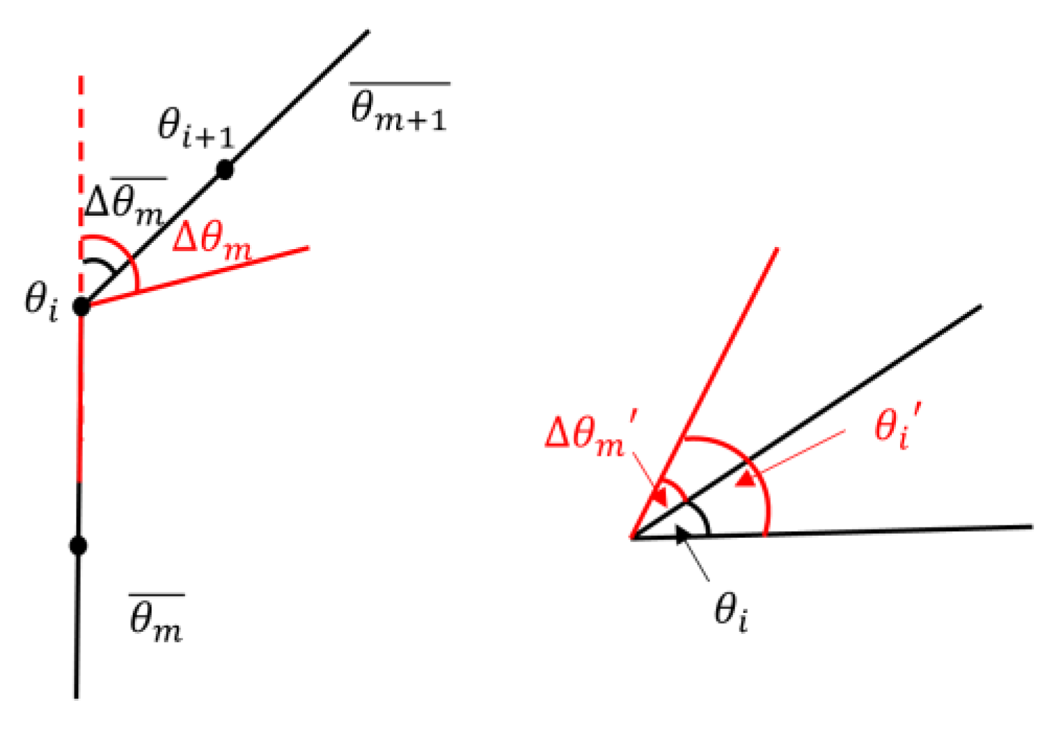
For yaw calibration, the error in the yaw angle will accumulate over time. By matching the feature points, the yaw information corresponding to the terrain feature points can be used as a reliable direction for calibrating the original yaw angle. The calibration process is illustrated in Figure 7.
For the horizontal path divided by the turning point, the difference θ m ¯ between the average yaw angle of the previous horizontal path and the current horizontal path is calculated. And the yaw angle of the current horizontal path is calibrated by the terrain corner angle θ m , corresponding to the turning point. The calculation formula is
θ m = θ m θ m ¯
where θ m is the calibration value of the average yaw angle of the path. The yaw angle of the current path is calibrated to
θ i = θ i + θ m
where θ i represents the yaw angle corresponding to each step of the current path. The calibrated yaw angle is averaged to update the average heading angle θ m + 1 ¯ of the current path. According to the order of the pedestrian passing through the corner of the corridor, the above steps are carried out in turn to complete the yaw calibration.
Finally, the calibrated stair path and horizontal path are combined in chronological order to reconstruct a complete 3D pedestrian path.

4. Experiments

4.1. Motion Pattern Recognition Experiment

As illustrated in Figure 8, the MPU-6050 device produced by InvenSense Company (San Jose, CA, USA) is worn on the tester’s waist, close to the abdomen, and includes an accelerometer and a three-axis gyroscope. The linear acceleration in the vertical direction and yaw angle data are collected at a sampling rate of 50 Hz.
The acceleration data for motion pattern recognition are collected by the tester, who wears inertial sensors and walks freely on the floor and the stairs, respectively. Due to the noise in the data measured by the accelerometer, smoothing filtering is performed to reduce data noise. Then, the IQR of the acceleration data is calculated. Finally, the standard deviation and mean of the IQR are computed as the sample dataset.
The KNN algorithm is performed for motion pattern recognition. The sample dataset is randomly split into training and test sets in a 7:3 ratio, which is subsequently standardized. In order to make the model more accurate and reliable, 10 folds are chosen for cross-validation. Additionally, in the KNN algorithm, a small value of K can be sensitive to outliers, while a large value of K can be affected by sample imbalance. A grid search is conducted for values of K from 2 to 13. As shown in Figure 9, the algorithm achieves the highest accuracy when K is set to 6.
As shown in Figure 10, the training set and the test set after KNN classification are presented. In this feature space composed of two characteristic variables, the feature points of the three motion patterns are widely dispersed, which means significant distinguishability.
KNN classifications are performed on the sample dataset five times, and the obtained motion pattern recognition results are shown in Table 2.
According to the test results, the classification accuracy of the KNN algorithm for the three pedestrian motion patterns is higher than 95%. The comprehensive classification accuracy is 97.03%, which indicates high accuracy for the recognition of motion patterns.

4.2. PDR Calibration Experiment

Experiments were conducted in buildings featuring stairs and corner corridors. The architectural layout of the building is depicted in Figure 11. For the purpose of replicating experiments, two specific sites were chosen:
  • For the horizontal walking path, the pedestrian walked at a constant speed in the following order: starting point → C → B → A → D, covering a walking distance of approximately 150 m.
  • For the three-dimensional walking path, the pedestrian walked at a constant speed, following this order: walking half a circle on the 4th floor → going downstairs → walking half a circle on the 3rd floor → going upstairs → walking back to the starting point on the 4th floor. The total covered walking distance is approximately 145 m.
The collected pedestrian walking three-dimensional path data were used as the test set, while the sample dataset in the motion pattern recognition experiment were used as the training set. The obtained classification results are presented in Table 3. Based on the classification results, the motion patterns of the pedestrian were obtained. The sequence observed was as follows: level ground → descent via stairs (to a lower floor) → level ground → ascent via stairs (to an upper floor) → level ground. This pattern aligns cohesively with the actual scenario.
After MPR and PMC, the inertial navigation positioning calibration results were acquired. The calibrated indoor walking path is shown in Figure 12. Through terrain feature matching, the stair path underwent stair feature point position calibration, while the horizontal walking path underwent calibration of the corridor turning point position, step length, and yaw. The results shown in Figure 12b can verify the feasibility of the proposed method for 3D positioning. The path trajectory after terrain feature matching calibration closely corresponds to the actual walking path.
Figure 13 shows the variation of the positioning error with the walking distance before and after the TFMC. Before the TFMC, the PDR positioning error noticeably accumulates with time. The positioning error is significantly reduced at each feature point by using the TFMC. The improvement in positioning performance is attributed to the combined effect of position calibration, step length calibration, and yaw calibration for the horizontal walking path, along with position calibration for walking on stair paths.
In Figure 14, the cumulative distribution function (CDF) of the positioning error is presented for cases where a single calibration measure is omitted. It shows that the TFMC method keeps 90% of the 2D positioning error within 2.5 m, while 90% of the 3D positioning error is kept within 1 m. For the purpose of measuring the attenuation of the positioning performance by the omission of different calibration measures, in the graph, a horizontal line is made by the point of the curve corresponding to TFMC to intersect with other curves. Based on the distance between the intersection and the starting point, it can be concluded that yaw calibration yields the most influential improvement in positioning performance, while the improvements brought about by position calibration and step length calibration are relatively modest and have similar effects.
Table 4 summarizes the average positioning error, maximum positioning error, and root mean square error (RMSE) after terrain feature matching calibration. The result shows that the TFMC method can significantly reduce the average error of PDR positioning from 6.60 m to 1.37 m, resulting in higher positioning accuracy.

5. Conclusions

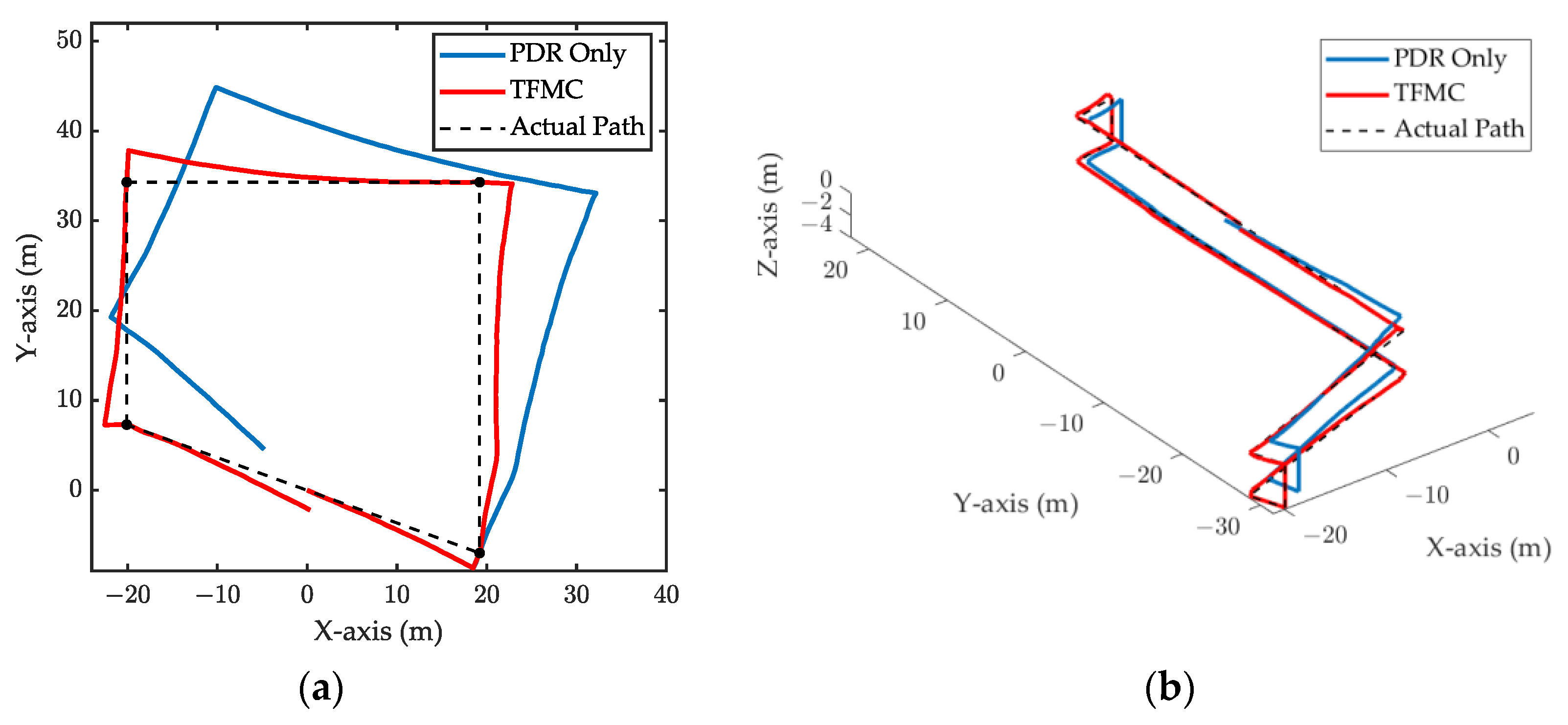
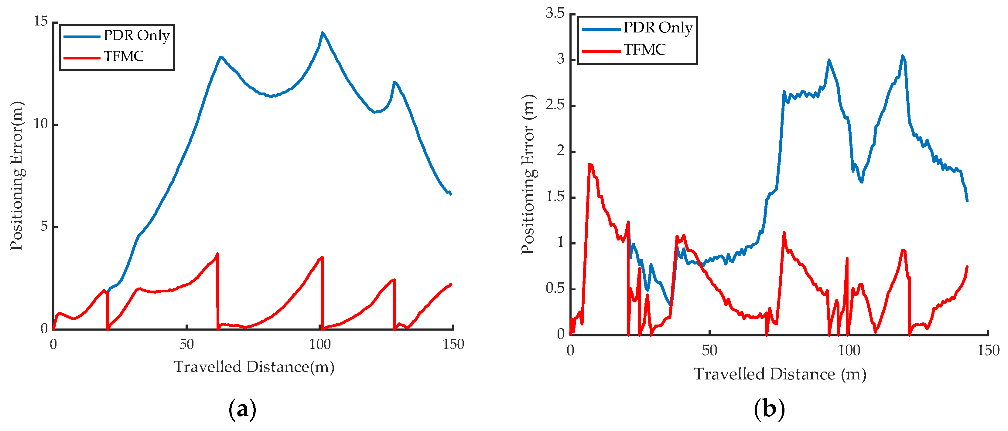
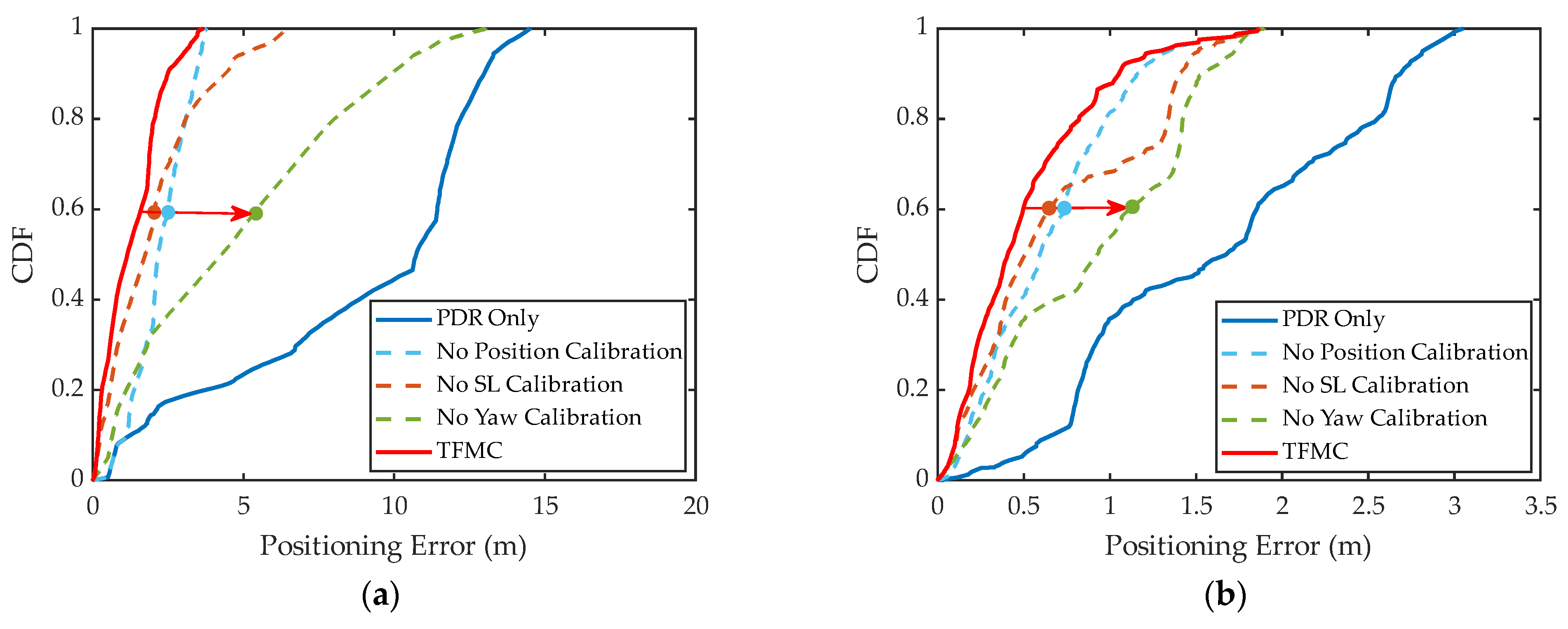
In this work, an indoor 3D positioning algorithm using Terrain Feature Matching Calibration (TFMC) is proposed. The proposed method contains motion pattern recognition and position matching-based calibration. The proposed motion pattern recognition realizes the accurate recognition of pedestrian motion patterns. Based on the motion patterns of pedestrians, the pedestrian 3D walking trajectory can be recovered. The proposed position matching-based calibration can achieve effectively reduce PDR errors to calibrate pedestrian 3D walking trajectory. The experimental results show that the accuracy of motion pattern recognition is over 97%, and the average positioning error decreases from 6.60 m to 1.37 m. Compared with the previous methods that only use IMUs, the proposed method shows an advantage for achieving complete 3D positioning. On this basis, the PDR positioning error is reduced by 79.2%, and accurate 3D positioning is achieved. Due to its sole reliance on inertial sensors without the necessity for additional sensors, the proposed method ensures both convenience and cost-effectiveness, making it a promising choice for indoor positioning in various LBS applications.
In modern buildings, in addition to taking the stairs, a pedestrian can also take the elevator. In the future, the motion pattern of taking the elevator can be included in the motion pattern recognition.

Author Contributions

Conceptualization, X.C. and Y.H.; methodology, X.C.; software, X.C. and Y.X.; validation, Y.X., X.C. and Y.H.; formal analysis, X.C.; investigation, X.C.; resources, X.C.; data curation, Y.H. and X.C.; writing—original draft preparation, Y.X., Z.Z. and X.C.; writing—review and editing, Y.X., Z.Z., Q.W. and X.C.; visualization, X.C.; supervision, Z.C.; project administration, Z.C.; funding acquisition, Z.C. All authors have read and agreed to the published version of the manuscript.

Funding

This research was supported by the Municipal Government of Quzhou under Grant No. 2022D004.

Data Availability Statement

Data will be available on request from the authors.

Conflicts of Interest

The authors declare no conflicts of interest.

References

  1. Zhang, H.; Hu, J.; Zhang, H.; Di, B.; Bian, K.; Han, Z.; Song, L. MetaRadar: Indoor Localization by Reconfigurable Metamaterials. IEEE Trans. Mob. Comput. 2022, 21, 2895–2908. [Google Scholar] [CrossRef]
  2. Bastos, A.S.; Vieira, V.; ApolinArio, A.L. Indoor location systems in emergency scenarios: A Survey. In Proceedings of the Annual Conference on Brazilian Symposium on Information Systems: Information Systems: A Computer Socio-Technical Perspective—Volume 1, Goiania, GO, Brazil, 26–29 May 2015; pp. 251–258. [Google Scholar]
  3. Shipkovenski, G.; Kalushkov, T.; Petkov, E.; Angelov, V. A Beacon-Based Indoor Positioning System for Location Tracking of Patients in Hospital. In Proceedings of the 2nd International Congress on Human-Computer Interaction, Optimization and Robotic Applications (HORA), Ankara, Turkey, 26–27 June 2020; pp. 514–519. [Google Scholar]
  4. Farahsari, P.S.; Farahzadi, A.; Rezazadeh, J.; Bagheri, A. A Survey on Indoor Positioning Systems for IoT-Based Applications. IEEE Internet Things J. 2022, 9, 7680–7699. [Google Scholar] [CrossRef]
  5. Yuan, C.; Lai, J.Z.; Lyu, P.; Shi, P.; Zhao, W.; Huang, K. A Novel Fault-Tolerant Navigation and Positioning Method with Stereo-Camera/Micro Electro Mechanical Systems Inertial Measurement Unit (MEMS-IMU) in Hostile Environment. Micromachines 2018, 9, 626. [Google Scholar] [CrossRef] [PubMed]
  6. Lin, T.Y.; Zhang, Z.Y.; Tian, Z.S.; Zhou, M. Low-Cost BD/MEMS Tightly-Coupled Pedestrian Navigation Algorithm. Micromachines 2016, 7, 91. [Google Scholar] [CrossRef] [PubMed]
  7. Xiao, Z.L.; Wen, H.K.; Markham, A.; Trigoni, N. Robust pedestrian dead reckoning (R-PDR) for arbitrary mobile device placement. In Proceedings of the International Conference on Indoor Positioning and Indoor Navigation (IPIN), Minist Land Infrastructure & Transport, Buan, Republic of Korea, 17–30 October 2014; pp. 187–196. [Google Scholar]
  8. Wang, Y.; Zhao, H. Improved Smartphone-Based Indoor Pedestrian Dead Reckoning Assisted by Visible Light Positioning. IEEE Sens. J. 2019, 19, 2902–2908. [Google Scholar] [CrossRef]
  9. He, K.; Zhang, Y.Y.; Zhu, Y.P.; Xia, W.W.; Jia, Z.Y.; Shen, L.F. A Hybrid Indoor Positioning System Based on UWB and Inertial Navigation. In Proceedings of the 7th IEEE International Conference on Wireless Communications and Signal Processing (WCSP), Nanjing, China, 15–17 October 2015. [Google Scholar]
  10. Du, X.Q.; Liao, X.W.; Liu, M.M.; Gao, Z.Z. CRCLoc: A Crowdsourcing-Based Radio Map Construction Method for WiFi Fingerprinting Localization. IEEE Internet Things J. 2021, 9, 12364–12377. [Google Scholar] [CrossRef]
  11. Koo, B.; Lee, S.; Lee, M.; Lee, D.; Lee, S.; Kim, S. PDR/Fingerprinting Fusion Indoor Location Tracking Using RSS Recovery and Clustering. In Proceedings of the International Conference on Indoor Positioning and Indoor Navigation (IPIN), Minist Land Infrastructure & Transport, Buan, Republic of Korea, 27–30 October 2014; pp. 699–704. [Google Scholar]
  12. Wang, Q.; Luo, H.; Xiong, H.; Men, A.; Zhao, F.; Xia, M.; Ou, C. Pedestrian Dead Reckoning Based on Walking Pattern Recognition and Online Magnetic Fingerprint Trajectory Calibration. IEEE Internet Things J. 2021, 8, 2011–2026. [Google Scholar] [CrossRef]
  13. Zhao, T.Y.; Ahamed, M.J. Pseudo-Zero Velocity Re-Detection Double Threshold Zero-Velocity Update (ZUPT) for Inertial Sensor-Based Pedestrian Navigation. IEEE Sens. J. 2021, 21, 13772–13785. [Google Scholar] [CrossRef]
  14. Wei, R.; Xu, H.; Yang, M.; Yu, X.; Xiao, Z.; Yan, B. Real-Time Pedestrian Tracking Terminal Based on Adaptive Zero Velocity Update. Sensors 2021, 21, 3808. [Google Scholar] [CrossRef]
  15. Yu, N.; Li, Y.; Ma, X.; Wu, Y.; Feng, R. Comparison of Pedestrian Tracking Methods Based on Foot- and Waist-Mounted Inertial Sensors and Handheld Smartphones. IEEE Sens. J. 2019, 19, 8160–8173. [Google Scholar] [CrossRef]
  16. Liu, Z.X.; Won, C.H. Knee and Waist Attached Gyroscopes for Personal Navigation: Comparison of Knee, Waist and Foot Attached Inertial Sensors. In Proceedings of the Position Location and Navigation Symposium (PLANS), Palm Springs, CA, USA, 4–6 May 2010; pp. 1042–1048. [Google Scholar]
  17. Li, H.; Liu, Y.; Zhang, L.Q.; Wang, H. Magnetic Matching-Aided Indoor Localization System Based on a Waist-Mounted Self-Contained Sensor Array. J. Sens. 2022, 2022, 1710907. [Google Scholar] [CrossRef]
  18. Shi, J.; Ren, M.; Wang, P.; Meng, J. Research on PF-SLAM Indoor Pedestrian Localization Algorithm Based on Feature Point Map. Micromachines 2018, 9, 267. [Google Scholar] [CrossRef] [PubMed]
  19. Zizzo, G.; Ren, L. Position Tracking During Human Walking Using an Integrated Wearable Sensing System. Sensors 2017, 17, 2866. [Google Scholar] [CrossRef] [PubMed]
  20. Gu, F.; Valaee, S.; Khoshelham, K.; Shang, J.; Zhang, R. Landmark Graph-Based Indoor Localization. IEEE Internet Things J. 2020, 7, 8343–8355. [Google Scholar] [CrossRef]
  21. Ghaoui, M.A.; Vincke, B.; Reynaud, R. Human Motion Likelihood Representation Map-Aided PDR Particle Filter. IEEE Sens. J. 2023, 23, 484–494. [Google Scholar] [CrossRef]
  22. Yang, W.; Xiu, C.D.; Zhang, J.M.; Yang, D.K. A Novel 3D Pedestrian Navigation Method for a Multiple Sensors-Based Foot-Mounted Inertial System. Sensors 2017, 17, 2695. [Google Scholar] [CrossRef]
  23. Zhao, Y.L.; Liang, J.Q.; Sha, X.P.; Yu, J.N.; Duan, H.J.; Shi, G.Y.; Li, W.J. Estimation of Pedestrian Altitude Inside a Multi-Story Building Using an Integrated Micro-IMU and Barometer Device. IEEE Access 2019, 7, 84680–84689. [Google Scholar] [CrossRef]
  24. Nam, L.S. Pedestrian Navigation System in Mountainous non-GPS Environments. J. Inf. Commun. Converg. Eng. 2021, 19, 188–197. [Google Scholar] [CrossRef]
  25. Xie, D.P.; Jiang, J.G.; Yan, P.H.; Wu, J.J.; Li, Y.Y.; Yu, Z.Y. A Novel Three-Dimensional Positioning Method for Foot-Mounted Pedestrian Navigation System Using Low-Cost Inertial Sensor. Electronics 2023, 12, 845. [Google Scholar] [CrossRef]
  26. Wang, X.; Jiang, M.X.; Guo, Z.W.; Hu, N.J.; Sun, Z.W.; Liu, J. An Indoor Positioning Method for Smartphones Using Landmarks and PDR. Sensors 2016, 16, 2135. [Google Scholar] [CrossRef]
  27. Xia, M.; Shi, C. Autonomous Pedestrian Altitude Estimation Inside a Multi-Story Building Assisted by Motion Recognition. IEEE Access 2020, 8, 104718–104727. [Google Scholar] [CrossRef]
  28. Elhoushi, M.; Georgy, J.; Noureldin, A.; Korenberg, M.J. Motion Mode Recognition for Indoor Pedestrian Navigation Using Portable Devices. IEEE Trans. Instrum. Meas. 2016, 65, 208–221. [Google Scholar] [CrossRef]
  29. Fang, Q.; Xu, X.; Wang, X.T.; Zeng, Y.J. Target-driven visual navigation in indoor scenes using reinforcement learning and imitation learning. CAAI Trans. Intell. Technol. 2022, 7, 167–176. [Google Scholar] [CrossRef]
  30. Alaoui, F.T.; Renaudin, V.; Betaille, D. Points of Interest Detection for Map-Aided PDR in Combined Outdoor-Indoor spaces. In Proceedings of the 8th International Conference on Indoor Positioning and Indoor Navigation (IPIN), Sapporo, Japan, 18–21 September 2017. [Google Scholar]
  31. Wang, G.J.; Li, Q.Q.; Wang, L.; Wang, W.; Wu, M.Q.; Liu, T. Impact of Sliding Window Length in Indoor Human Motion Modes and Pose Pattern Recognition Based on Smartphone Sensors. Sensors 2018, 18, 1965. [Google Scholar] [CrossRef] [PubMed]
  32. Xia, H.; Zuo, J.B.; Liu, S.; Qiao, Y.Y. Indoor Localization on Smartphones Using Built-In Sensors and Map Constraints. IEEE Trans. Instrum. Meas. 2019, 68, 1189–1198. [Google Scholar] [CrossRef]
  33. Khedr, M.; El-Sheimy, N. A Smartphone Step Counter Using IMU and Magnetometer for Navigation and Health Monitoring Applications. Sensors 2017, 17, 2573. [Google Scholar] [CrossRef] [PubMed]
  34. Weinberg, H. Using the ADXL202 in Pedometer and Personal Navigation Applications; AN-602 Application Note; One Technology Way: Norwood, MA, USA, 2002; pp. 1–6. [Google Scholar]
  35. Jang, B.; Kim, H.; Kim, J.W. Survey of Landmark-based Indoor Positioning Technologies. Inf. Fusion 2023, 89, 166–188. [Google Scholar] [CrossRef]
  36. Xue, Y.; Jin, L.W. Discrimination between Upstairs and Downstairs Based on Accelerometer. IEICE Trans. Inf. Syst. 2011, E94D, 1173–1177. [Google Scholar] [CrossRef]
  37. Susi, M.; Borio, D.; Lachapelle, G. Accelerometer signal features and classification algorithms for positioning applications. In Proceedings of the Institute of Navigation—International Technical Meeting 2011, San Diego, CA, USA, 24–26 January 2011; pp. 158–169. [Google Scholar]
  38. He, S.N.; Chan, S.H.G. Wi-Fi Fingerprint-Based Indoor Positioning: Recent Advances and Comparisons. IEEE Commun. Surv. Tutor. 2016, 18, 466–490. [Google Scholar] [CrossRef]
Figure 1. TFMC method flow.
Electronics 13 01468 g001
Figure 2. The sub-IQR after data division.
Electronics 13 01468 g002
Figure 3. Divided IQR cumulative probability distribution.
Electronics 13 01468 g003
Figure 4. Comparison of mean and standard deviation of IQR under different motion patterns; (a) Mean; (b) Standard deviation.
Electronics 13 01468 g004
Figure 5. A schematic diagram of the set of feature path segments to be calibrated and standard feature path segments.
Electronics 13 01468 g005
Figure 6. Step length deletion: (a) Turning point 1; (b) Turning point 2.
Electronics 13 01468 g006
Figure 7. Yaw angle calibration diagram.
Electronics 13 01468 g007
Figure 8. Experimental hardware.
Electronics 13 01468 g008
Figure 9. Classification accuracy under different values of K.
Electronics 13 01468 g009
Figure 10. KNN classifier results. ‘U’ represents going upstairs, ‘H’ represents walking horizontally and ‘D’ represents going downstairs.
Electronics 13 01468 g010
Figure 11. Schematic diagram of building plane structure.
Electronics 13 01468 g011
Figure 12. The path diagram before and after the TFMC; (a) Calibration of the corner feature points of the horizontal corridor; (b) Calibration of stair entrance and corridor corner feature points of the three-dimensional path.
Electronics 13 01468 g012
Figure 13. The comparison map of positioning error before and after the TFMC; (a) Calibration of the corner feature points of the horizontal corridor; (b) Calibration of stair entrance and corridor corner feature points of the three-dimensional path.
Electronics 13 01468 g013
Figure 14. The influence of position calibration, SL calibration and yaw calibration on positioning performance; (a) Horizontal path; (b) Three-dimensional path.
Electronics 13 01468 g014
Table 1. Process of KNN algorithm.
Input: Dataset   T = { x 1 , y 1 , x 2 , y 2 , , x n , y n } ,   x i   represents   the   feature   vector   of   the   instance ,   and   y i = { c 1 , c 2 , , c k } represents the category of the instance.
Steps:
  • Choose parameter K.
  • Calculate the Euclidean distance between the unknown instance and all known instances.
  • Select the nearest K known instances.
  • According to the majority voting rule, classify the unknown instance as the category most common among the K nearest samples.
Output: The   category   y   to   which   the   instance   x belongs.
Table 2. Test set data pattern classification results.
Motion PatternPattern Classification Results
UpstairsHorizontal WalkingDownstairsAccuracy
Upstairs43012097.29%
Horizontal walking23597395.83%
Downstairs0744398.44%
Table 3. Walking data classification results. ‘U’ represents going upstairs, ‘H’ represents walking horizontally, and ‘D’ represents going downstairs.
Walking DataL1L2L3L4L5L6L7L8L9
Classification resultHDDHHUUHH
Table 4. Comparison of positioning errors after the TFMC.
Positioning ErrorPDR OnlyTFMC
Average error (m)6.601.37
Maximum error (m)12.153.00
RMSE (m)7.451.58
Disclaimer/Publisher’s Note: The statements, opinions and data contained in all publications are solely those of the individual author(s) and contributor(s) and not of MDPI and/or the editor(s). MDPI and/or the editor(s) disclaim responsibility for any injury to people or property resulting from any ideas, methods, instructions or products referred to in the content.

