Article

Robust Direct Power Control of Three-Phase PWM Rectifier with Mismatched Disturbances

School of Electrical Engineering, Shaanxi University of Technology, Hanzhong 723001, China
*
Author to whom correspondence should be addressed.
Electronics 2024, 13(8), 1476; https://doi.org/10.3390/electronics13081476
Submission received: 23 March 2024 / Revised: 10 April 2024 / Accepted: 11 April 2024 / Published: 13 April 2024
(This article belongs to the Section Power Electronics)

Abstract

:
To effectively eliminate the impacts of both matched and mismatched power disturbances in a three-phase PWM rectifier, this paper proposes a robust direct power control (RDPC) method with a single-loop control structure. Firstly, a nonlinear power model of the three-phase PWM rectifier is established. Then, using the exact feedback linearization method, a linearized power model including matched and mismatched power disturbances is derived and achieves the decoupling of active and reactive power. Secondly, to regulate the DC bus voltage, a sliding-mode controller (SMC) combined with a nonlinear disturbance observer (NDO) is proposed. The proposed SMC combined with an NDO (SMC + NDO) method features a single-loop control structure, which enables a faster response and simpler structure compared to the dual-loop DPC method. By incorporating estimated mismatched power disturbance into the sliding-mode surface, it overcomes the SMC’s defect in incompletely suppressing mismatched disturbances and enables the simultaneous regulation of voltage and active power. Additionally, it effectively reduces sliding-mode chattering. To regulate reactive power, a sliding-mode controller based on the exponential convergence law is designed to suppress matched reactive power disturbances. Finally, the simulation and experimental comparative results demonstrate that the proposed controller exhibits stronger robustness against matched and mismatched power disturbances, as well as a better performance under the constant power load (CPL).

1. Introduction

As commonly used powerful electronic devices, three-phase PWM rectifiers are extensively employed in DC microgrids (MG) [1,2]. Figure 1 illustrates the three-phase PWM rectifier’s function as a crucial interface between the power grid and the DC MG. Its primary function is to maintain a constant DC bus voltage under resistive and power load conditions [2]. However, the CPL possesses a negative impedance property, which imposes stricter requirements on the control performance of the three-phase PWM rectifier [3]. Therefore, designing controllers for three-phase PWM rectifiers has become a research hotspot in the field of MG. Currently, control strategies for three-phase PWM rectifiers are mainly classified into voltage-oriented control (VOC) and direct power control (DPC). VOC can achieve a fast dynamic response and high-precision steady-state performance. However, its dynamic response is susceptible to the performance of the internal current loop and the phase-locked loop [4,5]. The DPC method takes the active and reactive power on the grid side as the object to be controlled and effectively overcomes this problem by eliminating the need for both the phase-locked loop and the current loop [6]. Additionally, compared to the VOC, the DPC exhibits a higher power factor, lower total harmonic distortion (THD), better dynamic response, and stronger robustness. As a result, DPC has attracted widespread attention from scholars [7,8,9].
In recent years, scholars have proposed several novel methods to enhance the performance of the DPC. In [10], a proportional integral (PI) based on the virtual flux DPC (VF-DPC) is proposed. However, it exhibits a slow dynamic response and poor anti-disturbance ability. Reference [11] proposes the voltage-modulated DPC. This approach converts a linear time-varying system of the rectifier into a linear time-invariant one and offers a simple way to design a power controller. Both dynamic response and steady-state performance are improved. Predictive control is considered a preferred solution for improving system dynamic performance [12]. Reference [13] proposes a robust deadbeat DPC method for three-phase unbalanced grids. The aforementioned DPC approaches are classed as linear controls in control theory. It is well known that linear control is commonly designed based on a linearized model near the steady-state operating point. However, because of the three-phase PWM rectifier’s nonlinearity, linear control is inadequate in providing optimal control over the whole working range [14]. Nonlinear control approaches do not need system linearization and instead use a nonlinear model to design the controller, resulting in global stability and optimum control across a large working range [15]. Therefore, research on nonlinear control methods for three-phase PWM rectifiers has become a popular topic in power electronics. Scholars have recently proposed various nonlinear DPC methods for rectifiers, including feedback linearization control [16], backstepping sliding-mode control [17], adaptive control [18], and sliding-mode control (SMC) [19].
Currently, DPC based on SMC has become an important research hotspot in the field of rectifier control due to its simple structure, fast response, and strong robustness to system disturbances. In [20], traditional sliding-mode control (TSMC) is used in the outer loop design to enhance anti-disturbance capability with loads. Nevertheless, TSMC requires a sufficiently large switching gain to suppress load disturbances, which leads to severe sliding-mode chattering. To enhance resistance to disturbance and reduce sliding-mode chattering, an outer loop controller is designed using TSMC and a current observer in [21]. The power inner loop in [20,21] is designed using the finite control set model predictive control (FCS-MPC) and PI decoupling control, respectively. However, both FCS-MPC and PI control lack robustness against system parameter uncertainty and external disturbances. In [22], an extended state observer (ESO) and second-order sliding-mode control (SOSM) are employed for the inner and outer loops, respectively. The experimental results show excellent tracking performance and strong robustness against resistive load variations. One article [23] proposes an improved DPC strategy based on the SMC with dual-loop for the Vienna-type rectifier. The inner power loop uses a SMC-DPC controller to directly regulate voltage without transforming to a synchronous rotating coordinate reference frame or tracking phase angle of the grid voltage. The control structures described in [20,21,22,23] are dual-loop control structures. However, to avoid excessive overshoot and ringing, the bandwidth of dual-loop control must be limited. Additionally, the small time constant of the inner loop also affects the system’s dynamic performance [24].
Single-loop control has several advantages over dual-loop control, including fewer parameters and faster dynamic responses due to the absence of an inner loop. Other works [24,25,26] proposed a single-loop control structure of permanent magnet synchronous motor-speed-control method, which realized the simultaneous control of speed and current. Another paper [27] designed a robust single-loop control strategy, which significantly improved the dynamic response speed and robustness. Another study [24,25,26,27] demonstrated the feasibility and effectiveness of a single-loop control structure in power electronic systems. However, there is very little research on direct power control for three-phase PWM rectifiers with a single-loop structure. Reference [17] proposes a backstepping direct power control (BDPC) method. To suppress large load disturbances, this method employs a high switching gain, which increases sliding-mode chattering. Additionally, the BDPC is based on positive impedance load modeling, and therefore cannot be theoretically used for constant power loads (CPLs) with nonlinear negative impedance characteristics. Furthermore, prior knowledge of the load is required for the BDPC.
In practical systems, disturbances are often classified as matched or mismatched [28]. The control problem with mismatched disturbances is considerably more challenging than that with matched disturbances [29]. According to the rectifier power model and the definition of matched/mismatched disturbances, it can be seen that three-phase PWM rectifiers have both mismatched disturbances (load power disturbances) and matched disturbances (parameter uncertainty, unmodeled dynamics, etc.). Currently, these have been reports of control issues with mismatched disturbances in boost converters [30], buck converters [31], vehicles [32], etc. However, to the best of our knowledge, the control problem for the mismatched power disturbances of rectifiers has not been reported.
For the above reasons, this paper proposes a robust direct power control (RDPC) method for three-phase PWM rectifiers under matched and mismatched disturbances, based on the feedback linearization theory, SMC, and NDO. The proposed RDPC is a single-loop structure that requires only one controller to regulate both DC bus voltage and active power simultaneously, which simplifies effectively the control structure. In the process of exact feedback linearization, the established nonlinear power model is more suitable for engineering practice, as it takes into account lumped disturbances and unmodeled dynamics. This model also decouples active and reactive power. The Lyapunov theory is then used to design the NDO, estimating mismatched power disturbances and the sliding-mode controller, so the global stability is effectively guaranteed. The RDPC not only avoids the impact of matched and mismatched disturbances on control performance but also effectively reduces sliding-mode chattering. Additionally, the RDPC does not require load-current measurement or prior knowledge of disturbance upper bounds. The correctness and effectiveness of the RDPC have been confirmed through simulation and experimental comparison.

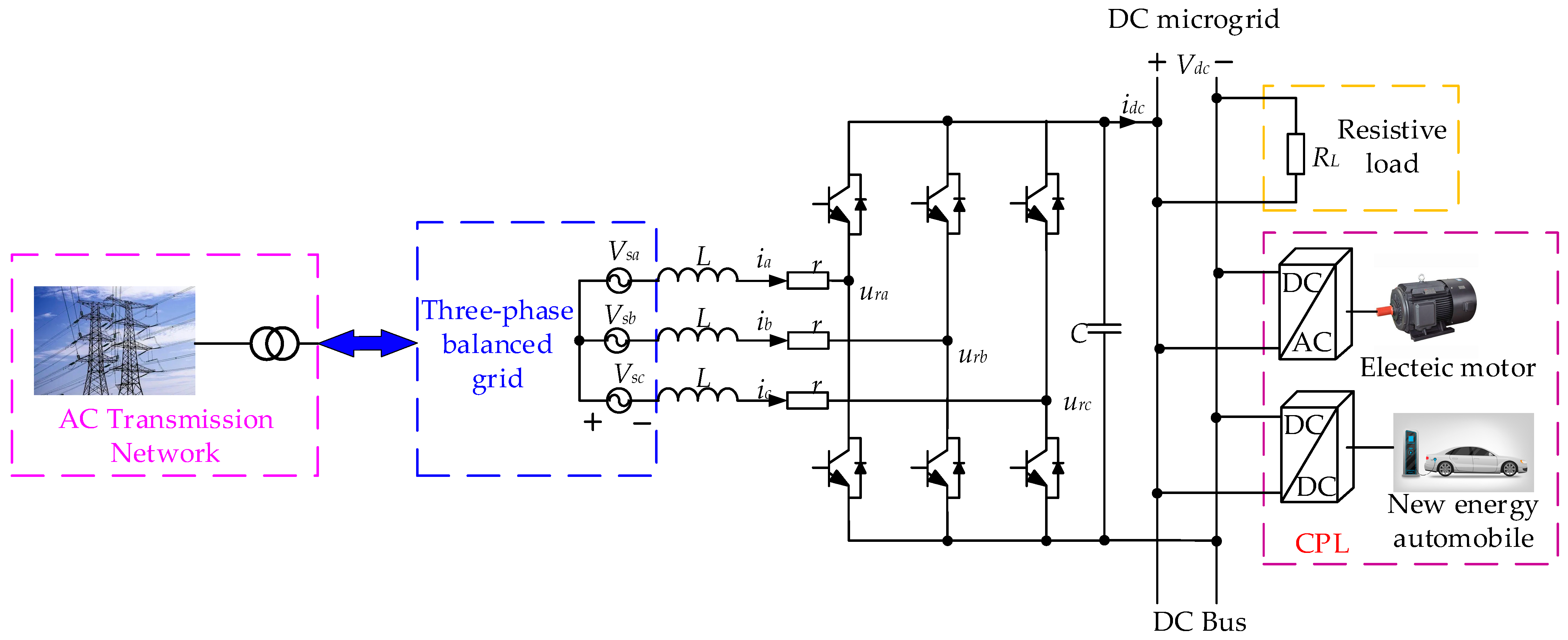
2. Nonlinear Power Model of Three-Phase PWM Rectifier

The circuit of a three-phase PWM rectifier in the DC MG is depicted in Figure 1. The AC-side of the rectifier links to the AC transmission network, and it can be considered an ideal three-phase power supply. In Figure 1, Vsa, Vsb, and Vsc are three-phase grid voltages, Vdc is the DC bus voltage, ia, ib, and ic are three-phase grid currents, L is the filtering inductance, r is the equivalent resistance, and C is the output filtering capacitance. Within the DC MG, the loads linked to the DC bus are mainly linear loads (resistive loads) and CPLs (power converters, new energy automobiles, motors, etc.).

2.1. AC-Side Power Model

From Figure 1, the AC-side power model can be expressed as follows [21].
d P d t = r L P ω Q 3 2 L u P + 3 2 L V s 2 d Q d t = r L Q + ω P + 3 2 L u Q
where
P = 3 2 ( V s α i α + V s β i β ) Q = 3 2 ( V s β i α V s α i β )
u P = ( V s α u r α + V s β u r β ) u Q = ( V s β u r α + V s α u r β )
where P and Q are instantaneous active and reactive power, up and uq represent the control inputs of active and reactive power, Vsαβ, iαβ, and urαβ represent the grid-side voltage, grid-side current, and control inputs in the αβ coordinate system, Vs represents the grid-side voltage amplitude, and ω represents the grid-side voltage angular frequency.
Since the grid-side filtering inductance parameter L and equivalent resistance r may vary within a certain range during rectifier operation [33,34], and there exits unmodeled dynamics in the modeling process, the AC-side power model can be rewritten as
d P d t = r 0 L 0 P ω Q 3 2 L 0 u P + 3 2 L 0 V s 2 + ε 1 d Q d t = r 0 L 0 Q + ω P + 3 2 L 0 u Q + ε 2
where
ε 1 = L 0 Δ r r 0 Δ L L L 0 P + 3 Δ L 2 L L 0 u P 3 Δ L 2 L L 0 V s 2 + ω 1 ε 2 = L 0 Δ r r 0 Δ L L L 0 Q 3 Δ L 2 L L 0 u Q + ω 2
where ε1 and ε2 are the lumped disturbances. L = L0 + ΔL, L0 represents model inductance, ΔL represents deviation between actual inductance L and model inductance L0. r = r0 + Δr, r0 represents model resistance, and Δr represents deviation between actual resistance r and model resistance r0. ω1 and ω2 are unmodeled dynamics. From the physical properties of the inductors, we know that ΔL and Δr are bounded, and ω1 and ω2 are also bounded. To ensure protection and avoid over-modulation, P, Q, up, and uq must be bounded. In addition, Vs is provided by the power grid. According to (5), ε1 and ε2 must be bounded, namely, ε 1 < A 1 , ε 2 < A 2 . Here, A1 and A2 are the upper bounds of ε1 and ε2, respectively, and A1 > 0 and A2 > 0.

2.2. DC-Side Power Model

According to Figure 1, the DC-side power model can be obtained as [21].
d ( V d c 2 ) d t = 2 C P 2 C P L
where PL represents the power consumed by the load. Since capacitance C may vary within a certain range during rectifier operation, and there exists certain unmodeled dynamics in the modeling process [33,34], Equation (6) can be rewritten as
d ( V d c 2 ) d t = 2 C 0 P 2 C 0 P L + ε 3
where
ε 3 = 2 Δ C C C 0 P + 2 Δ C C C 0 P L + ω 3
where ω3 is the unmodeled dynamics of the DC-side power model. C = C0 + ΔC, C0 represents model capacitance, and ΔC represents the deviation between actual capacitance C and model capacitance C0. From the physical properties of the capacitor, it is known that ΔC and ω3 are bounded. To ensure protection, P and PL must be bounded. According to (8), ε3 is bounded, namely, ε 3 < A 3 . Here, A3 is the upper bound of ε3 and A3 > 0.

2.3. Nonlinear Power Model of Three-Phase PWM Rectifier

From (4) and (7), the nonlinear power model of the three-phase PWM rectifier can be expressed as
d ( V d c 2 ) d t = 2 C 0 P 2 C 0 P L + ε 3 d P d t = r 0 L 0 P ω Q 3 2 L 0 u P + 3 2 L 0 V s 2 + ε 1 d Q d t = r 0 L 0 Q + ω P + 3 2 L 0 u Q + ε 2
Equation (9) shows that the three-phase PWM rectifier is a multi-input–multi-output (MIMO) nonlinear system with multiple disturbances and a strong coupling between active power and reactive power. Therefore, this paper employs the exact feedback linearization to achieve global linearization in the following section.

3. Exact Feedback Linearized Power Model with Matched and Mismatched Disturbances

3.1. AC-Side Exact Feedback Linearized Power Model

Theorem 1. 
Conditions for exact linearization of nonlinear systems [14]
1.
Near the equilibrium point, the rank of the matrix
a d f 0 g 1 ( x ) a d f 0 g n ( x ) a d f n 1 g 1 ( x ) a d f n 1 g n ( x )  is always equal to the dimension of the state variable.
2.
The set of vector fields
D = a d f 0 g 1 ( x ) a d f 0 g n ( x ) a d f n 1 g 1 ( x ) a d f n 1 g n ( x )  is involutive within the domain.
Following (9), this article establishes an affine nonlinear model of the three-phase PWM rectifier, as shown in (10).
x ˙ = f ( x ) + g 1 ( x ) u P + g 2 ( x ) u Q + g 3 ( x ) ε 1 + g 4 ( x ) ε 2 y 1 = h 1 ( x ) y 2 = h 2 ( x )
where f ( x ) = 3 2 L 0 V s 2 ω x 2 r 0 L 0 x 1 ω x 1 r 0 L 0 x 2 , g 1 ( x ) = 3 2 L 0 0 , g 2 ( x ) = 0 3 2 L 0 , g 3 ( x ) = 1 0 , g 4 ( x ) = 0 1 . The state variables are x = x 1 x 2 = P Q , the control input variables are u = u P u Q , the disturbance variables are ε = ε 1 ε 2 , and the output variable are y = y 1 y 2 = h 1 ( x ) h 2 ( x ) = x 1 x 2 .
Firstly, verify whether the power model without disturbances satisfies the exact feedback linearization condition. From (10), it can be concluded that
x ˙ = f ( x ) + g 1 ( x ) u P + g 2 ( x ) u Q y 1 = h 1 ( x ) y 2 = h 2 ( x )
From (11), the Lie bracket can be found to be
a d f g 1 ( x ) = g 1 ( x ) x f ( x ) f ( x ) x g 1 ( x ) = 3 r 2 L 0 2 3 ω 2 L 0 a d f g 2 ( x ) = g 2 ( x ) x f ( x ) f ( x ) x g 2 ( x ) = 3 ω 2 L 0 3 r 2 L 0 2
From (12), we can obtain matrix A, following as
A = g 1 ( x ) g 2 ( x ) a d f g 1 ( x ) a d f g 2 ( x ) = 3 2 L 0 0 3 r 0 2 L 0 2 3 ω 2 L 0 0 3 2 L 0 3 ω 2 L 0 3 r 0 2 L 0 2
The rank of A is two, which satisfies condition 1 of Theorem 1 as it is equal to the dimension of the state variable. Moreover, condition 2 of Theorem 1 is satisfied as the dimension is two and the vector field D is involutive. Therefore, the system (10) can achieve an exact linearization through state feedback. The exact linearization process is as follows.
Firstly, calculate the relational degree of the system. According to the definition of relational degree, it can be expressed as
L g 1 L f 0 h 1 ( x ) L g 2 L f 0 h 1 ( x ) L g 1 L f 0 h 2 ( x ) L g 2 L f 0 h 2 ( x ) = 3 2 L 0 0 0 3 2 L 0
From (14), the total relational degree of the system is r = r1 + r2 = 2, which is equal to the system’s dimension. Therefore, we choose the diffeomorphism mapping Φ(x) as
ϕ ( x ) = z 1 z 2 = L f r 1 1 h 1 ( x ) L f r 2 1 h 2 ( x ) = P Q
Diffeomorphism mapping is applied to the disturbance ε1 and ε2, and the mapped disturbance terms φ1, φ2 are
φ = φ 1 φ 2 = L g 3 L f r 1 1 h 1 ( x ) ε 1 + L g 4 L f r 1 1 h 1 ( x ) ε 2 L g 3 L f r 2 1 h 2 ( x ) ε 1 + L g 4 L f r 2 1 h 2 ( x ) ε 2 = ε 1 ε 2
Secondly, choose the state feedback control law as
v = v P v Q = b ( x ) + E ( x ) u P u Q
where vp and vq represent the state feedback control input variables of P and Q, respectively. b ( x ) = L f r 1 h 1 ( x ) L f r 2 h 2 ( x ) , E ( x ) = L g 1 L f r 1 1 h 1 ( x ) L g 2 L f r 1 1 h 1 ( x ) L g 1 L f r 2 1 h 2 ( x ) L g 2 L f r 2 1 h 2 ( x ) .
Finally, by combining Equations (10) and (15)–(17), the Brunovsky standard form of the AC-side exact-feedback linearized power model can be obtained [14]:
z ˙ 1 = v P + φ 1 z ˙ 2 = v Q + φ 2 y 1 = z 1 y 2 = z 2
P and Q in (18) are decoupled. The linearization process takes into account parameter uncertainty and disturbances; thus, (18) is more suitable for practical engineering.

3.2. Power Model with Matched and Mismatched Disturbances

Based on (9), (15), and (18), the power model can be obtained as
d ( V d c 2 ) d t = 2 C 0 P 2 C 0 P L + ε 3 d P d t = v P + φ 1 d Q d t = v Q + φ 2
The load power PL is usually unknown. If PL and ε3 are treated as lumped disturbances d1(t), then
d ( V d c 2 ) d t = 2 C 0 P + d 1 ( t ) d P d t = v P + d 2 ( t ) d Q d t = v Q + d 3 ( t )
where d 1 ( t ) = 2 C 0 P L + ε 3 , d 2 ( t ) = φ 1 , and d 3 ( t ) = φ 2 . Matched disturbances and control inputs act on the same channel, while mismatched disturbances do not. It is clear that d1(t) is a mismatched disturbance, while d2(t) and d3(t) are matched disturbances.

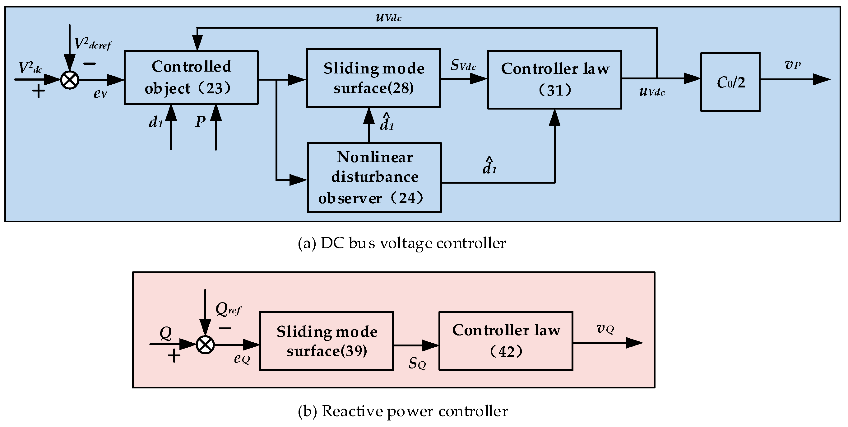
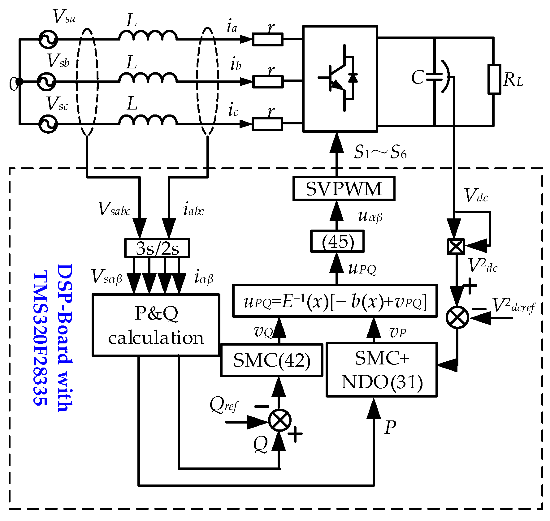
4. Design of Three-Phase PWM Rectifier Controller

Figure 2 illustrates the proposed robust direct power control strategy for the three-phase rectifier shown in Figure 1. As explained in Section 3.2, the active and reactive power controllers are designed separately since P and Q are uncoupled. The DC-side power model and active power model are treated as a unified system and controlled using the SMC with the NDO (SMC + NDO) method to regulate Vdc, as shown in Figure 2a. The sliding-mode controller is used to control the reactive power, as shown in Figure 2b. The following section will explain the process of designing controllers.

4.1. DC Bus Voltage Controller with SMC + NDO

Equation (20) reveals that the three-phase PWM rectifier is a nonlinear system that includes both matched and mismatched disturbances. However, most of the previous literature often neglects controller integrity by applying (1) and (6) to design the dual-loop controller, making it difficult to guarantee the global stability of the system [35]. Nevertheless, treating the DC-side power model and the active power model as a second-order model for designing controllers can lead to highly challenging control problems with mismatched disturbances [29]. Therefore, this paper applies the SMC + NDO method to design the DC bus voltage controller.

4.1.1. The NDO

From (9), it can be seen that the power model is established in the αβ coordinate system. However, Equation (9) shows that the power model is a DC system. This means that d ( d 1 ( t ) ) / d t will be zero when the system is stable. So, this paper makes the following assumptions:
Assumption 1. 
d1(t) is bounded and satisfies  lim t d ˙ 1 ( t ) = 0 .
For three-phase PWM rectifiers, the control objective is to ensure that Vdc strictly tracks the reference value Vdcref. Therefore, the voltage-tracking error is defined as
e V = V d c 2 V d c r e f 2
Substituting (21) into (20) yields
x ˙ V 1 = x V 2 + d 1 ( t ) x ˙ V 2 = u V d c + d 2 ( t ) y V = x V 1
where x V 1 x V 2 = e V 2 C 0 P , u V d c = 2 C 0 v P , d 2 ( t ) = 2 C 0 φ 1 , and y V = x V 1 .
From (22), it can be further concluded that
X ˙ V = f V ( x ) + g V 1 ( x ) u V d c + g V 2 ( x ) d 1 ( t ) y V = x V 1
where X V = x V 1 x V 2 , f V ( x ) = x V 2 d 2 ( t ) , g V 1 ( x ) = 0 1 , and g V 2 ( x ) = 1 0 .
In order to observe power disturbance d1(t), we designed the nonlinear disturbance observer as shown below.
p ˙ 1 = l g V 2 p 1 l g V 2 l X V + f V ( x ) + g V 1 ( x ) u V d c d ^ 1 = p 1 + l X V
where p1 is the auxiliary variable of the observer, d ^ 1 is the estimated value of d1, and l = [l1, l2] is the observer gain. From (24), it can be concluded that
d ^ ˙ 1 ( t ) = l g V 2 d ^ 1 ( t ) d 1 ( t )
Define disturbance estimation error as
e d ( t ) = d 1 ( t ) d ^ 1 ( t )
From (25) and Assumption 1, it can be concluded that
e ˙ d ( t ) + l g V 2 e d ( t ) = 0
According to (27), ed(t) will asymptotically converge to zero if lgV2 > 0. This implies that d ^ 1 can gradually track d1.

4.1.2. The SMC + NDO Controller

Assumption 2. 
The estimation error of system disturbance is bounded. There exists  e d * = sup e d ( t ) t > 0 .
TSMC cannot completely suppress mismatched disturbances. Therefore, this paper presents a new sliding-mode surface that integrates the estimation of mismatched disturbances into the traditional linear sliding surface, as shown in (28).
s V d c = x V 2 + c V d c x V 1 + d ^ 1 ( t )
where cVdc is the SMC parameter, cVdc > 0. In this paper, the Lyapunov stability theory is adopted to design the SMC controller. The design process is as follows.
Firstly, define the Lyapunov energy function as
V 1 = 1 2 s V d c 2
Combining Equations (22) and (28), the derivative of V1 can be obtained as
V ˙ 1 = s V d c s ˙ V d c = s V d c d 2 ( t ) + u V d c + c V d c ( x V 2 + d 1 ( t ) ) + d ^ ˙ 1 ( t )
Combining the Lyapunov stability condition and the principle of feedforward compensation, the following SMC controller is developed in this paper.
u V d c = c V d c x V 2 + d ^ 1 ( t ) k V d c sgn ( s V d c ) ρ 1 s V d c
where kVdc and ρ1 are the switching gain, kVdc > 0, ρ1 > 0. Substituting (31) into (30), we can further find
V ˙ 1 = s V d c d 2 ( t ) + ( c V d c + l g V 2 ) e d ( t ) k V d c sgn ( s V d c ) ρ 1 s V d c k V d c d 2 ( t ) ( c V d c + l g V 2 ) e d ( t ) s V d c ρ 1 s V d c 2 2 k V d c d 21 * ( t ) ( c V d c + l g V 2 ) e d ( t ) V 1 1 2 2 ρ 1 V 1
where e d * = sup t > 0 e d ( t ) , d 21 * = sup t > 0 d 2 ( t ) . If k V d c > d 2 ( t ) + ( c V d c + l g V 2 ) e d * max , then V ˙ 1 < 0 . This indicates that the designed SMC controller can drive the system to reach the sliding-mode surface within a finite time tr1, and tr1 is satisfied.
t r 1 1 ρ 1 ln 2 ρ 1 V 1 ( t 0 ) 1 2 + 2 k V d c d 21 * ( c V d c + l g V 2 ) e d * 2 k V d c d 21 * ( c V d c + l g V 2 ) e d *
when the system reaches the sliding-mode surface, from (22) and (28), we can find
x ˙ V 1 = c V d c x V 1 + e d ( t )
According to (26), (27), and (34), it obtains
x ˙ V 1 = c V d c x V 1 + e d ( t ) e ˙ d ( t ) = l g V 2 e d ( t ) + d ˙ 1 ( t ) x V 2 = c V d c x V 1 d ^ 1 ( t )
Lemma 1 
([15]). The system x ˙ = f ( t , x , u )
1.
If the origin of an unmotivated system is globally exponentially stable, then the system is input-state stable (ISS).
2.
If the system is ISS and satisfies  lim t u ( t ) = 0 m , then there is  lim t x ( t ) = 0 n .
Consider the following system
x ˙ V 1 = c V d c x V 1 + e d ( t ) e ˙ d ( t ) = l g V 2 e d ( t )
It is easy to see that system (36) is exponentially stable. It follows that (37) is ISS from Lemma 1(1).
x ˙ V 1 = c V d c x V 1 + e d ( t ) e ˙ d ( t ) = l g V 2 e d ( t ) + d ˙ 1 ( t )
Combining Assumption 1 and Lemma 1(2), it is known that the system states satisfy lim t x V 1 ( t ) = 0 and lim t e d ( t ) = 0 . That means that d ^ 1 and V d c 2 ultimately converge to d1 and Vdcref2, respectively. From (28), it follows that when the system reaches the sliding-mode surface, there is lim t x V 1 = 0 , and then there is lim t ( x V 2 + d ^ 1 ( t ) ) = 0 . This implies that the proposed SMC + NDO only requires one controller to regulate both DC bus voltage and active power. Furthermore, it suggests that the proposed SMC + NDO not only simplifies the control design but also improves robustness to both matched and mismatched power disturbances. According to (32), the proposed SMC + NDO can greatly reduce kVdc, and sliding-mode chattering is also effectively decreased consequently.

4.2. Reactive Power Controller with SMC

This section aims to ensure that Q follows the reference power Qref. To improve the robustness and reduce the chattering, SMC with the exponential convergence law is applied to design the reactive power controller. Define the error eQ = QQref, and by combining (20), we can find
d Q d t = v Q + d 3 ( t )
Select the sliding-mode surface as
s Q = e Q
And the Lyapunov function is defined as
V 2 = 1 2 s Q 2
Combining (38)–(40), the derivative of V2 can be obtained as
V ˙ 2 = s Q Q ˙ Q ˙ r e f = s Q v Q + d 3 ( t )
Based on the Lyapunov stability condition, we designed the sliding-mode feedback law as
v Q = ρ 2 s Q k Q sgn ( s Q )
where kQ, ρ2 is the switching gain, kQ > 0, ρ2 > 0. Substituting (42) into (41) yields
V ˙ 2 k Q φ 2 s Q ρ 2 s Q 2 = 2 k Q d 3 ( t ) V 2 1 2 ρ 2 s Q 2 2 k Q d 3 * ( t ) V 2 1 2 2 ρ 2 V 2
where d 3 * ( t ) = sup t > 0 d 3 ( t ) , From Equation (43), it can be seen that when k Q > d 3 * ( t ) , the system is stable and reaches the sliding-mode surface within a finite time tr2. The reaching time tr2 is satisfied.
t r 2 1 ρ 2 ln 2 ρ 2 V 2 1 2 ( t 0 ) + 2 k Q φ 2 * 2 k Q φ 2 *
From (3), the control input signals u and u are, respectively,
u r α = V s α u P V s β u Q V s 2 u r β = V s β u P + V s α u Q V s 2
Based on the above analysis, the block diagram of the RDPC is illustrated in Figure 3.
The simulation model of the proposed RDPC is depicted in Figure 4.

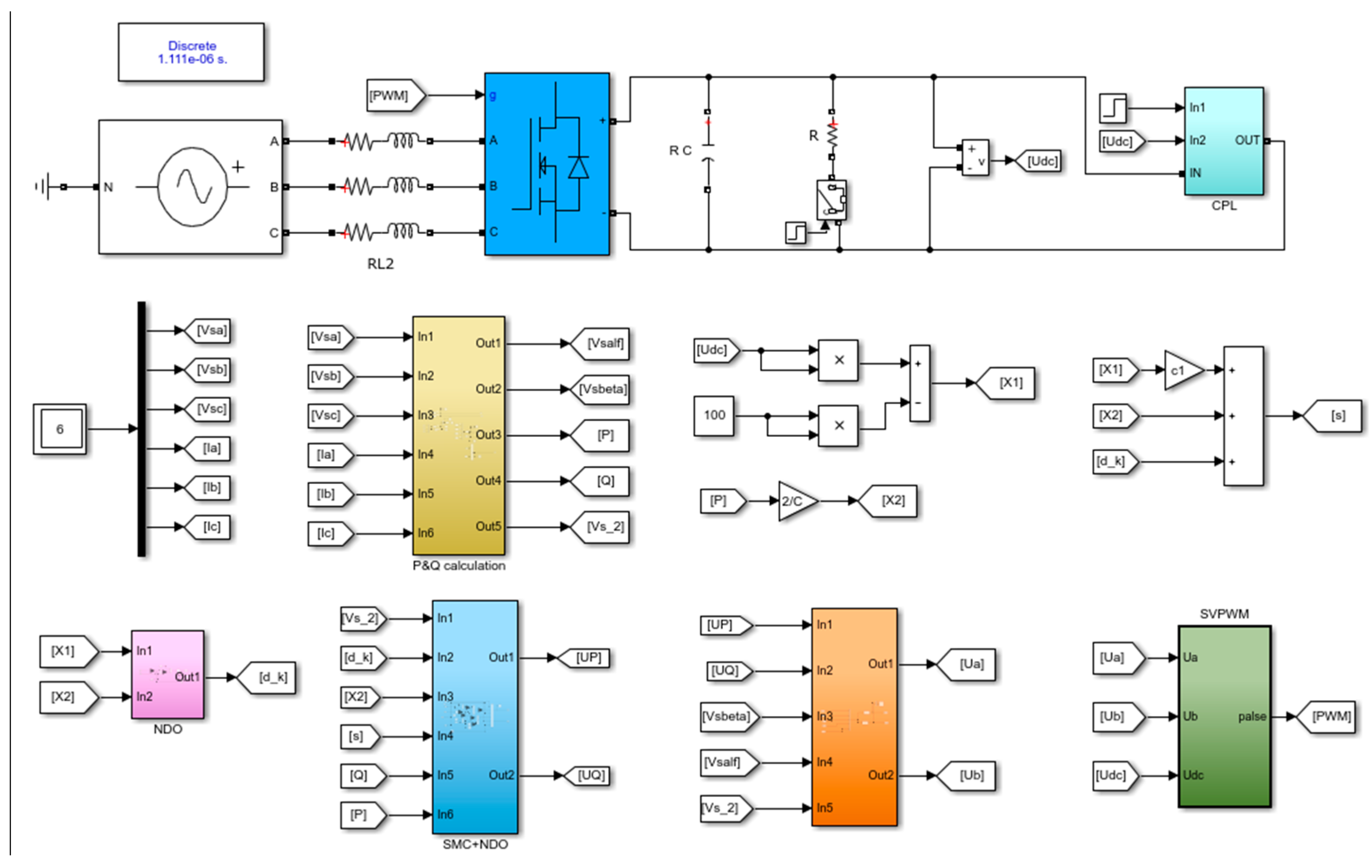
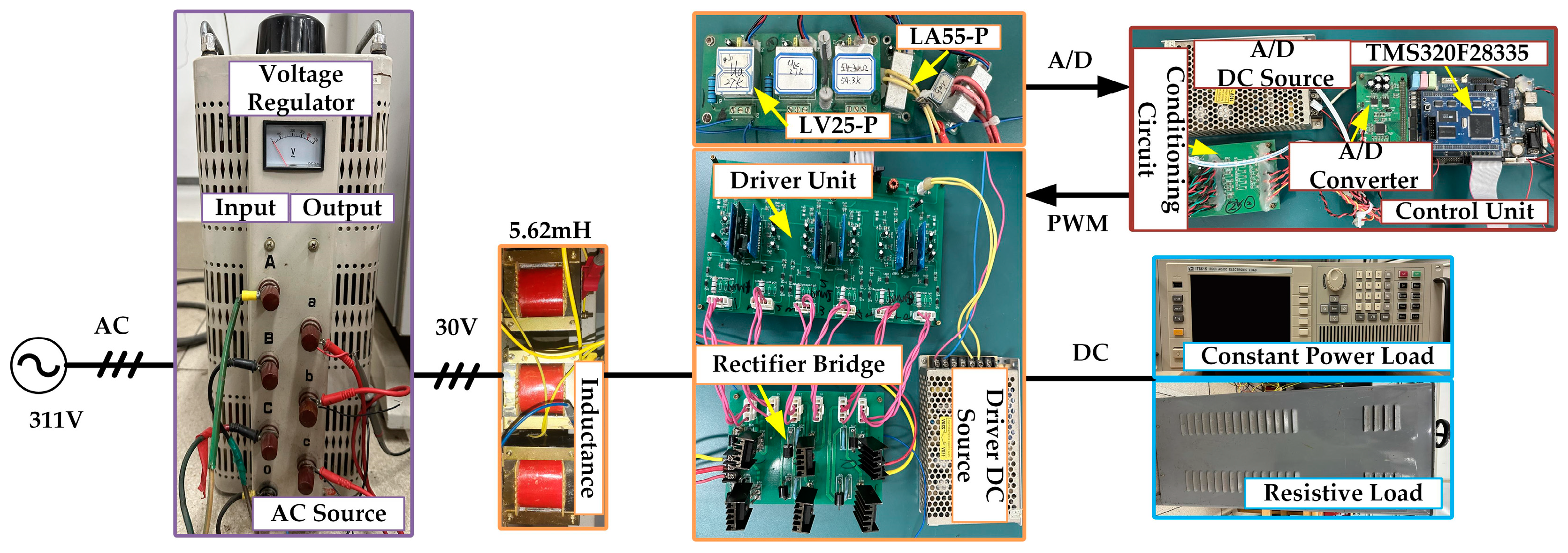
5. Simulation and Experimental Verification

In this paper, MATLAB/Simulink is used for simulation. The experimental platform is depicted in Figure 5, and includes LV-25P and LA-55P sensors for voltage and current, respectively. The power-switching device is IRFP460, and the control algorithm is implemented through TMS320F28335. The main circuit parameters are shown in Table 1.
To verify the superiority of the RDPC, we performed experimental and simulation comparisons with the dual-loop PI (DL-PI) control and the TSMC. The TSMC is shown in (46) and (47), where (46) represents the DC bus voltage controller and (47) represents the reactive power controller. As three-phase PWM rectifiers typically operate at the unity power factor, Qref is set to zero. The control parameters are detailed in Table 2.
s v d c _ S M C = x ˙ V 1 + c 1 x V 1 v P = k p sgn ( s v d c _ S M C ) c 1 x V 2
s Q _ S M C = e Q v Q = k q sgn ( s Q )
where kp and kq represent the switching gains of P and Q controllers in TSMC, respectively, c1 is the TSMC parameter.
The control parameters are detailed in Table 2. The parameters’ design procedure for the RDPC is summarized as follows.
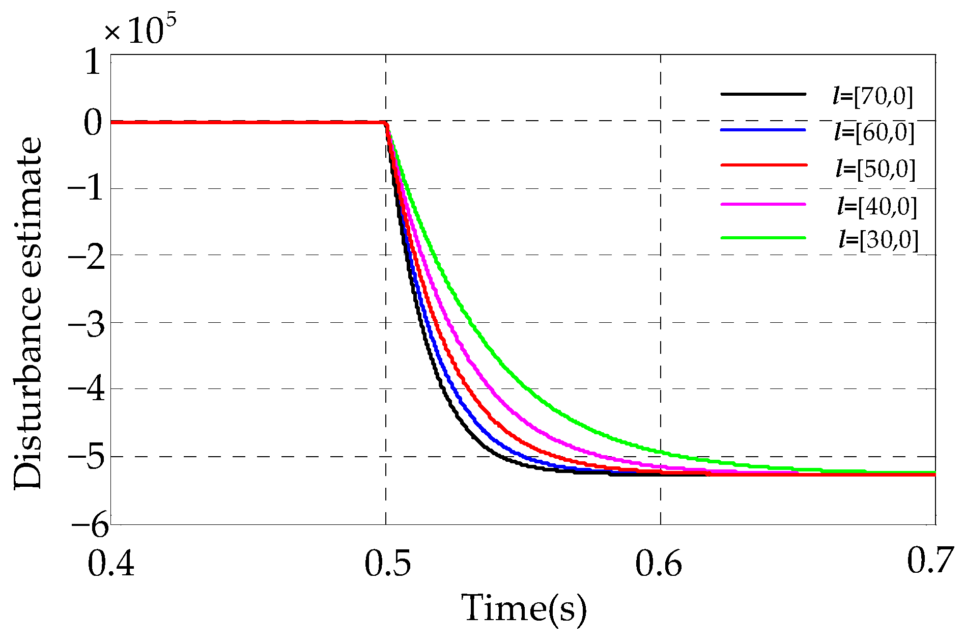
  • The criterion for the rectification of the observer gain l: First, l must be within the defined range (l > 0). Second, it is observed from Equation (27) and Figure 6 that a larger l results in a faster convergence rate. However, it should be noted that a larger l will lead to a larger switching gain kVdc, as defined in Equation (32), which increases the chattering. Therefore, in actual engineering applications, it is important to avoid selecting extreme l. Furthermore, when l exceeds [50,0], the improvement in dynamic performance shown in Figure 6 is not significant, so we set the l value to [50,0];
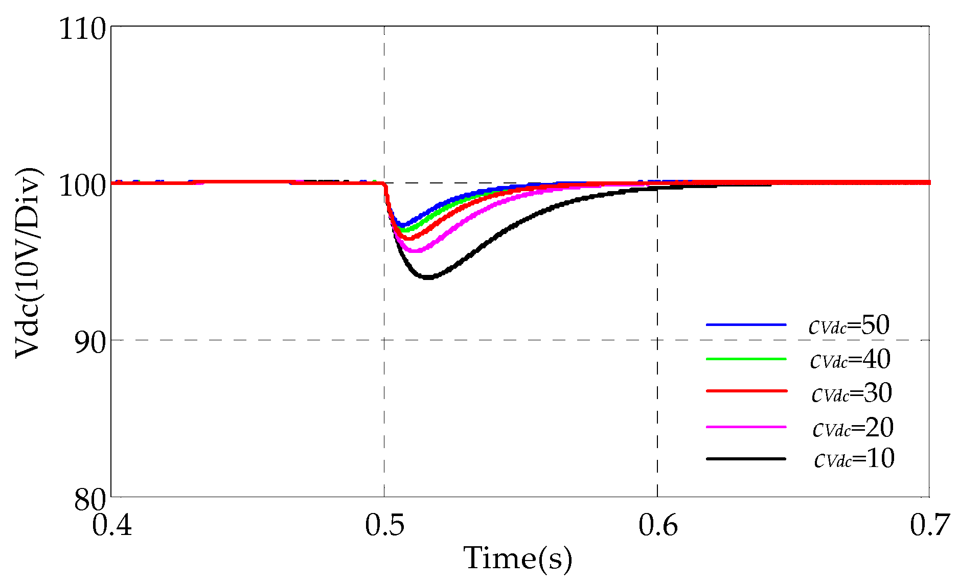
  • The criterion for the rectification of the SMC parameter cvdc: First, cvdc is chosen to be within the defined range (cvdc > 0). Second, as shown in Figure 7, a larger cvdc results in faster convergence and smaller voltage drop. However, a larger cvdc will lead to a larger switching gain kVdc, as defined in Equation (32), which increases the chattering. Furthermore, when cvdc exceeds 30, the improvement in dynamic performance shown in Figure 7 is not significant, so we set cvdc value to 30;
  • The criterion for the rectification of the switching gain kVdc, kQ, ρ1, and ρ2: Based on the selected l and cvdc, kVdc and kQ should be chosen within the defined in Equations (32) and (43). Furthermore, increasing ρ1 and ρ2 leads to a faster convergence rate. To reduce sliding-mode chattering, it is recommended to decrease kVdc and kQ.

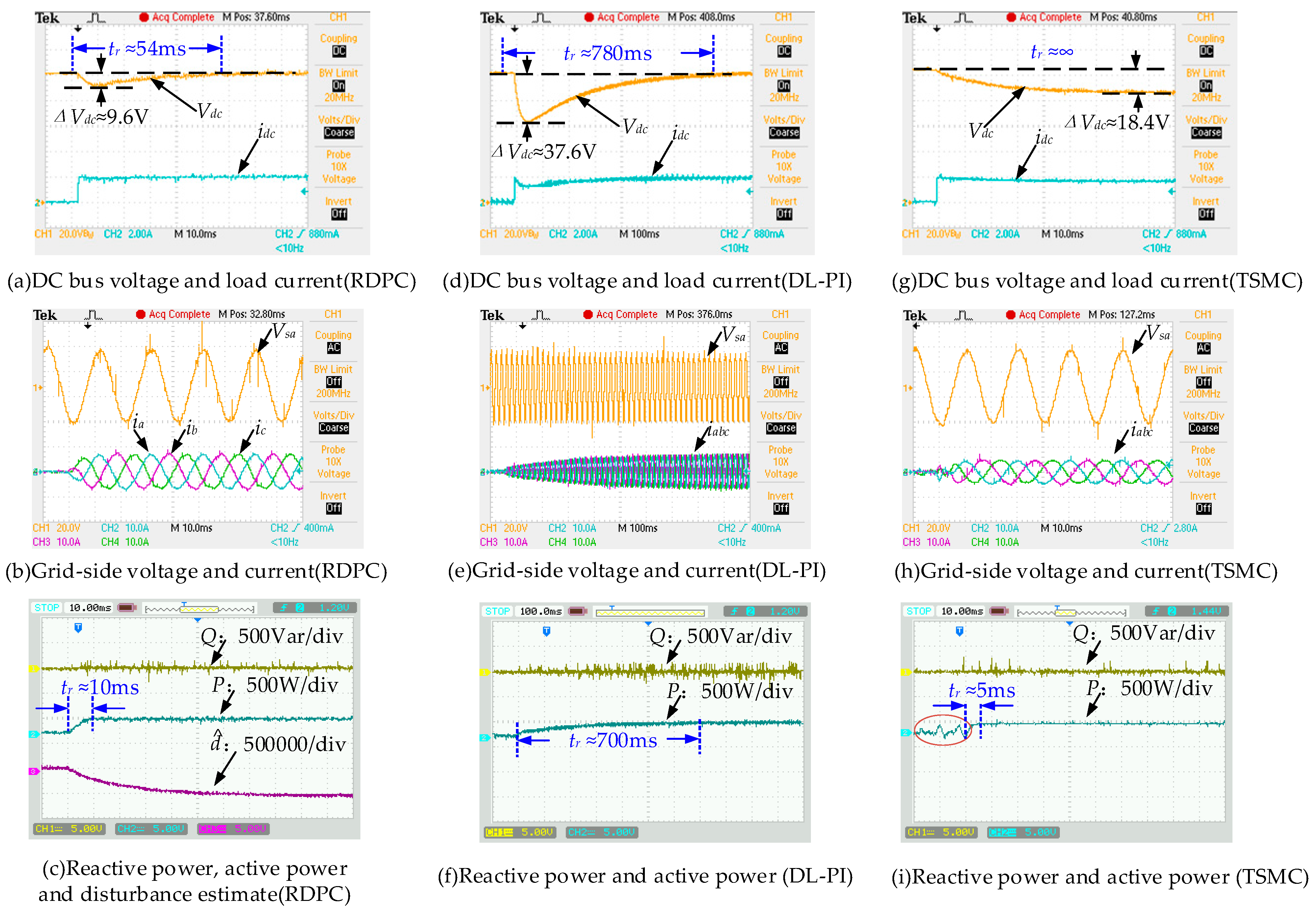
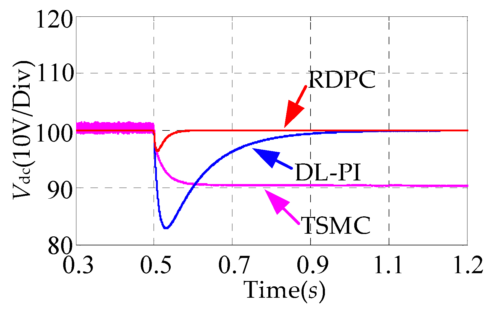
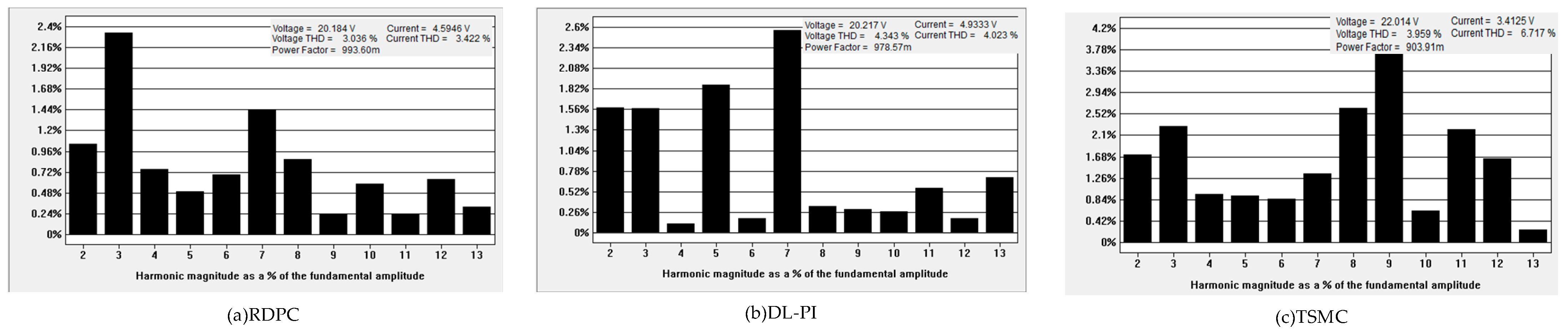
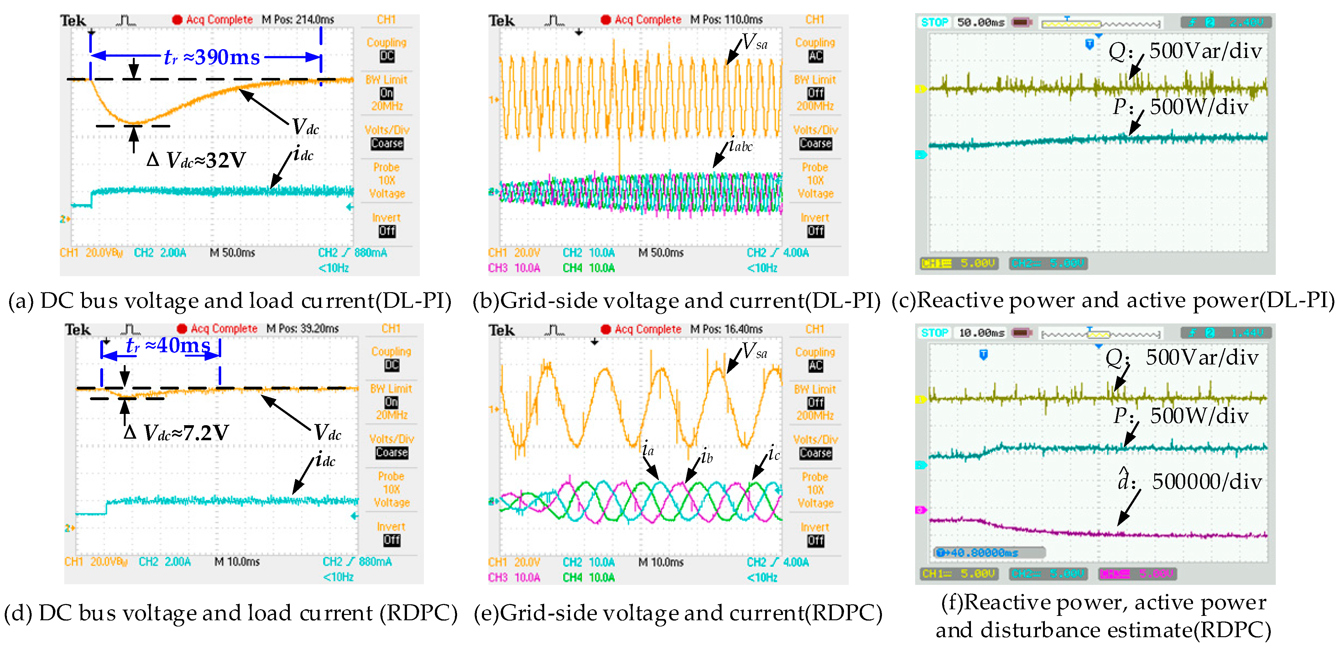
5.1. Dynamic and Steady-State Performance at Nominal Parameters

In this case, the load changes from no load to a load composed of a resistor of 50 Ω. Figure 8 and Figure 9 show the transient response of the DC bus voltage under three control methods; the general trends of the experimental waveforms are consistent with the simulated waveforms. In Figure 8 and Figure 9, one can observe that both the DL-PI control and the RDPC can regulate the DC bus voltage to the desired value of 100 V. However, the RDPC exhibits superior dynamic performance with a shorter transition time tr and less of a DC bus voltage drop ΔVdc. The reason is that the RDPC can compensate for disturbances in real time through the NDO, which enhances the resistance to mismatched disturbances. The TSMC is unable to completely suppress mismatched disturbances. Consequently, when the load is 50 Ω, the DC bus voltage does not reach 100 V, as depicted in Figure 8 and Figure 9. In contrast, the RDPC achieves simultaneous the regulation of DC bus voltage and active power through a single-loop control structure. On the other hand, the inner loop (current loop) in the DL-PI control is equivalent to a first-order inertial element, which causes a certain control delay. As a result, the dynamical response of the DL-PI is slower than that of the RDPC with a single-loop control structure.
Figure 9b,e,h show the steady-state current waveforms with the DL-PI, TSMC, and the RDPC. Figure 10 presents the power factor (PF), the total harmonic distortion (THD), and the current spectrum for the a-phase current. Comparing PF and current spectrum in Figure 10a–c, the RDPC has a better performance. Notably, the fifth and seventh harmonics are reduced compared to the DL-PI. The THD values for DL-PI are 4.023% (ia), 4.007% (ib), and 4.062% (ic). The THD values for TSMC are 6.717% (ia), 6.037% (ib), and 6.642% (ic), while the THD for the RDPC are 3.422% (ia), 3.207% (ib), and 2.799% (ic). The reason for this difference is that the RDPC considers the DC bus voltage and active power as a whole and applies the Lyapunov stability theory to design the controller, ensuring good stability over the whole load range. Meanwhile, it can be observed that the TSMC and RDPC have the same single-loop control structure, but the THD of the TSMC is higher than that of the RDPC. This is because the TSMC requires a large switching gain kp to suppress the mismatched disturbances, and a large switching gain kp can cause severe chattering, which leads to current distortion.
The transient responses of P and Q are also tested. Experimental results with the DL-PI, RDPC, and TSMC are shown in Figure 9c, Figure 9f, and Figure 9i, respectively. From Figure 9c,f, it is evident that P can converge quickly and accurately to 250 W (including the 200W load power as well as the power lost via the inductor, etc.), and the reactive power is stable near zero. This result demonstrates that both the RDPC and DL-PI exhibit good control accuracy for both P and Q. Figure 9c shows that Q always remains zero at the instant of P mutation, indicating that the RDPC effectively achieves the complete decoupling of P and Q using the exact feedback linearization method. However, Figure 9i reveals a significant error between P and the reference power due to the challenge of the TSMC in achieving the complete suppression of the mismatched power disturbances. From Figure 9c,f,i, it can be observed that the transition process times of P are 10 ms (RDPC), 700 ms (DL-PI) and 5 ms (TSMC), respectively. The results demonstrate that both the RDPC and TSMC, under the single-loop control structure, significantly enhance the dynamic response speed of the power control compared with the DL-PI. These findings demonstrate the effectiveness of the three-phase PWM single-loop control structure proposed in this paper. Based on the comparison of Figure 9c,i, it is known that the dynamic response time of the RDPC is slightly longer than that of the TSMC. This is primarily because the TMSC employs large robust switching gains in Equation (46) for power-disturbance compensation, while the RDPC mainly utilizes an integral-type NDO for power-disturbance compensation. Theoretically, the response speed of the NDO is inevitably slower than the robust switching gain. However, from the engineering application point of view, the power control speed of the RDPC has met the practical engineering requirements.
Figure 9c shows the dynamic response of the NDO. It can be seen that d ^ 1 exponentially converges to a steady-state value (≈−5 × 10⁵), verifying the correctness of (27). d ^ 1 is composed of load power, unmodeled dynamics, and parameter uncertainty, which makes it greater than the load power (≈−4 × 10⁵). In Figure 9i, the active power exhibits oscillations during the no-load operation. This is because we selected a switching gain for the TSMC that achieves a balance between stability and chattering under the rated load. However, this switching gain is too large for the no-load operation. In contrast, the RDPC uses the NDO to compensate for mismatched disturbances, which allows for a very small switching gain.

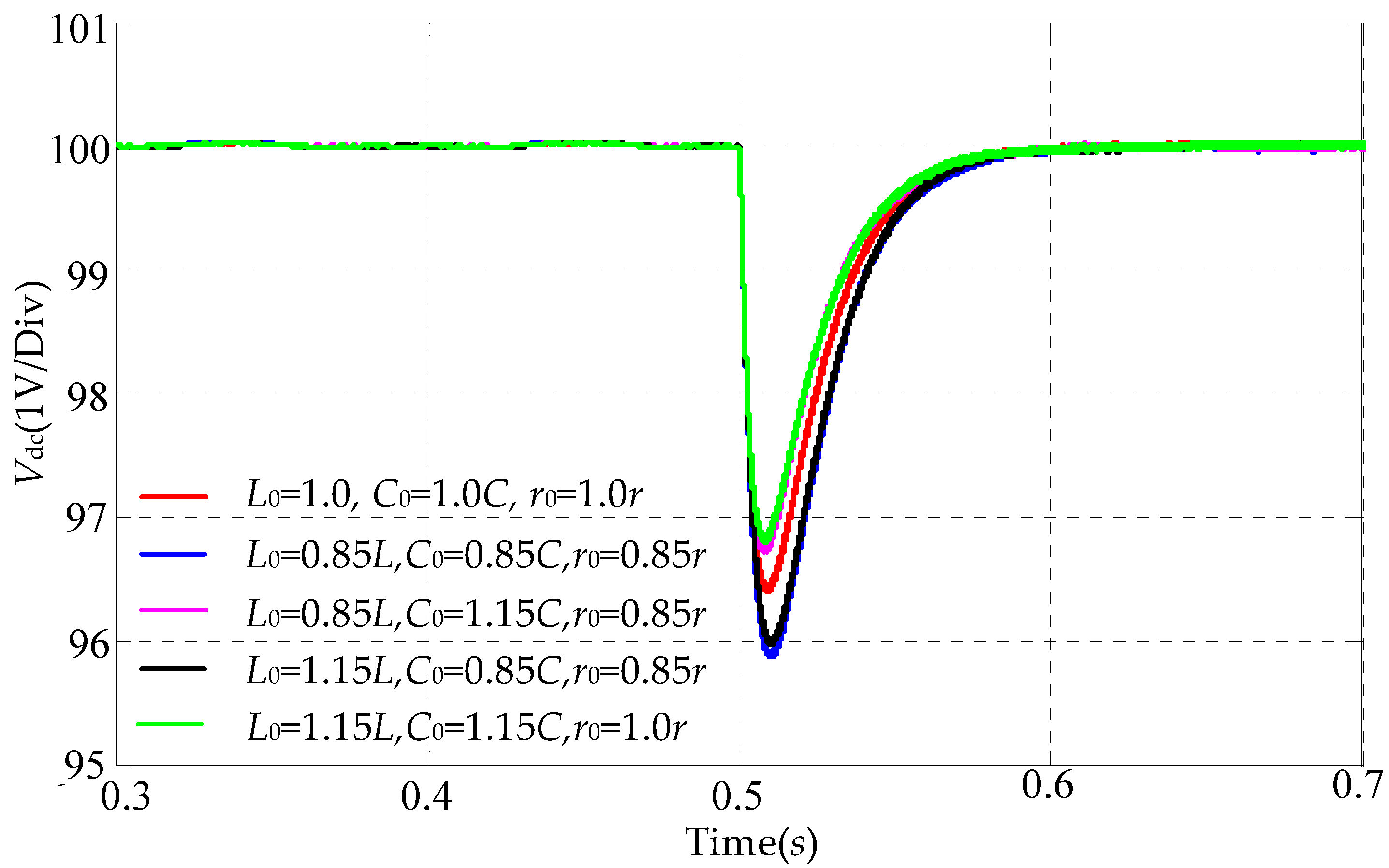
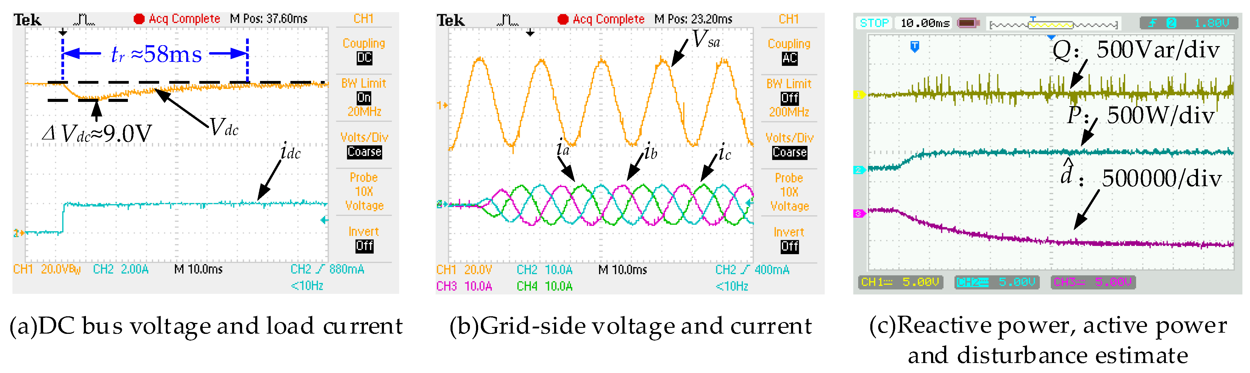
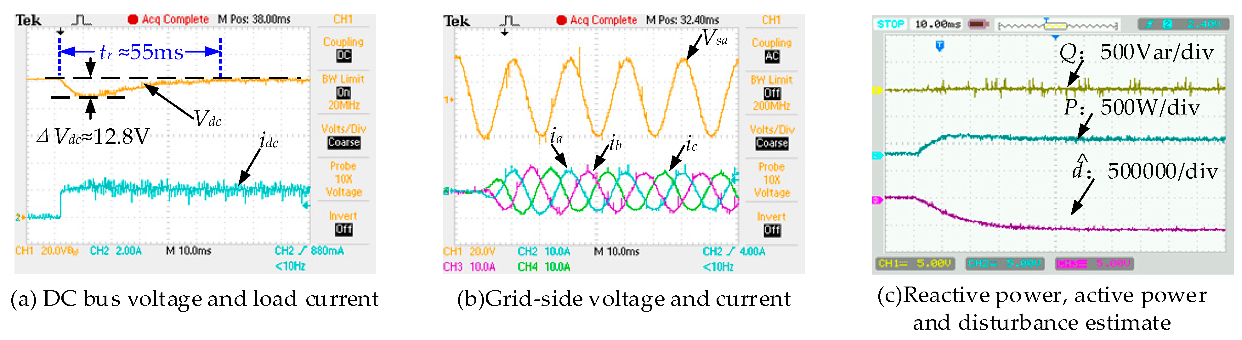
5.2. Parameter Robustness

This section proves the robustness of the proposed RDPC scheme against parameter uncertainties. To evaluate the robustness against the parameter uncertainties, the values of L0, C0, and r0 are set in variations. It is important to note that we have changed the parameters in the control system to evaluate the robustness of the control, as this method avoids the degradation of filtering performance due to physical changes in an L filter and C filter [36]. Figure 11 and Figure 12 show the simulation and experimental results with the parameter uncertainties. Table 3 summarizes transient and steady performances under these uncertainties. The results indicate that the current THD, DC bus voltage drop, and transient time have not changed significantly, confirming the strong robustness of the RDPC for parameter uncertainties.

5.3. Constant Power Load

We also tested the RDPC performance when a CPL is connected to the DC microgrid. The CPL steps from 100 W to 200 W. Figure 13a–f show dynamic response waveforms with the DL-PI and the RDPC. The proposed RDPC demonstrated better dynamic performance than the DL-PI. When L0 = 0.85L, C0 = 1.15C, and r0 = 0.85r, dynamic response waveforms with the RDPC are shown in Figure 14a–c. The results indicate that the RDPC remains insensitive to parameters even with the CPL. Additionally, the NDO exhibits excellent estimation performance under parameter uncertainties and the CPL. Meanwhile, the RDPC achieves stability of the DC bus voltage without requiring passive damping, as stated in [3].

6. Conclusions

In this paper, a novel RDPC has been proposed for the three-phase PWM rectifier by taking advantage of the single-loop control structure. Compared to traditional dual-loop direct power control, the proposed RDPC has a simpler control structure, a better steady-state, and better dynamic performance using the exact-feedback linearization theory to linearize the nonlinear power model of the rectifier, achieving the decoupling of active and reactive power. To deal with the matched and mismatched active power disturbances, sliding-mode controllers have been designed via NDO technology in the DC bus-tracking control. A sliding-mode-controller-based exponential convergence law has been developed to deal with the matched reactive power disturbances. The Lyapunov stability theory has proved that the designed controller is globally stable. Finally, the simulation and experimental results on the three-phase PWM rectifier have demonstrated that compared with the DL-PI and the TSMC, the proposed RDPC effectively has a remarkably shorter transient time, a rather smaller DC bus voltage drop and sliding-mode chattering, and stronger robustness to the mismatched and matched disturbances. Meanwhile, when a CPL is connected to the DC microgrid, the proposed RDPC still has the best steady state and dynamic performance, even with parameter uncertainties. The proposed RDPC can be extended to other converters, such as three-phase three-level Neutral Point Clamped (NPC) rectifiers; therefore, it has broad theoretical and engineering application value.

Author Contributions

Conceptualization, B.H.; methodology, B.H.; formal analysis, B.H.; investigation, B.H.; writing—original draft preparation, B.H. and J.Q.; writing—review and editing, B.H., J.Q. and H.L.; visualization, B.H., J.Q. and H.L.; supervision, H.L.; project administration, B.H. and H.L.; funding acquisition, B.H. All authors have read and agreed to the published version of the manuscript.

Funding

This research was funded in part by National Natural Science Foundation of China, grant number 51705003, and in part by Shaanxi University of Technology Talent Launch Program, grant number SLGRCQD2122, and in part by Shaanxi University of Technology Fund Program, grant number SLG1816.

Data Availability Statement

The data presented in this study are available in this article.

Conflicts of Interest

The authors declare no conflicts of interest.

References

  1. Jiao, Q.; Hosseini, R.; Cuzner, R.M. A comparison between silicon carbide based current source rectifier and voltage source rectifier for applications in community DC microgrid. In Proceedings of the 2016 IEEE International Conference on Renewable Energy Research and Applications (ICRERA), Birmingham, UK, 20–23 November 2016; pp. 544–549. [Google Scholar]
  2. Wu, B.; Gao, Z.; Zhou, X.; Ma, Y.; Wang, C. Research and Simulation of DC Microgrid Three-Phase AC-DC Converter Control Strategy Based on Double Loop. IEEE Access 2020, 8, 186448–186461. [Google Scholar] [CrossRef]
  3. Cespedes, M.; Xing, L.; Sun, J. Constant-Power Load System Stabilization by Passive Damping. IEEE Trans. Power Electron. 2011, 26, 1832–1836. [Google Scholar] [CrossRef]
  4. Malinowski, M.; Kazmierkowski, M.P.; Trzynadlowski, A.M. A comparative study of control techniques for PWM rectifiers in AC adjustable speed drives. IEEE Trans. Power Electron. 2003, 18, 1390–1396. [Google Scholar] [CrossRef]
  5. Xie, Z.; Wu, W.; Chen, Y.; Gong, W. Admittance-Based Stability Comparative Analysis of Grid-Connected Inverters with Direct Power Control and Closed-Loop Current Control. IEEE Trans. Ind. Electron. 2021, 68, 8333–8344. [Google Scholar] [CrossRef]
  6. Yan, S.; Yang, Y.; Hui, S.Y.; Blaabjerg, F. A Review on Direct Power Control of Pulse-width Modulation Converters. IEEE Trans. Power Electron. 2021, 36, 11984–12007. [Google Scholar] [CrossRef]
  7. Gil-Gonzalez, W.; Escobar-Mejia, A.; Montoya-Giraldo, O.D. Model Predictive Direct Power Control Applied to Grid-Connected Voltage Source Inverters. In Proceedings of the 2020 IEEE 11th International Symposium on Power Electronics for Distributed Generation Systems (PEDG), Dubrovnik, Croatia, 28 September–1 October 2020; pp. 610–614. [Google Scholar]
  8. Razali, A.M.; Rahman, M.A.; George, G.; Rahim, N.A. Analysis and Design of New Switching Lookup Table for Virtual Flux Direct Power Control of Grid-Connected Three-Phase PWM AC–DC Converter. IEEE Trans. Ind. Appl. 2015, 51, 1189–1200. [Google Scholar] [CrossRef]
  9. Lee, S.S.; Heng, Y.E. Table-based DPC for grid connected VSC under unbalanced and distorted grid voltages: Review and optimal method. Renew. Sustain. Energy Rev. 2017, 76, 51–61. [Google Scholar] [CrossRef]
  10. Malinowski, M.; Jasinski, M.; Kazmierkowski, M.P. Simple Direct Power Control of Three-Phase PWM Rectifier Using Space-Vector Modulation (DPC-SVM). IEEE Trans. Ind. Electron. 2004, 51, 447–454. [Google Scholar] [CrossRef]
  11. Gui, Y.; Li, M.; Lu, J.; Golestan, S.; Guerrero, J.M.; Vasquez, J.C. A Voltage Modulated DPC Approach for Three-Phase PWM Rectifier. IEEE Trans. Ind. Electron. 2018, 65, 7612–7619. [Google Scholar] [CrossRef]
  12. Moreno, J.C.; Espi Huerta, J.M.; Gil, R.G.; Gonzalez, S.A. A Robust Predictive Current Control for Three-Phase Grid-Connected Inverters. IEEE Trans. Ind. Electron. 2009, 56, 1993–2004. [Google Scholar] [CrossRef]
  13. Yang, H.; Zhang, Y.; Liang, J.; Liu, J.; Zhang, N.; Walker, P.D. Robust Deadbeat Predictive Power Control with a Discrete-Time Disturbance Observer for PWM Rectifiers Under Unbalanced Grid Conditions. IEEE Trans. Power Electron. 2019, 34, 287–300. [Google Scholar] [CrossRef]
  14. Slotine, J.-J.E.; Li, W. Applied Nonlinear Control; Prentice Hall: Englewood Cliffs, NJ, USA, 1991. [Google Scholar]
  15. Khalil, H.K. Nonlinear Systems, 3rd ed.; Prentice-Hall: Englewood Cliffs, NJ, USA, 2006. [Google Scholar]
  16. Eltoum, M.A.M.; Al-Mahzamah, F.; Ferik, S.E. Feedback Linearization Sliding Mode Control of Three-Phase Grid-tied AC/DC PWM Converter. In Proceedings of the 2020 17th International Multi-Conference on Systems, Signals & Devices (SSD), Monastir, Tunisia, 20–23 July 2020; pp. 1116–1121. [Google Scholar]
  17. Wai, R.; Yang, Y. Design of Backstepping Direct Power Control for Three-Phase PWM Rectifier. IEEE Trans. Ind. Appl. 2019, 55, 3160–3173. [Google Scholar] [CrossRef]
  18. Roy, T.K.; Mahmud, M.A.; Islam, S.N.; Rajasekar, N.; Muttaqi, K.M.; Oo, A.M.T. Robust Adaptive Direct Power Control of Grid-Connected Photovoltaic Systems. In Proceedings of the 2020 IEEE International Conference on Power Electronics, Smart Grid and Renewable Energy (PESGRE2020), Cochin, India, 2–4 January 2020; pp. 1–6. [Google Scholar]
  19. Wang, Y.; Li, Y.; Huang, S. An Improved Sliding Mode Direct Power Control Strategy Based on Reactive Power Compensation for Vienna Rectifier. IEEE Access 2022, 10, 15469–15477. [Google Scholar] [CrossRef]
  20. He, T.; Lu, D.D.; Li, L.; Zhang, J.; Zheng, L.; Zhu, J. Model-Predictive Sliding-Mode Control for Three-Phase AC/DC Converters. IEEE Trans. Power Electron. 2018, 33, 8982–8993. [Google Scholar] [CrossRef]
  21. Gui, Y.; Blaabjerg, F.; Wang, X.; Bendtsen, J.D.; Yang, D.; Stoustrup, J. Improved DC-Link Voltage Regulation Strategy for Grid-Connected Converters. IEEE Trans. Ind. Electron. 2021, 68, 4977–4987. [Google Scholar] [CrossRef]
  22. Liu, J.; Yin, Y.; Luo, W.; Vazquez, S.; Franquelo, L.G.; Wu, L. Sliding Mode Control of a Three-Phase AC/DC Voltage Source Converter Under Unknown Load Conditions: Industry Applications. IEEE Trans. Syst. Man Cybern. Syst. 2018, 48, 1771–1780. [Google Scholar] [CrossRef]
  23. Ma, H.; Xie, Y.; Shi, Z. Improved direct power control for Vienna-type rectifiers based on sliding mode control. IET Power Electron. 2016, 9, 427–434. [Google Scholar] [CrossRef]
  24. Guo, T.; Sun, Z.; Wang, X.; Li, S.; Zhang, K. A Simple Current-Constrained Controller for Permanent-Magnet Synchronous Motor. IEEE Trans. Ind. Inform. 2019, 15, 1486–1495. [Google Scholar] [CrossRef]
  25. Wang, Y.; Yu, H.; Liu, Y. Speed-Current Single-Loop Control with Overcurrent Protection for PMSM Based on Time-Varying Nonlinear Disturbance Observer. IEEE Trans. Ind. Electron. 2021, 69, 179–189. [Google Scholar] [CrossRef]
  26. Zhang, Z.; Liu, X.; Yu, J. Time-Varying Disturbance Observer Based Improved Sliding Mode Single-Loop Control of PMSM Drives with a Hybrid Reaching Law. IEEE Trans. Energy Convers. 2023, 38, 2539–2549. [Google Scholar] [CrossRef]
  27. Ma, W.; Zhang, B.; Qiu, D. Robust Single-Loop Control Strategy for Four-Level Flying-Capacitor Converter Based on Switched System Theory. IEEE Trans. Ind. Electron. 2023, 70, 7832–7844. [Google Scholar] [CrossRef]
  28. Zhao, F.; Liu, Y.; Yao, X.; Su, B. Integral sliding mode control of time-delay systems with mismatching uncertainties. J. Syst. Eng. Electron. 2010, 21, 273–280. [Google Scholar] [CrossRef]
  29. Chen, W.; Yang, J.; Guo, L.; Li, S. Disturbance-Observer-Based Control and Related Methods—An Overview. IEEE Trans. Ind. Electron. 2016, 63, 1083–1095. [Google Scholar] [CrossRef]
  30. Cao, M.; Li, S.; Yang, J.; Zhang, K. Mismatched Disturbance Compensation Enhanced Robust H∞ Control for the DC-DC Boost Converter Feeding Constant Power Loads. IEEE Trans. Energy Convers. 2023, 38, 1300–1310. [Google Scholar] [CrossRef]
  31. Bodur, F.; Kaplan, O. Fixed-Time Sliding Mode Control for DC-DC Converters with both Matched and Mismatched Disturbances Based on Disturbance Observer. In Proceedings of the 2023 12th International Conference on Renewable Energy Research and Applications (ICRERA), Oshawa, ON, Canada, 29 August–1 September 2023; pp. 569–575. [Google Scholar]
  32. Boo, J.; Chwa, D. Integral Sliding Mode Control-Based Robust Bidirectional Platoon Control of Vehicles with the Unknown Acceleration and Mismatched Disturbance. IEEE Trans. Intell. Transp. Syst. 2023, 24, 10881–10894. [Google Scholar] [CrossRef]
  33. Wu, T.; Sun, K.; Kuo, C.; Chang, C. Predictive Current Controlled 5-kW Single-Phase Bidirectional Inverter with Wide Inductance Variation for DC-Microgrid Applications. IEEE Trans. Power Electron. 2010, 25, 3076–3084. [Google Scholar] [CrossRef]
  34. Wu, T.; Chang, C.; Lin, L.; Chang, Y.; Chang, Y. Two-Phase Modulated Digital Control for Three-Phase Bidirectional Inverter with Wide Inductance Variation. IEEE Trans. Power Electron. 2013, 28, 1598–1607. [Google Scholar] [CrossRef]
  35. Zhang, X.; He, J.; Hao, M. Stability Enhancement Methods of Inverters Based on Lyapunov Function, Predictive Control, and Reinforcement Learning; Springer Nature Singapore Pte Ltd.: Berlin/Heidelberg, Germany, 2023. [Google Scholar]
  36. Ghanes, M.; Trabelsi, M.; Abu-Rub, H.; Ben-Brahim, L. Robust Adaptive Observer-Based Model Predictive Control for Multilevel Flying Capacitors Inverter. IEEE Trans. Ind. Electron. 2016, 63, 7876–7886. [Google Scholar] [CrossRef]
Figure 1. Rectifier system in the DC microgrid.
Electronics 13 01476 g001
Figure 2. The design of the controllers for the three-phase PWM rectifier.
Electronics 13 01476 g002
Figure 3. The proposed RDPC for three-phase voltage-source PWM rectifier.
Electronics 13 01476 g003
Figure 4. The simulation model of the proposed RDPC.
Electronics 13 01476 g004
Figure 5. Three-phase PWM rectifier experimental platform.
Electronics 13 01476 g005
Figure 6. Disturbance estimate under different values of l.
Electronics 13 01476 g006
Figure 7. Disturbance estimate under different values of cvdc.
Electronics 13 01476 g007
Figure 8. Simulation waveforms when load steps from 0 Ω to 50 Ω.
Electronics 13 01476 g008
Figure 9. Experimental waveforms when load steps from 0 Ω to 50 Ω.
Electronics 13 01476 g009
Figure 10. Harmonic analysis under steady-state conditions.
Electronics 13 01476 g010
Figure 11. Simulation waveforms under parameter perturbation.
Electronics 13 01476 g011
Figure 12. Dynamic response under parameter perturbation (L0 = 0.85L, C0 = 1.15C, r0 = 0.85r, load steps from 0 Ω to 50 Ω).
Electronics 13 01476 g012
Figure 13. Dynamic response with DL-PI and RDPC (L0 = L, C0 = C, r0 = r, CPL steps from 100 W to 200 W).
Electronics 13 01476 g013
Figure 14. Dynamic response with RDPC (L0 = 0.85L, C0 = 1.15C, r0 = 0.85r, CPL steps from 0 W to 200 W).
Electronics 13 01476 g014
Table 1. System parameters.
MeaningParametersValueUnits
Grid voltage (peak voltage)Vm30V
Grid frequencyf50Hz
Filter inductanceL5.62mH
Equivalent resistancer1.2Ω
DC bus reference voltageVdcref100V
DC filtering capacitorC1000μF
Sampling frequencyfs9kHz
Table 2. Control parameters.
ControllersParameters Value
RDPCl[50,0]
cVdc30
kVdc1250.3
ρ1100
kQ20
ρ2100
DL-PIKp_P420
Ki_P2000
Kp_Q420
Ki_Q2000
Kp_Vdc30
Ki_Vdc300
TSMCc130
kp400,000
kq100,000
Table 3. Control-performance indicators proposed under parameter perturbation.
L0C0r0Grid-Side Current THD ΔVdc (V)tr (ms)
85%85%85%3.612%11.256
85%115%85%3.416%9.058
115%85%85%3.692%10.456
115%115%100%3.658%9.056
Disclaimer/Publisher’s Note: The statements, opinions and data contained in all publications are solely those of the individual author(s) and contributor(s) and not of MDPI and/or the editor(s). MDPI and/or the editor(s) disclaim responsibility for any injury to people or property resulting from any ideas, methods, instructions or products referred to in the content.

