
Research on Tracking Technique Based on BPSK-CSK Signals

1
Beijing Research Institute of Telemetry, Beijing 100076, China
2
College of Oceanography and Space Informatics, China University of Petroleum, Qingdao 266580, China
*
Author to whom correspondence should be addressed.
Electronics 2024, 13(8), 1517; https://doi.org/10.3390/electronics13081517
Submission received: 8 March 2024
/
Revised: 11 April 2024
/
Accepted: 15 April 2024
/
Published: 17 April 2024
Abstract
:The code-shift keying (CSK) modulation method can achieve higher information transmission rates without changing the spread spectrum signal bandwidth. In order to optimise the spread spectrum modulation and demodulation of GNSS signals, in addition to the signal structure, binary phase-shift keying (BPSK) and CSK signals using time-division multiplexing are proposed. A tracking method based on the BPSK-CSK signals is also proposed, which generates the P-branch local codes by fast Fourier transform to obtain the code-slice spacings for the E-branch and the L-branch local codes. Then, the tracked BPSK signals and tracked CSK signals are compared and analysed. Finally, the bit error rate (BER) and tracking error of each method are compared and analysed by comparing with the tracking of conventional BPSK signals and tracking of CSK signals, in order to verify the convergence process of the I-branch integral value. The BPSK-CSK signal tracking method proposed in this paper combines the high information transmission rate of CSK-modulated signals and the low BER of BPSK signals, and the results provide a solid foundation for high-precision GNSS services.
1. Introduction
With the development of modern GNSS signals, the future will see a surge in the number of users, a diversification of user ranges, an increase in information content, and a higher demand for real-time high accuracy. In order to achieve localisation in urban building environments, a higher information transfer rate is required [1,2,3,4]. The advantages of BPSK modulation are the simple modulation process and mature capture and tracking algorithms. However, with the rapid development of GNSS, the limitations of BPSK modulation are becoming more and more prominent. Firstly, the rapid increase in the number of navigation satellites leads to more and more congestion in the frequency band of navigation signals, and the problem of mutual interference of signals becomes more and more serious. Secondly, BPSK signals have limited ranging accuracy and poor multipath resistance, which cannot meet the demand for high-precision positioning. In order to increase the bit rate, the traditional methods are to increase the Pseudo Random Noise (PRN) code rate or reduce the PRN code length. However, the former increases the spectral width and the latter affects the orthogonality of PRN codes [5,6,7]. The emergence of CSK modulation can effectively solve the above problems and can effectively increase the bit rate to make the information rate flexible and variable [8,9,10].
CSK modulation has the following advantages over traditional BPSK modulation: firstly, it can realise non-coherent demodulation; secondly, there is no need to modify the symbol rate of the reference signal, the code rate, or the length of the PRN code when the original code bit rate is increased; thirdly, the flexibility of the code bit data rate is much higher; fourthly, the CSK modulation is a shift of the pseudo code sequence, which does not need to modify the information rate. The sequence is shifted without extensive hardware modifications. However, there are also problems such as that the synchronisation process is difficult to implement, the receiver complexity is high, and the number of correlators is much larger than BPSK [11,12,13].
CSK modulation can flexibly adjust the information transmission rate while keeping the main code period unchanged, which can satisfy a variety of application scenarios [14,15]. The CSK modulation used in the L6 signal of Japan’s Quasi-Zenith Satellite System (QZSS) achieves a symbol rate of 2000 bit/s, which is much higher than the 50 bit/s information transmission rate of the L1C/A signal of the Global Positioning System (GPS) information transmission rate [16]. In addition, scholars have investigated the use of CSK modulation in optical communications [17,18] and underwater acoustic communications [19] to achieve high-rate message transmission without carrier synchronization.
Compared with BPSK signals, CSK-modulated signals have a higher transmitted information rate and even achieve demodulation gain within the same master code period [20,21,22]. However, compared with BPSK, CSK consumes more resources and has higher computational complexity. For CSK signals, scholars have mainly studied the improvement of CSK modulation and demodulation algorithms, as well as the combination of coding techniques to improve the reliability of transmission [23,24,25,26]. The tracking algorithms for BPSK signals are relatively mature, and the research on CSK signal tracking is not sufficient, mainly focusing on reducing the number of correlators and the demodulation complexity. Literature [27] extends the definition of CSK signals and proposes a CSK capture tracking method, but this method is not applicable to standard CSK signals. Literature [28] proposed an improved tracking method for CSK signals, which reduces the implementation complexity at the expense of tracking accuracy. Literature [29] proposed an efficient demodulation algorithm based on chunked FFT, which combines parity chunked baseband data from the traditional time domain operation to the frequency domain operation, and effectively reduces the complexity of correlation value calculation. Literature [30] proposed a frequency domain demodulation algorithm for CSK signals based on partial-output FFTs, which reduces the computational complexity of demodulation by optimising the butterfly structure of conventional FFTs and computing nodes to eliminate irrelevant values.
In this paper, we propose to transmit BPSK signals and CSK signals using time-division multiplexing. Subsequently, we detail the BPSK-CSK signal model, propose a BPSK-CSK signal tracking method based on time-division multiplexing, compare and analyse the BER and tracking error with other tracking methods, and complete the validation of the method to compare, analyse, and reduce the computational complexity. The BPSK-CSK signal tracking method proposed in this paper combines the high information transmission rate of CSK-modulated signals and the low BER of BPSK signals, and the results provide a solid foundation for high-precision GNSS services.
2. Materials and Methods
2.1. Fundamentals of BPSK-CSK Signaling Theory
CSK Modulation and Demodulation
The CSK modulation technique is essentially a spread spectrum modulation; only the phase of the pseudo-code is cyclically shifted according to the different data sent to obtain a new code, which overcomes the limitation of the spreading gain on the data rate and improves the information transmission rate without changing the signal bandwidth, amplitude, and other parameters. Therefore, each cyclically shifted pseudocode can represent a CSK symbol. The receiving end identifies the pseudocode phase of a CSK symbol by demodulation, which means that the data coming from the sending end can be obtained [1].
CSK uses M orthogonal signals to transmit bits. The special feature of CSK modulation is that the symbols of each set of input bits are obtained from different cyclic shifts of a single elementary PRN sequence. In addition, each cyclic shift consists of an integer number of code slices and is assumed to be a full-cycle version of the basic pseudocode.
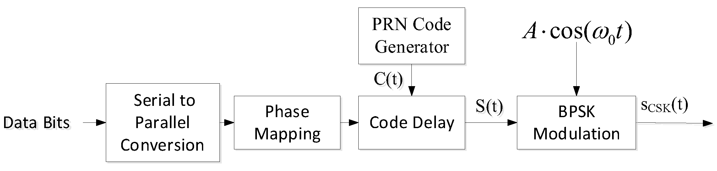
Figure 1 shows the CSK modulation flow. The phase of the pseudo-code for direct sequence spread spectrum modulation is always kept constant, i.e., only the pseudo-code with phase 0 is used for the direct sequence spread spectrum, while in CSK modulation, the basic pseudo-code generates M cyclically shifted pseudo-codes through the code slice delayer. In addition, the data stream with U bits in a group corresponds to one CSK symbol, which is mapped to obtain the corresponding CSK cyclically shifted sequence, thus generating one CSK symbol, which is finally transmitted through carrier modulation.
From the principle of CSK modulation, different pseudo-code phases represent different data. At the receiver side, it is only necessary to demodulate the pseudo-code phases, and then by searching the reflective table, you can know the modulated data in the pseudo-code period. Commonly used CSK demodulation methods are matched filter demodulation and FFT demodulation. Through demodulation, the correlation value between the received signal and each CSK cyclic code word can be obtained, and the cyclic code word with the largest correlation value is selected as the demodulated output.
The principle of matched filtering is to match correlate CSK symbols through a filter bank and select the CSK cyclic code word corresponding to the maximum value of the matched filter output as the demodulation of the transmitted symbols.
Matched filter demodulation is performed using two matched filter banks, in-phase and quadrature, where the input IF signal is mixed with the locally generated in-phase and quadrature carriers, respectively, and the mixed results are fed into the filter banks for matched correlation. Each filter bank contains M filters, and the cyclic shift sequences used by the filters are matched and correlated with the received signals. Finally, the correlation output is obtained by integrating and summing. Due to the good autocorrelation of the pseudocode, if the received CSK symbols are aligned with a certain cyclic shift sequence, the correlation output of that filter will have a significant peak, and the outputs of the other filters will be noise.
When the number M of CSK modulation is increased, the number of matched filter banks is also increased, and the complexity of demodulation will be further increased. In order to reduce the complexity of CSK demodulation, FFT-based demodulation can be used, and its demodulation principle is consistent with the principle of parallel code phase capture of satellite navigation signals. Figure 2 shows the principle diagram of CSK demodulation based on FFT.
2.2. BPSK-CSK Signal Model
In terms of signal structure, the CSK-modulated part and the BPSK-modulated part are inserted by synchronised time division multiplexing, i.e., both signals have the same time period. In the BPSK cycle, the navigation information is multiplied with the spread spectrum code and then transmitted to the carrier using BPSK modulation. In the CSK cycle, the spread spectrum code is shifted by CSK and then transmitted by BPSK modulation to the carrier. Figure 3 shows the schematic of time division multiplexing with BPSK modulation and CSK modulation.
The digital IF signal in the input tracking loop is:
where is the received BPSK periodic signal at moment ; is the received CSK periodic signal at moment ; C is the total signal power; is the navigational message symbol; is the periodic spreading code; is the spreading code after modulation by CSK; is the received signal frequency in Hz; is the carrier phase of the signal; and are additive Gaussian white noises; and the power spectral density is .
2.3. A BPSK-CSK Signal Tracking Method Based on Time-Division Multiplexing
The tracking method of this paper is shown in Figure 4, which consists of the carrier loop and the code loop. The difference with the traditional tracking loop is that the carrier loop updates the loop state intermittently, and the phase detector only updates the carrier loop phase error and the code ring phase error during the BPSK cycle.
In Figure 4, the whole tracking framework of the BPSK-CSK signal is represented. The input digital IF signal is restricted to the carrier loop replicated by the carrier for mixing and multiplying, which is multiplied by the sinusoidal replicated carrier in the I-branch, and multiplied by the cosine replicated carrier in the Q-branch; the mixing results of the I and Q-branch are, respectively, correlated to the E, P, and L codes after the code loop shifting, and the six coherent integral values are obtained after integral clearing. The six coherent integral values are obtained, and and are input into the carrier phase discriminator and carrier loop filter to maintain the consistency of the local and received carrier phases; , , , and are input into the code phase discriminator and code loop filter to maintain the consistency of the local and received code phases.
2.3.1. Carrier-Tracking Loop
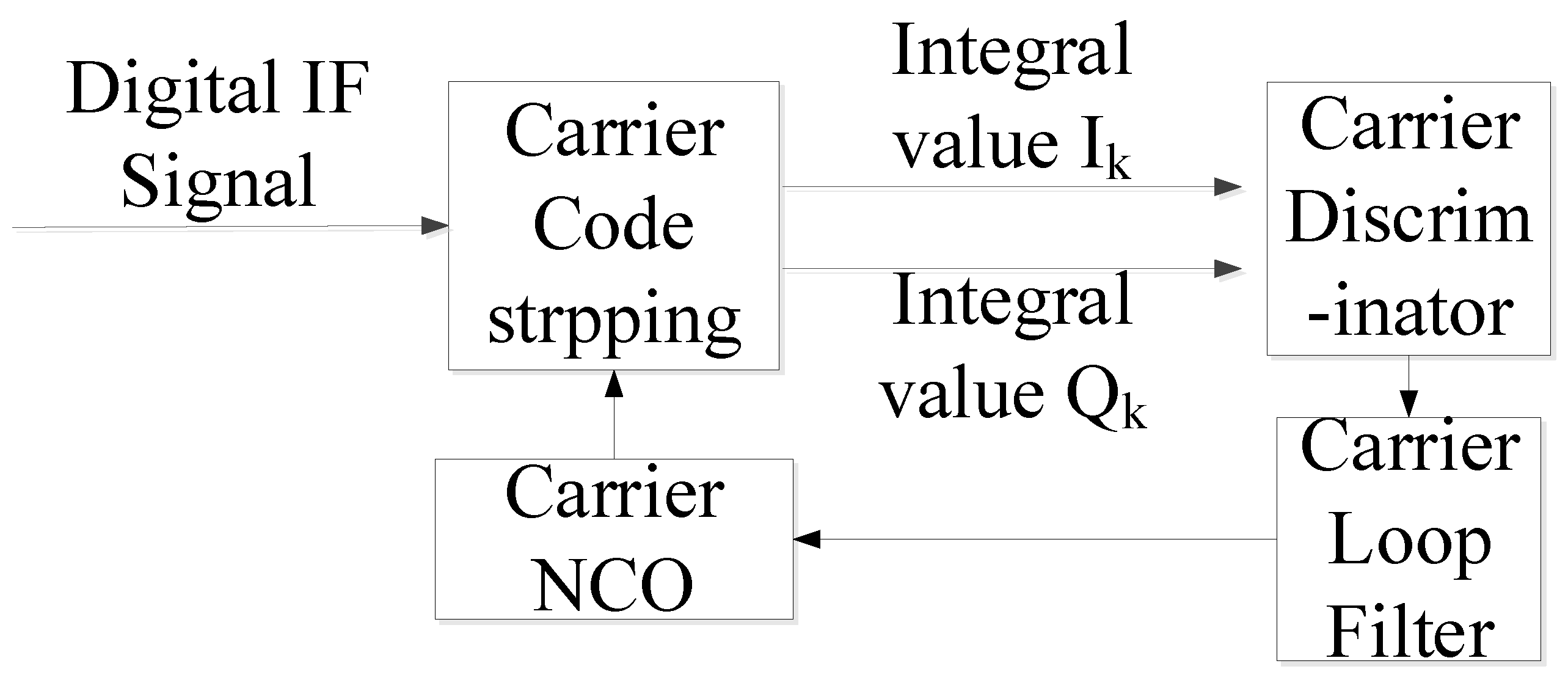
The carrier loop of the CSK signal is designed using Phase-Locked Loop (PLL). The carrier-tracking loop used in the CSK-tracking algorithm is shown in Figure 5.
When the coherent integration time is , the cumulative values of and in the kth segment are shown in Equation (3), where A is the amplitude, T is the sampling interval, N is the number of samples, f is the tracking frequency deviation, and and are the I-channel and Q-channel noise, respectively.
The PLL discriminator used in this paper is a two-quadrant arctangent discriminator. Its discriminator equation is shown in Equation (4), where is the noise. The PLL corresponding to the tracking frequency range is calculated as Equation (5).
In Figure 5, the carrier-tracking loop in this paper mainly adopts a phase-locked loop, which mainly consists of a carrier phase discriminator, a carrier loop filter, and a carrier NCO, and detects the phase difference between the carrier replicated by the carrier NCO and the carrier of the input digital intermediate frequency (IF) signal, then adjusts the phase of the replicated carrier accordingly according to the feedback loop. The phase of the two is kept consistent in order to strip out the carrier in the received signal.
2.3.2. Code-Tracking Loop
The basic code-tracking loop for CSK is the Delay-Locked Loop (DLL). The spreading codes of CSK signals have good autocorrelation and inter-correlation properties. The correlation can be maximised when codes of the same sequence are aligned. To improve accuracy, DLL will generate Early (E), Prompt (P), and Late (L) local codes.
The mixing results of the I and Q branches of the received signal after carrier separation are correlated with the E, P, and L branch replicated spreading codes, respectively, and here the E code is taken as an example, and the expression of the correlation operation result is:
where is the phase difference between the over-replicated code and the received code; is the code autocorrelation function; is the carrier phase difference. After the coherent integration time , the noise component , and after the ith update cycle, the overdrive autocorrelation amplitude is:
The design of the CSK code ring is shown in Figure 6. In this paper, the Noncoherent Early Minus Late Power (NELP) phase discriminator is used. Its calculation formula is shown in Equation (9):
where is the code phase difference after the BPSK cycle.
In Figure 6, the code-tracking loop in this paper adopts DLL, which is mainly composed of the code NCO, code phase discriminator, and code loop filter, and generates three local codes with different phases through the code NCO, which are E code, P code, and L code, respectively, and respectively correlates these three local codes with the received signal at the same time, compares them to derive the position of the main peak, and determines the phase difference between the local P code and the received signal number, so as to make the local code and the received code momentarily aligned.
When the correlation value of L code is maximum, the adjustment code generator decreases the code phase; when the correlation value of P code is maximum, it represents that the code-tracking loop tracks the signal correctly; and when the correlation value of E code is maximum, the adjustment code generator increases the code phase. After that, the pseudo-code phase difference is obtained by the code ring phase discriminator, and the code generator completes the dynamic adjustment of the whole code-tracking loop according to the code phase error to achieve the locking of the pseudo-code-tracking loop.
2.3.3. Carrier and Code Stripping
The I and Q signals can be obtained by stripping the carrier and mixing the IF signals. The algorithm is executed as follows:
Step 1: Save the 4 ms input data (called in this paper) and the local code stripped from the carrier.
Step 2: Accumulate the corresponding sampling points of each code slice using the code NCO to obtain the named data, respectively. Then, an FFT operation is performed to multiply with the local code by the FFT conjugate, followed by an IFFT operation to obtain the index value of the peak.
Step 3: Generate the local code with the same length by code NCO. The branch local code is obtained by cyclic shifting obtained from step 2. By shifting one code slice obtained, the local code of branch P is shifted by one code slice to generate the E, P, and L codes, respectively, and a correlation operation is performed with the E, P, and L codes, respectively, so as to generate the integral values of I and Q with respect to the E, P, and L codes, which are used as inputs to the carrier loop and the code loop.
3. Results
3.1. BER Comparison and Analysis
In order to verify the performance of the methods proposed in this paper, we compare the BER under three methods.
Method 1 uses the conventional BPSK-modulated signal for tracking [31]. Method 2 uses the BPSK-CSK-modulated signal for tracking in this paper, and Method 3 uses the CSK-modulated signal for tracking [28].
Since CSK modulation is used for the L6 signal in QZSS, the L6 signal with tracking CSK modulation is selected in Method 3. The code length of the L6 signal is 10,230 and the code rate is 5.115 MHz. According to the frequency point, code length, and code rate, the Galileo E6b signal with the same frequency point, code length, and code rate is selected in Method 1. The BPSK-CSK-modulated signal in Method 2 also has the same code length and code rate.
The rough values of the Doppler frequency and coded phase of BPSK-modulated signals, BPSK-CSK-modulated signals, and CSK-modulated signals are estimated using the FFT-based circular correlation method. The exact Doppler frequency and code phase are continuously estimated every 1 ms during tracking using frequency-locked loop (FLL), phase-locked loop (PLL), and demurrage-locked loop (DLL).
The carrier-tracking loop and coded-tracking loop parameters for the three methods are shown in Table 1 and Table 2 for a Doppler value of 1000 Hz and a sampling time of 10 s. The parameters of the carrier-tracking loop and coded-tracking loop for the three methods are shown in Table 1 and Table 2.
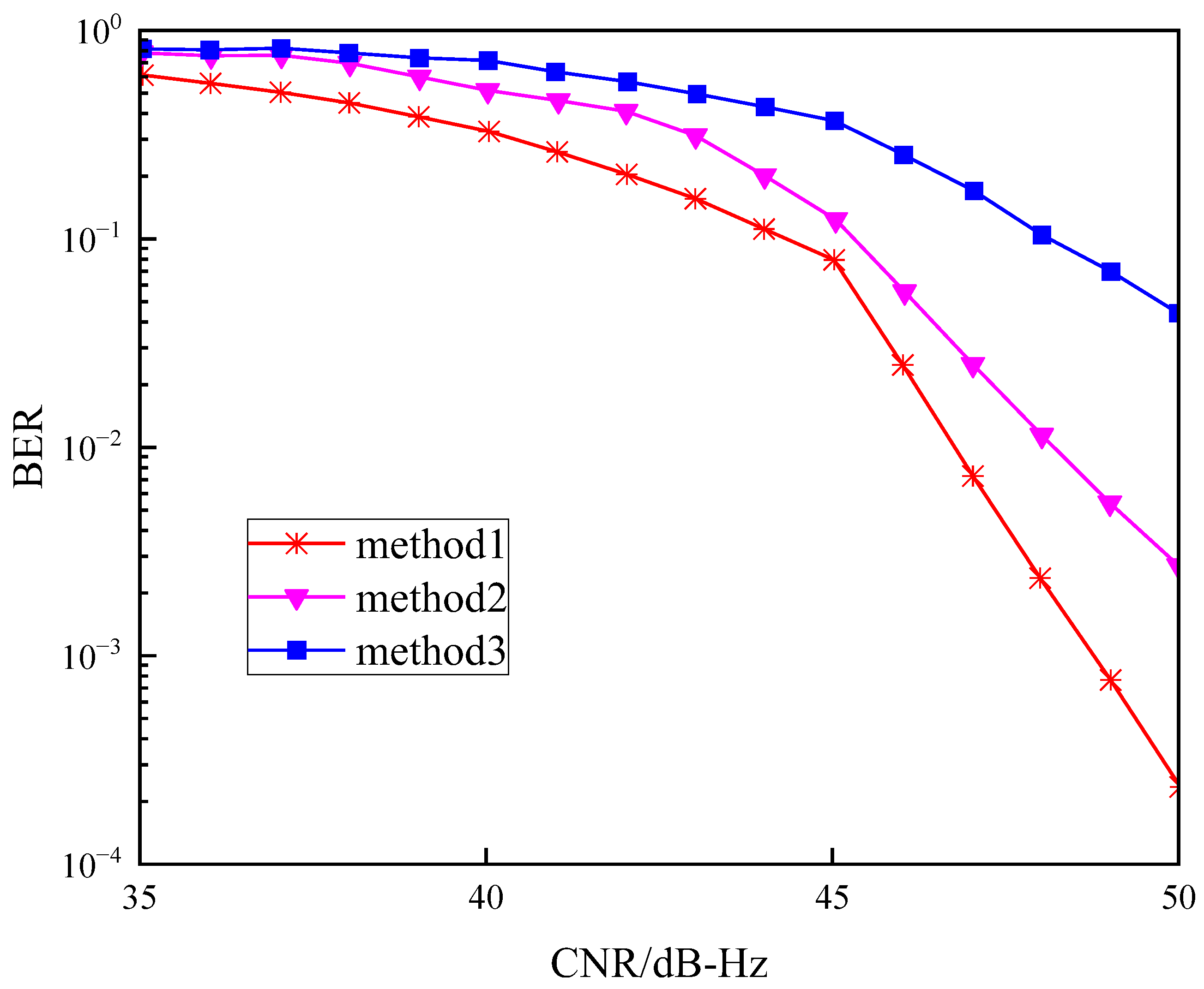
Figure 7 shows the variation of BER with CNR when Doppler is kept constant (35–50 dB-Hz) for constant Doppler. Table 3 shows the percentage BER of Method 2 and Method 3 with respect to Method 1 when Doppler is kept constant. From Figure 7, it can be seen that the BPSK-modulated signal (Method 1) has the lowest BER, the CSK (Method 3) has the highest BER, and the proposed BPSK-CSK-modulated signal is in the middle of the two. Therefore, the BPSK-CSK tracking method has a higher information transmission rate and lower BER with constant Doppler and the same CNR. The specific percentage values of BER for mode 2 and mode 3 with respect to mode 1 are given in Table 3, from which it can be seen that the BER of CSK-modulated signals is much higher than that of conventional BPSK-modulated signals, while the BER of BPSK-CSK-modulated signals is improved.
Figure 8 shows the variation of BER with CNR (35–50 dB-Hz) when . is the relative acceleration between the satellite and the receiver. Table 4 shows the percentage of BER of Method 2 and Method 3 that is higher than that of Method 1 when . From Figure 8, it can be seen that the BER of Method 2 and Method 3 is higher than that of Method 1 when . The BER when is almost the same as when Doppler is kept constant. Therefore, the BPSK-CSK tracking method has a higher message rate and lower BER when and CNR is the same. Table 3 gives the specific ratio values of the BERs of Method 2 and Method 3 with respect to Method 1, from which it can be seen that the BER of the CSK-modulated signal is much higher than that of the conventional BPSK-modulated signal when a is 10, while the BER of the BPSK-CSK-modulated signal is improved.
3.2. Tracking Error Comparison and Analysis
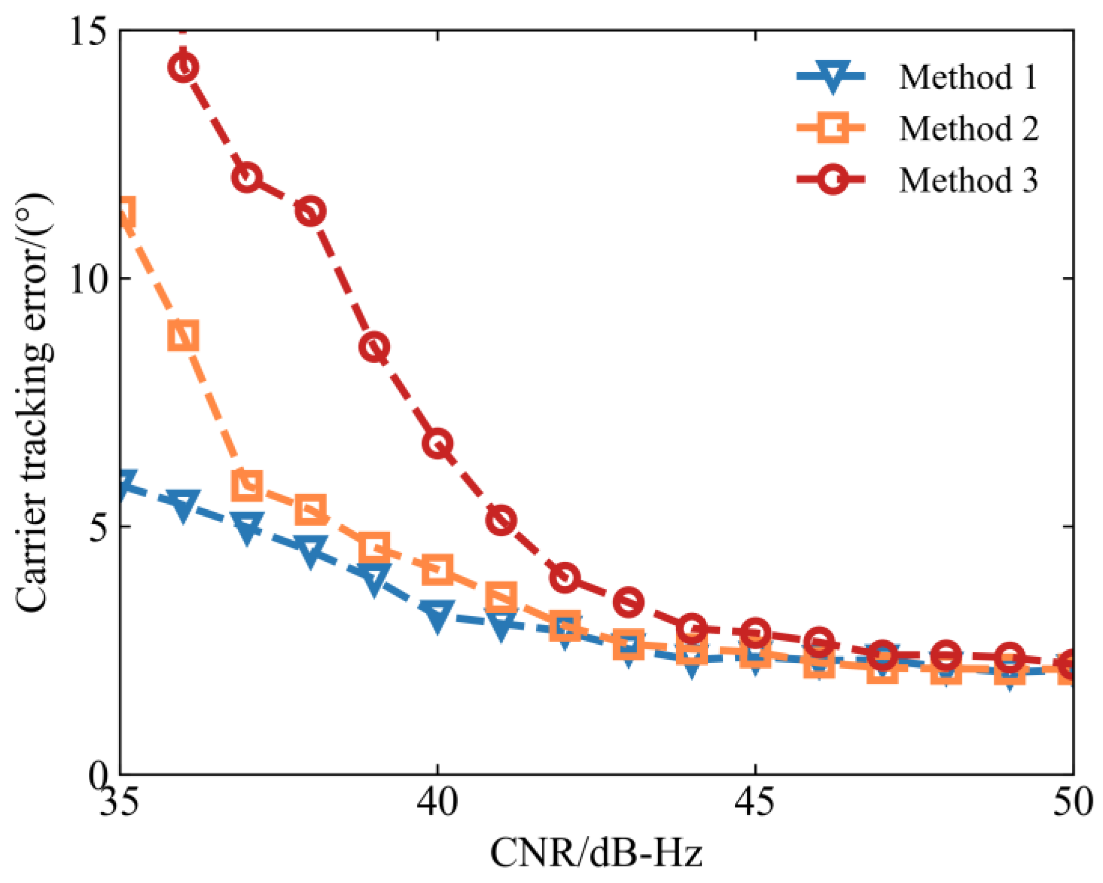
The tracking accuracy of BPSK-CSK signals is quantitatively analysed, and the code-tracking accuracy and carrier-tracking accuracy of the three tracking methods are simulated under different carrier-to-noise ratios. The results are shown in Figure 9 and Figure 10. From the point of view of code-tracking error, the tracking accuracies of the three methods are comparable when the carrier-to-noise ratio is higher than 44 dB-Hz. As the carrier-to-noise ratio decreases, the code-tracking error of this paper’s method is between Method 1 and Method 3. As far as the carrier-tracking error is concerned, the tracking accuracies of the three methods are comparable when the carrier-to-noise ratio is higher than 40 dB-Hz. As the carrier-to-noise ratio decreases, the carrier-tracking error of the methods in this paper is between Method 1 and Method 3. Therefore, the tracking method in this paper outperforms the CSK-tracking algorithm (Method 3) but is lower than the BPSK-tracking algorithm (Method 1), with a higher information transmission rate and lower tracking error, especially under low SNR conditions.
3.3. Verification Results
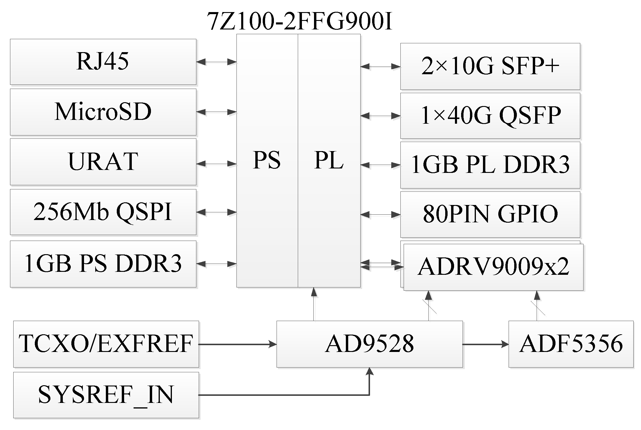
The architecture of the verification platform for the BPSK-CSK signal tracking method is shown in Figure 11, which mainly consists of the 7Z100 SOC chip and two ADRV9009 RF chips and the corresponding peripheral devices. The 7Z100 SOC chip adopts the ARM Cortex-A9 core and kintex 7 FPGA, and extends the interfaces of FMC, fibre optic, and IO through the FPGA at the PL side. The ARM at the PS side extends the interfaces of network, USB, and RS232 etc. The 7Z100 SOC chip integrates various functional modules such as high-speed data interface, digital signal processing module, memory control module etc. The ARM on the PS side extends interfaces such as network, USB, RS232, etc. The 7Z100 SOC chip integrates a variety of functional modules, such as high-speed data interfaces, digital signal processing modules, memory control modules, etc. The ADRV9009 is a dual-channel RF transmitter and receiver with an observation receiver. Operating over the frequency range of 75 MHz to 6 GHz, the device’s transmitter supports a synthesis bandwidth of up to 450 MHz. The receiver portion of the device can operate either as a dual-channel receiver supporting bandwidths up to 200 MHz or as a single-channel observation receiver supporting bandwidths up to 450 MHz. Data transmission is accomplished through eight JESD204B dedicated high-speed interface channels. There are four interface channels, each for transmitter data and main receiver/observer data.
The platform can be divided into the processor system part (PS) and programmable logic part (Programmable Logic, PL). The PS side and PL side of the platform respectively hang two pieces of the 1 GB high-speed DDR3 SDRAM chip, so that the ARM system and the FPGA system can independently process and store the data function. PS side of the FPGA expansion of the Ethernet RJ45 interface, SD card interface, UART serial interface, 256 Mb QSPI FLASH chip. PL side of the ARM expansion connected to the 10 G. The ARM expansion on the PL side is connected with the 10 G SFP+ module, 40 GB QSFP interface, 80-pin GPIO, and two ADRV9009 RF chips. A 256 Mb QSPI FLASH is used for the static storage of ZYNQ’s operating system, file system, and user data. The clock generator AD9528 accesses the SYSREF signal and connects to the TXCO/EXFREF interface, which is used to synchronise multiple devices such as ADRV9009 and ADF5356.
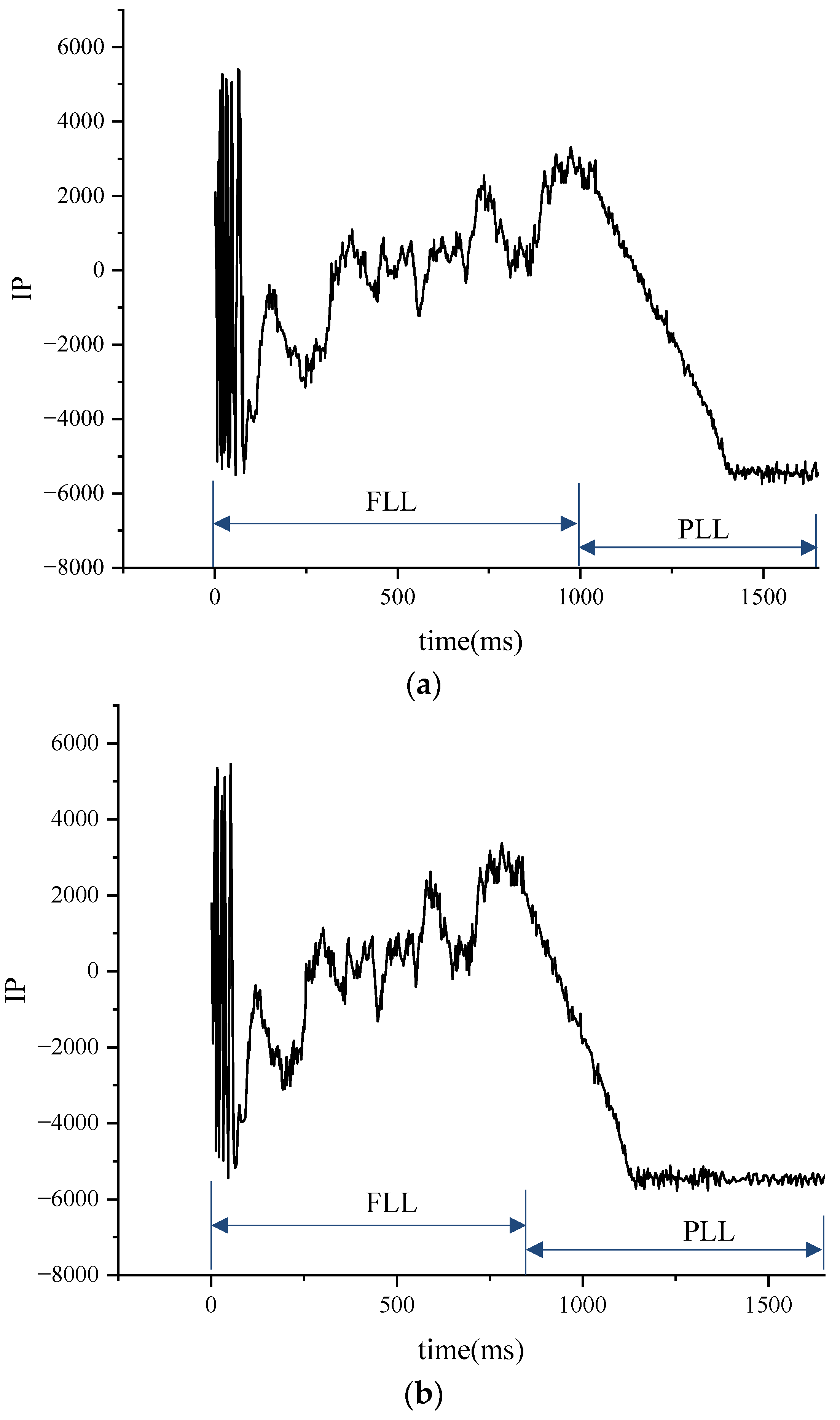
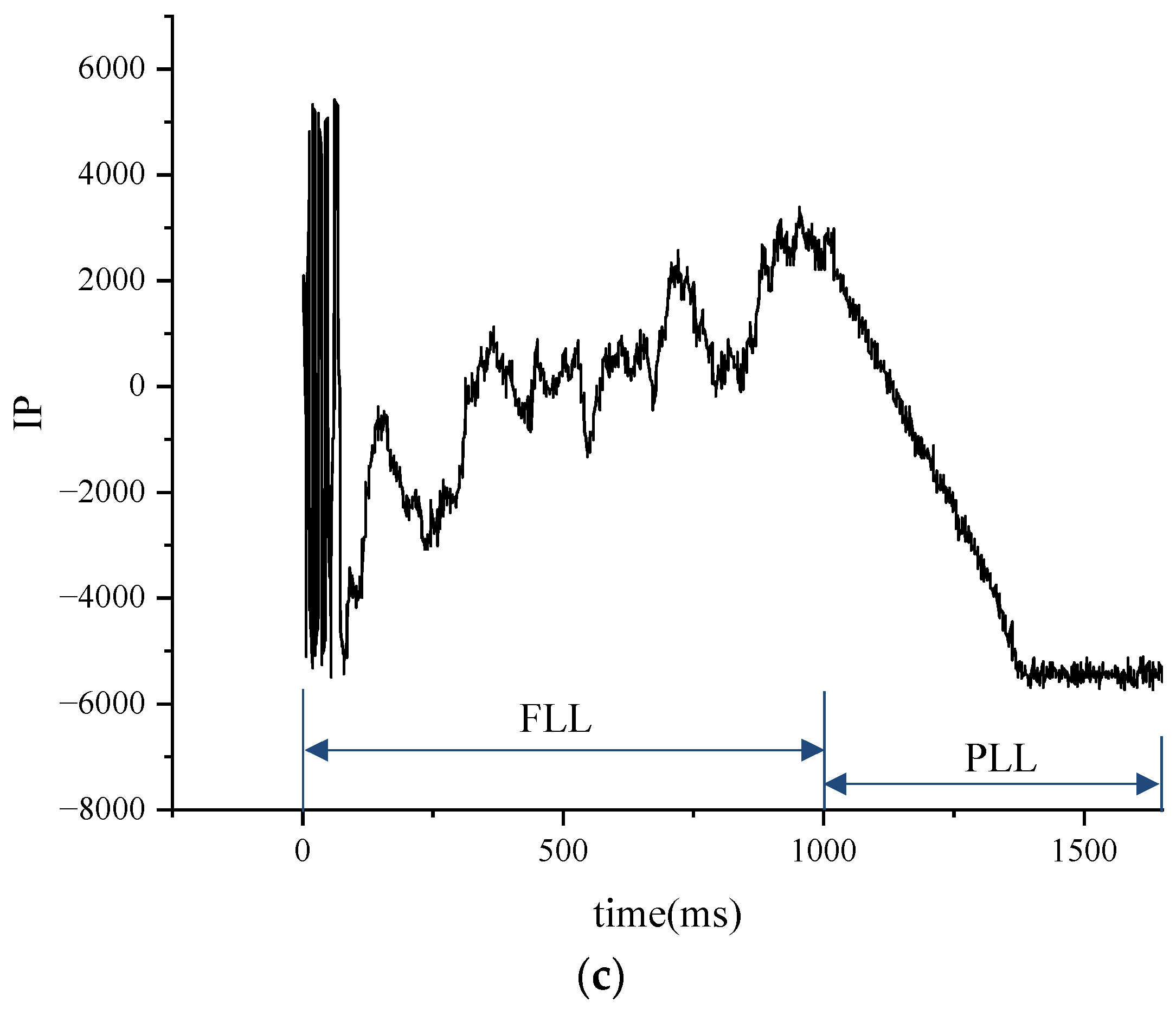
In the experiments using the 7Z100 SOC chip and the ADRV9009 RF chip for signal tracking, the Doppler value was 1000 Hz, the sampling time was 10 s, and the parameters of the carrier- and code-tracking loops are shown in Table 1 and Table 2 in the previous section. We tested three different methods, the output data for the output tracking results, and recorded their respective signal convergence processes using Origin. The curves of the i-branch integral values over time for the three methods are shown in Figure 12, and the experimental results demonstrate the differences in signal convergence among the three methods.
By comparing the convergence processes of the three methods, we find that the tracking method proposed in this paper performs well in terms of convergence time. Compared with Methods 1 and 3, the method in this paper is able to converge to the steady state more quickly, showing its superior convergence performance. This fast convergence property makes this paper’s method have higher real-time and response speeds in practical applications, which can better meet the demand for fast tracking.
Compared with Methods 1 and 3, the method in this paper exhibits good signal convergence characteristics and demodulation performance in addition to a fast convergence time. During the signal convergence process, the method in this paper is able to track signal changes stably and maintain high demodulation accuracy. This means that in the case of poor signal quality or interference, the method in this paper can still effectively extract useful information and ensure the reliability and stability of communication.
4. Discussion
A high-precision service has gradually become the standard of GNSS, and high information rate has also become the design requirement of future satellite navigation signals. CSK-modulated signals, which have the advantage of a high information rate, have attracted a lot of attention from scholars, but its BER is higher than that of BPSK-modulated signals and the number of related signals required is more than that of BPSK, whereas BPSK-modulated signals have a low BER, but their low information transmission rate is not enough to meet the high-precision service of GNSS. In addition, in complex urban environments, CSK modulation will also provide better performance than BPSK, which is an orthogonal M-propagation modulation that allows for non-coherent demodulation. Non-coherent modulation allows the demodulation of CSK signals in harsh environments such as urban or indoor environments, whereas for BPSK signals, demodulation is not possible unless the PLL is locked.
The BPSK-CSK signal tracking method proposed in this article combines the high information transmission rate of the CSK modulation signal and the low BER of the BPSK signal, and gives a compromise solution, which provides a solid foundation for a high-precision GNSS service. CSK modulation has the advantages of a high transmission rate, flexible bit rate, and non-coherent demodulation, but there are the advantages of the difficult-to-achieve synchronisation process, and the complexity of the receiver is high. The number of correlators is much larger than that of BPSK and so on. Considering the above problems, this paper uses it in the design of GNSS signals. Considering the above problems, it is not feasible to use CSK modulation to completely replace BPSK in a GNSS system, but CSK modulation can be gradually introduced into GNSS systems to achieve the purpose of improving the positioning accuracy and quality of service, and optimising the system performance.
Author Contributions
Y.C.: conceptualization, methodology, software, investigation, formal analysis, writing—original draft; J.C.: data curation, writing—original draft; X.L.: visualization, investigation; X.B.: resources, supervision; Z.N.: conceptualization, resources, supervision, writing—review and editing. All authors have read and agreed to the published version of the manuscript.
Funding
This research received no funding.
Data Availability Statement
The datasets used in this study are managed by the Beijing Research Institute of Telemetry, Beijing, China and can be available on request from the corresponding author.
Conflicts of Interest
The authors declare no conflict of interest.
References
- Fu, Y.; Tang, Z.; Wei, J.; Lin, M. Analysis of high-rate GNSS modulation and coding scheme based on CSK and non-binary LDPC. In Proceedings of the 12th Annual China Satellite Navigation Conference, Nanchang, China, 26–28 May 2021; pp. 1–7. [Google Scholar]
- Lopacinski, L.; Maletic, N.; Kraemer, R.; Hasani, A.; Gutiérrez, J.; Krstic, M.; Grass, E. Amplitude- and phase-modulated PSSS for wide bandwidth mixed analog-digital baseband processors in THz communication. In Proceedings of the 2023 IEEE 97th Vehicular Technology Conference (VTC2023-Spring), Florence, Italy, 20–23 June 2023; Volume 1, No. 2. pp. 1–5. [Google Scholar]
- IS-QZSS-L6-005; Quasi-Zenith Satellite System Interface Specification Centimeter Level Augmentation Service. Cabinet Office: Tokyo, Japan, 2022.
- Yan, T.; Wang, Y.; Li, T.; Tian, Y.; Qu, B.; Bian, L. MCSK Signal for LEO Satellite Constellation Based Navigation Augmentation System. In Proceedings of the China Satellite Navigation Conference (CSNC 2024), Jinan, China, 22–24 May 2024. [Google Scholar]
- Guan, L.; Xu, Z.; Tian, L.; Shi, C. Analysis and Simulation of Interference Effects on CSK Modulation Systems. In Proceedings of the 2022 15th International Congress on Image and Signal Processing, BioMedical Engineering and Informatics (CISP-BMEI), Beijing, China, 5–7 November 2022; pp. 1–7. [Google Scholar]
- Chen, X.; Luo, R.; Liu, T.; Yuan, H.; Wu, H. Satellite navigation signal authentication in GNSS: A survey on technology evolution, status, and perspective for BDS. Remote Sens. 2023, 15, 1462. [Google Scholar] [CrossRef]
- Ma, S.; Li, X.; Zou, D. A CCSK based navigation and communication integrated satellite signal. In Proceedings of the IEEE International Wireless Communications and Mobile Computing, Harbin, China, 28 June–2 July 2021; pp. 1079–1082. [Google Scholar]
- Meng, Y.; Yan, T.; Bian, L.; Wang, Y.; Tian, Y. LEO broadband satellite constellations based global navigation augmentation: Opportunity and challenge. Navig. Position Timing 2022, 9, 12–24. [Google Scholar]
- Colburn, R. Global positioning system status and modernization. In Proceedings of the 33rd International Technical Meeting of the Satellite Division of the Institute of Navigation (ION GNSS+ 2020), Online, 22–25 September 2020; The Institute of Navigation: Manassas, VA, USA, 2020; pp. 929–937. [Google Scholar]
- Reid, T.G.; Chan, B.; Goel, A.; Gunning, K.; Manning, B.; Martin, J.; Neish, A.; Perkins, A.; Tarantino, P. Satellite navigation for the age of autonomy. Proceedings of 2020 IEEE/ION Position, Location and Navigation Symposium (PLANS), Portland, OR, USA, 20–23 April 2020; IEEE: Piscataway, NJ, USA, 2020; pp. 342–352. [Google Scholar]
- Behera, P.; Siddique, A.; Delwar, T.S.; Ryu, J.-Y. Performance analysis of FIR based communication in multi user scenario using CSK. Opt. Quantum Electron. 2021, 53, 486. [Google Scholar] [CrossRef]
- Chatre, E.; Benedicto, J. Galileo programme update. In Proceedings of the 33rd International Technical Meeting of the Satellite Division of the Institute of Navigation (ION GNSS+ 2020), Online, 22–25 September 2020; The Institute of Navigation: Manassas, VA, USA, 2020; pp. 950–977. [Google Scholar]
- Shen, J.; Geng, C. Update on the beidou navigation satellite system (bds). In Proceedings of the 33rd International Technical Meeting of the Satellite Division of the Institute of Navigation (ION GNSS+ 2020), Online, 22–25 September 2020; The Institute of Navigation: Manassas, VA, USA, 2020; pp. 978–1015. [Google Scholar]
- Liu, X.; Ba, X.; Jie, C.; Li, M.; Qi, X. Algorithm for non-orthogonal code shift keying and code index modulation. Syst. Eng. Electron. 2021, 43, 232–236. [Google Scholar]
- Pena, A.G.; Julien, O.; Anghileri, M. Multipurpose TDM component for GNSS. In Proceedings of the 31th International Technical Meetings of the ION Satellite Division (ION GNSS+ 2018), Miami, FL, USA, 24–28 September 2018; pp. 943–962. [Google Scholar]
- Zou, D.; Li, X.; Ma, R. A signal optimization strategy for next generation navigation and communication integration applications. Phys. Commun. 2022, 50, 101510. [Google Scholar] [CrossRef]
- Delwar, T.S.; Siddique, A.; Biswal, M.R.; Rashed, A.N.Z.; Jana, A.; Ryu, J.Y. Novel Multi-user MC-CSK Modulation Technique in Visible Light Communication. Opt. Quantum Electron. 2021, 53, 196. [Google Scholar] [CrossRef]
- Rui, X.; Ruan, H. Low-complexity iterative detection algorithm in LDPC-CSK scheme for high-speed GNSS. In Proceedings of the 9th International Conference on Networks, Communication and Computing, (ICNCC 2020), Online, 18–20 December 2020. [Google Scholar]
- Komuro, N.; Habuchi, H. Impact of systematically constructed nonorthogonal code shift keying for optical code division multiple access. OSA Contin. 2023, 2, 131–142. [Google Scholar] [CrossRef]
- Jing, L.; He, C.; Wang, H.; Zhang, Q.; Yin, H. A New IDMA System Based on CSK Modulation for Multiuser Underwater Acoustic Communications. IEEE Trans. Veh. Technol. 2020, 69, 3080–3092. [Google Scholar] [CrossRef]
- Koshimoto, M.; Kozawa, Y.; Habuchi, H. Theoretical analysis of underwater simultaneous light Information and power transfer using inverted N parallel code shift keying with power splitting receiver. In Proceedings of the 2023 IEEE International Symposium on Circuits and Systems (ISCAS), Monterey, CA, USA, 21–25 May 2023. [Google Scholar]
- Yan, T.; Wang, Y.; Liu, X.; Bian, L.; Meng, Y. Research on MPSK Modulation Based GNSS Signals with High Data Rate. In Proceedings of the 2020 China Satellite Navigation Conference, Chengdu, China, 22–25 November 2020; Springer: Singapore, 2020; pp. 474–484. [Google Scholar]
- Ortega, L.; Vilà-Valls, J.; Poulliat, C.; Closas, P. GNSS Data Demodulation over Fading Environments: Antipodal and M-ary CSK Modulations. IET Radar Sonar Navig. 2021, 15, 113–127. [Google Scholar] [CrossRef]
- Cho, H.; Song, H.-Y.; Ahn, J.M.; Lim, D.W. Some New RS-coded Orthogonal Modulation Schemes for Future GNSS. ICT Express 2021, 7, 530–534. [Google Scholar] [CrossRef]
- Chauvat, R.; Garcia-Pena, A.; Paonni, M. On efficient and low-complexity decoding of binary LDPC-coded CSK signals for GNSS links with increased data rates. Proceedings of 2020 IEEE/ION Position, Location and Navigation Symposium, Portland, OR, USA, 20–23 April 2020. [Google Scholar]
- Chen, Y.; Wang, D.; Chen, S.; Ma, W.; Li, D.; Dong, Q. Research on receiving method of code shift keying (CSK) signal. Proceedings of 11th China Satellite Navigation Conference (CSNC), Chengdu, China, 22–25 November 2020; pp. 298–309. [Google Scholar]
- Yan, T.; Wang, Y.; Li, T.; Tian, Y.; Bian, L.; Meng, Y. Low complexity acquisition and tracking methods for CSK modulated signals. In Proceedings of the China Satellite Navigation Conference (CSNC 2021) Proceedings, Nanchang, China, 22–25 May 2021; Springer: Berlin/Heidelberg, Germany, 2021; Volume III, pp. 193–202. [Google Scholar]
- Yan, T.; Tian, Y.; Li, T.; Wang, G.; Wang, Y.; Zhou, Q.; Bian, L. Tracking method for code shift keying(CSK) modulated signal. Chin. Space Sci. Technol. 2023, 43, 117–127. [Google Scholar]
- Li, Y.; Zhou, G.; Xiao, L.; Chen, H. An Efficient Demodulation Algorithm for CSK Modulated Signals Based on Block FFT. Radio Eng. 2023, 53, 1321–1327. [Google Scholar]
- Li, Y.; Zhou, G.; Xiao, L.; Chen, H. An efficient demodulation algorithm for CSK modulated signals based on partial output FFT. Gnss World China 2022, 47, 73–78. [Google Scholar]
- He, X.; Liu, C.; Wang, W.; Li, J.; Liu, X.; Yang, Y.; Ba, X.; Chen, J. The design of Galileo E6B/C receiver. Appl. Electron. Tech. 2020, 46, 8–11+17. [Google Scholar]
Figure 1.
CSK modulation process.

Figure 2.
FFT-based CSK demodulation schematic.
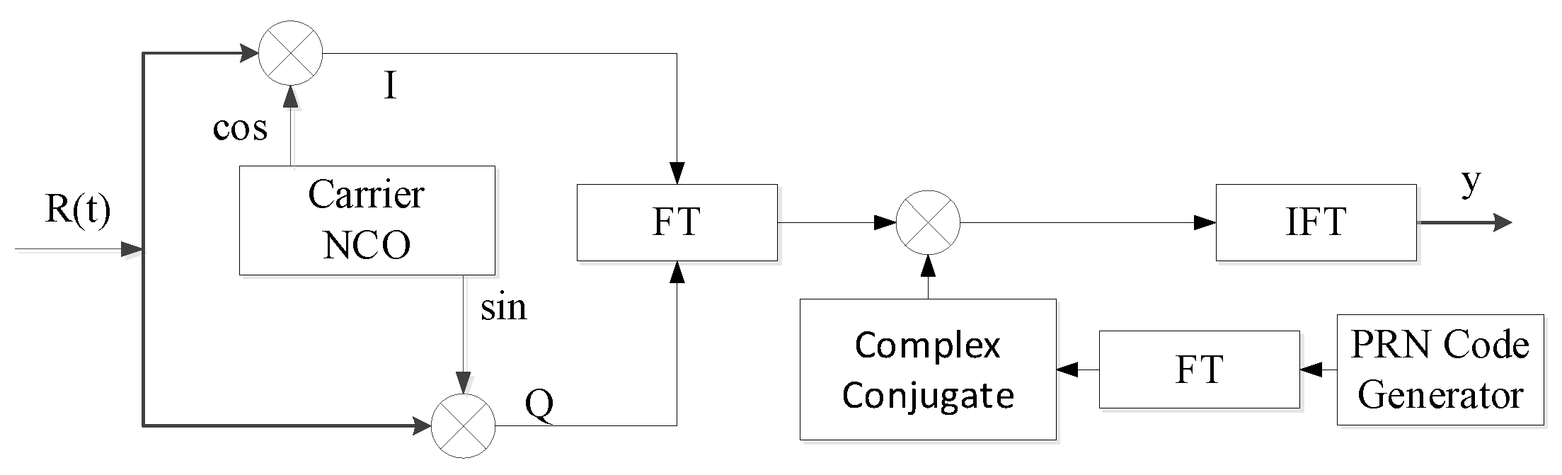
Figure 3.
BPSK-CSK time division multiplexing diagram.

Figure 4.
Flowchart of the BPSK-CSK tracking method.
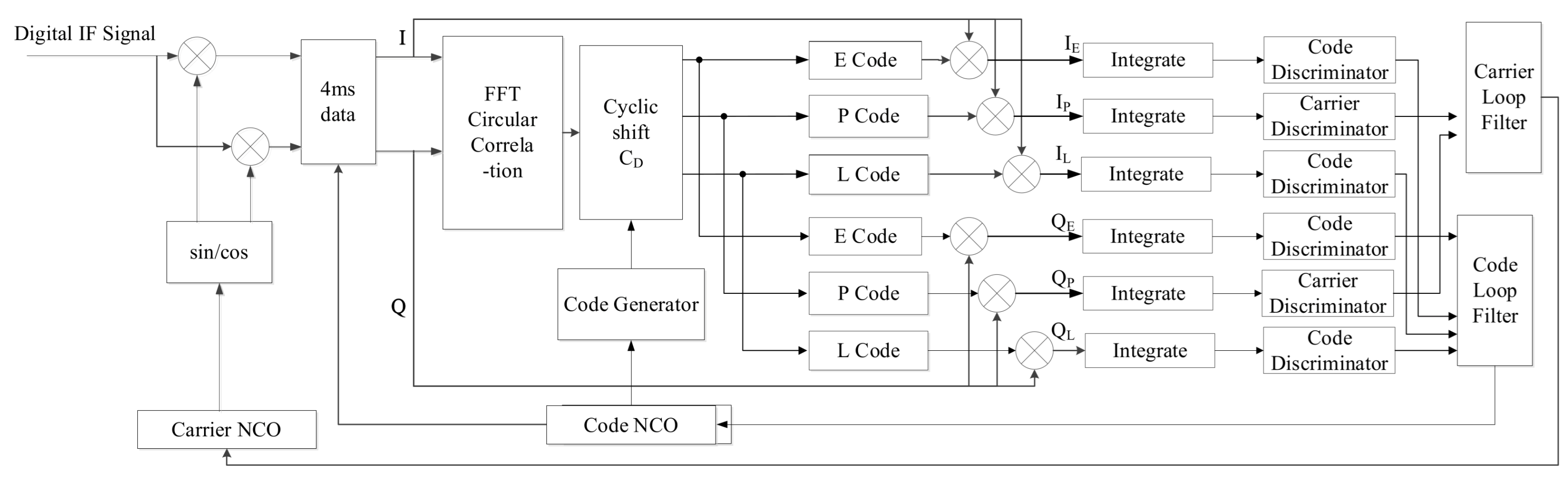
Figure 5.
Carrier-tracking loop.

Figure 6.
Code-tracking loop.
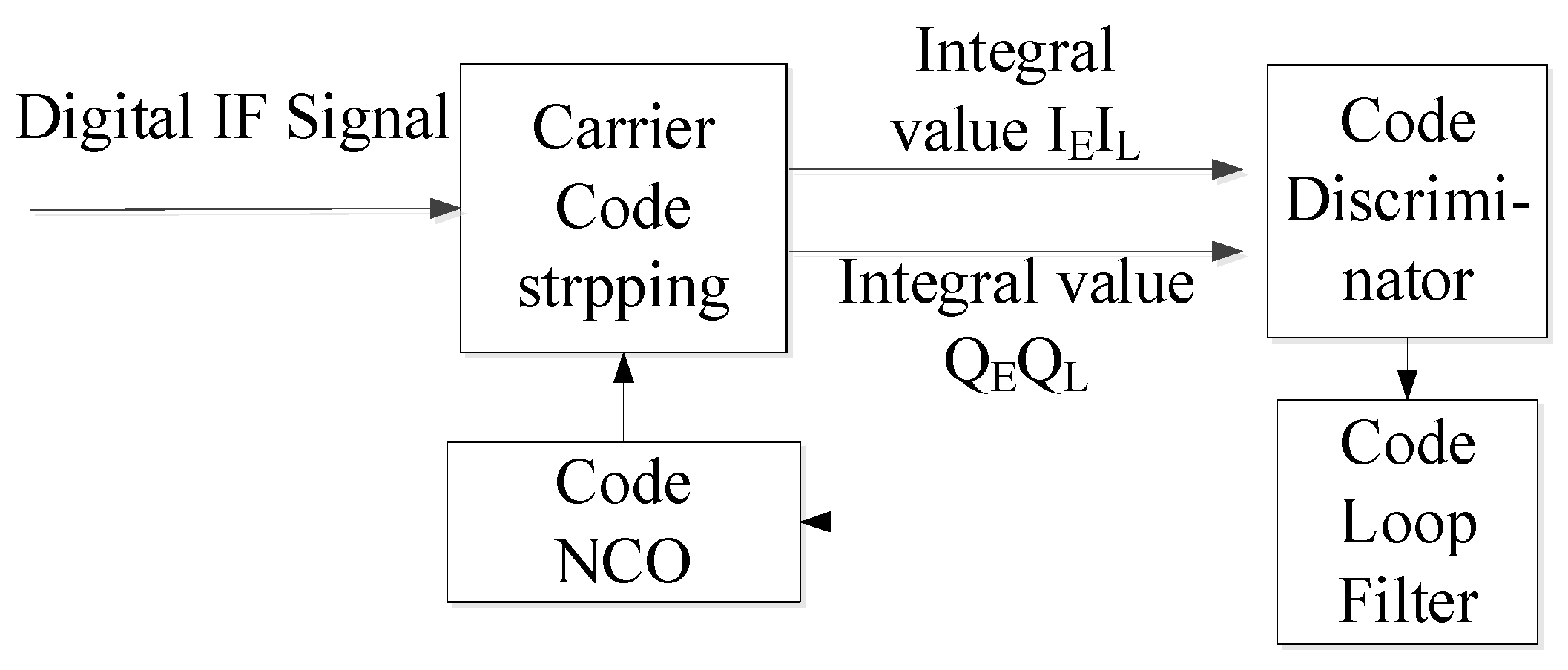
Figure 7.
BER varies with CNR when Doppler is constant.
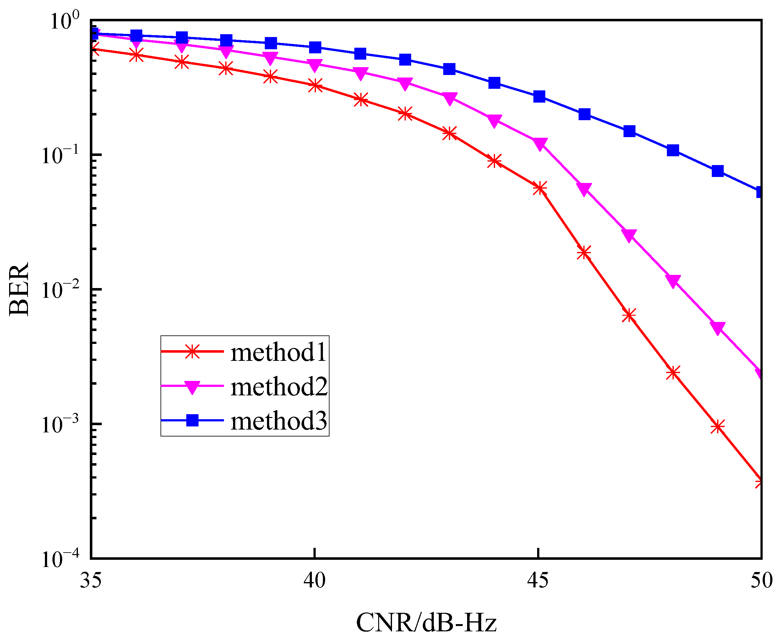
Figure 8.
BER varies with CNR when .

Figure 9.
Carrier-tracking error.

Figure 10.
Code-tracking error.
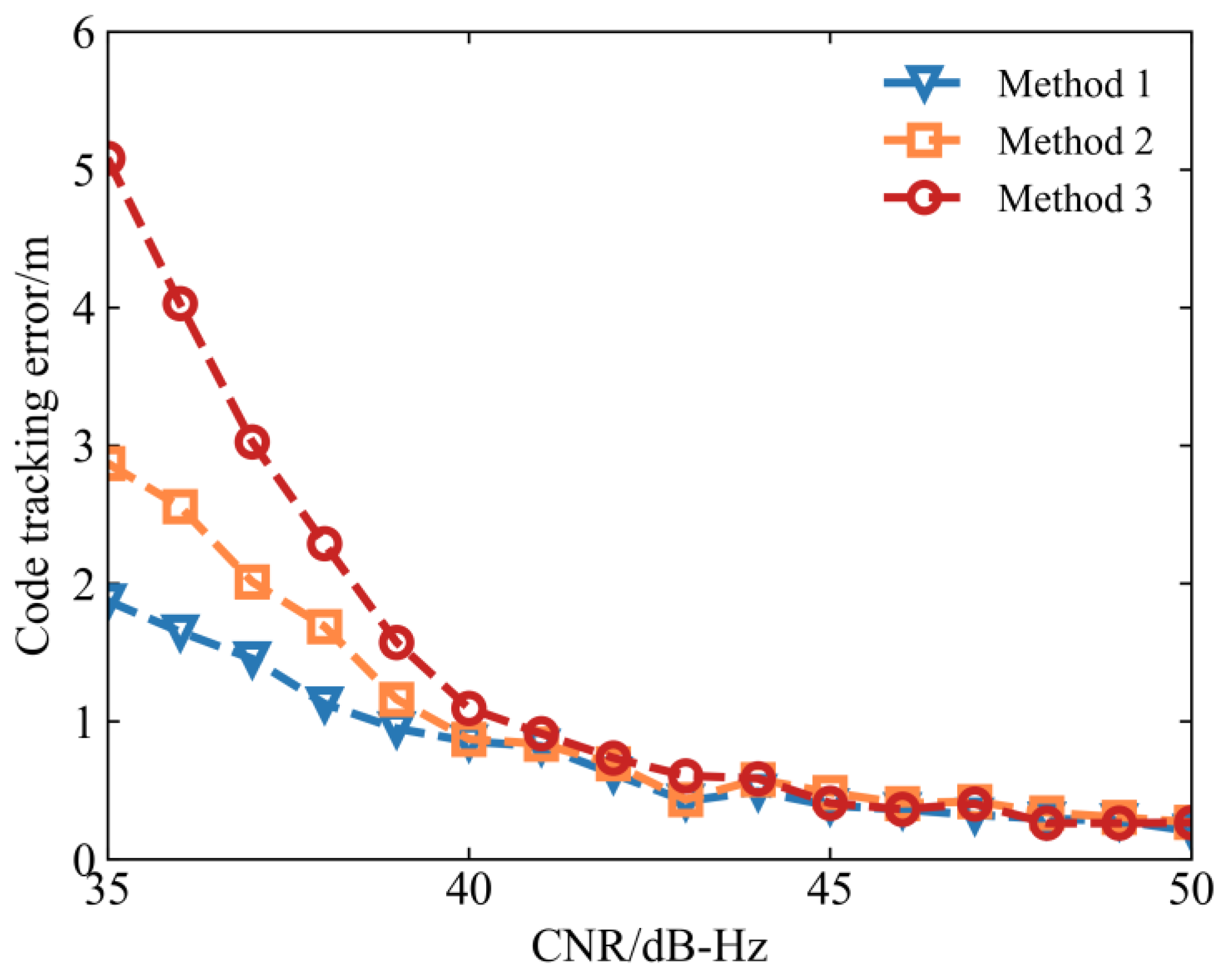
Figure 11.
BPSK-CSK signal tracking program verification platform.

Figure 12.
Tracking loop handling in three scenarios: (a) is Tracking Loop Processing for Method 1; (b) is Tracking Loop Processing for Method 2; (c) is Tracking Loop Processing for Method 3.
Figure 12.
Tracking loop handling in three scenarios: (a) is Tracking Loop Processing for Method 1; (b) is Tracking Loop Processing for Method 2; (c) is Tracking Loop Processing for Method 3.


Table 1.
Carrier-tracking loop parameters.
| Coherent Integration Time/ms | Non-Coherent Integration Time/ms | Traction Range/Hz | Loop Bandwidth/Hz |
|---|---|---|---|
| 4 | 1 | ±62.5 | 20 |
Table 2.
Code-tracking loop parameters.
| Coherent Integration Time/ms | Non-Coherent Integration Time/ms | Code Spacing of E,L/Code-Chip | Loop Bandwidth/Hz |
|---|---|---|---|
| 4 | 1 | 1 | 2 |
Table 3.
BER proportion of Method 2 and 3 higher than Method 1 when Doppler is constant.
| CNR/(dB-Hz) | Method 3 Higher than Method 1/% | Method 2 Higher than Method 1/% |
|---|---|---|
| 36 | 36.00 | 18.42 |
| 37 | 35.41 | 18.99 |
| 38 | 34.79 | 19.56 |
| 39 | 34.19 | 20.12 |
| 40 | 32.82 | 16.24 |
| 41 | 31.61 | 12.39 |
| 42 | 30.47 | 8.53 |
| 43 | 29.24 | 4.67 |
| 44 | 25.43 | 3.85 |
| 45 | 21.12 | 3.11 |
| 46 | 17.56 | 2.31 |
| 47 | 13.31 | 1.52 |
| 48 | 10.54 | 1.15 |
| 49 | 7.27 | 0.78 |
| 50 | 4.15 | 0.41 |
Table 4.
BER proportion of Method 2 and 3 higher than Method 1 when .
| CNR/(dB-Hz) | Method 3 Higher than Method 1/% | Method 2 Higher than Method 1/% |
|---|---|---|
| 36 | 27.72 | 16.38 |
| 37 | 28.67 | 15.44 |
| 38 | 29.59 | 14.49 |
| 39 | 30.63 | 13.54 |
| 40 | 28.49 | 11.88 |
| 41 | 26.27 | 10.23 |
| 42 | 24.09 | 8.57 |
| 43 | 21.92 | 6.91 |
| 44 | 19.55 | 5.53 |
| 45 | 17.28 | 4.16 |
| 46 | 14.92 | 2.79 |
| 47 | 12.59 | 1.42 |
| 48 | 10.12 | 1.12 |
| 49 | 7.65 | 0.81 |
| 50 | 5.18 | 0.51 |
Disclaimer/Publisher’s Note: The statements, opinions and data contained in all publications are solely those of the individual author(s) and contributor(s) and not of MDPI and/or the editor(s). MDPI and/or the editor(s) disclaim responsibility for any injury to people or property resulting from any ideas, methods, instructions or products referred to in the content. |
© 2024 by the authors. Licensee MDPI, Basel, Switzerland. This article is an open access article distributed under the terms and conditions of the Creative Commons Attribution (CC BY) license (https://creativecommons.org/licenses/by/4.0/).
Share and Cite
MDPI and ACS Style
Chen, Y.; Cheng, J.; Li, X.; Bai, X.; Nie, Z. Research on Tracking Technique Based on BPSK-CSK Signals. Electronics 2024, 13, 1517. https://doi.org/10.3390/electronics13081517
AMA Style
Chen Y, Cheng J, Li X, Bai X, Nie Z. Research on Tracking Technique Based on BPSK-CSK Signals. Electronics. 2024; 13(8):1517. https://doi.org/10.3390/electronics13081517
Chicago/Turabian StyleChen, Yuxin, Jie Cheng, Xiaodong Li, Xue Bai, and Zhixi Nie. 2024. "Research on Tracking Technique Based on BPSK-CSK Signals" Electronics 13, no. 8: 1517. https://doi.org/10.3390/electronics13081517
Note that from the first issue of 2016, this journal uses article numbers instead of page numbers. See further details here.