Article

Highly Fault-Tolerant Systolic-Array-Based Matrix Multiplication

Department of Electronic Engineering, Chung Yuan Christian University, Taoyuan 320314, Taiwan
*
Author to whom correspondence should be addressed.
Electronics 2024, 13(9), 1780; https://doi.org/10.3390/electronics13091780
Submission received: 30 March 2024 / Revised: 21 April 2024 / Accepted: 1 May 2024 / Published: 5 May 2024
(This article belongs to the Special Issue System-on-Chip (SoC) and Field-Programmable Gate Array (FPGA) Design)

Abstract

:
Matrix multiplication plays a crucial role in various engineering and scientific applications. Cannon’s algorithm, executed within two-dimensional systolic arrays, significantly enhances computational efficiency through parallel processing. However, as the matrix size increases, reliability issues become more prominent. Although the previous work has proposed a fault-tolerant mechanism, it is only suitable for scenarios with a limited number of faulty processing elements (PEs). This paper introduces a pair-matching mechanism, assigning a fault-free PE as a proxy for each faulty PE to execute its tasks. Our fault-tolerant mechanism comprises two stages: in the first stage, each fault-free PE completes its designated computations; in the second stage, computations intended for each faulty PE are executed by its assigned fault-free PE proxy. The experimental results demonstrate that compared to the previous work, our approach not only significantly improves the fault tolerance of systolic arrays (applicable to scenarios with a higher number of faulty PEs) but also reduces circuit areas. Therefore, the proposed approach proves effective in practical applications.

1. Introduction

Matrix multiplication plays a vital role in diverse engineering and scientific applications. For example, in convolutional neural networks, convolutions can also be depicted as matrix multiplications. To fulfill the needs of high-speed processing, minimizing the computation time for matrix multiplication is crucial. Therefore, several algorithms have been introduced in the past to accelerate matrix multiplications, such as Cannon’s algorithm [1] and Winograd’s algorithm [2].
A systolic array [3,4,5,6,7] serves as a general matrix multiplication accelerator, achieving matrix multiplication in a regular and parallel manner via data transmission between processing elements (PEs). Each PE is primarily responsible for executing multiply–accumulate computations [8,9]. Cannon’s algorithm can also be implemented through a systolic array. Taking a 4 × 4 systolic array as an example, if matrix operations are performed using the traditional algorithm, it would require 10 clock cycles, whereas utilizing Cannon’s algorithm for matrix operations would only require four clock cycles.
Although a systolic array reduces computation time through parallel processing, it also increases the likelihood of hardware failures. Note that these hardware failures are caused by latent manufacturing defects [10,11] or circuit aging effects [12,13], potentially resulting in functional errors. We can employ post-manufacturing testing mechanisms [14,15] to identify latent manufacturing defects. Additionally, run-time detection mechanisms [16,17] can be used to identify the effects of circuit aging.
As the size of the matrix increases, the probability of hardware failures also increases. Therefore, besides identifying hardware failures, it is imperative to incorporate fault-tolerance mechanisms to enhance the reliability of the systolic array for matrix multiplication. Especially in applications such as healthcare, aviation, autonomous driving, underwater communication, etc., where system reliability is crucial, fault-tolerance mechanisms are indispensable [18,19,20].
The research area of fault tolerance has a rich history, starting with early work on addressing permanent faults in memory systems using error-correcting codes [21,22] or redundant memories (such as spare rows and columns) [23,24], as well as triple modular redundancy strategies [25,26], to mitigate faults in computational logic. Nevertheless, these fault-tolerant design methodologies do not directly extend to systolic arrays.
Kim and Reddy [27] delved into fault-tolerant systolic array design, focusing on the notion of treating a faulty systolic array as a simplified version with fewer rows and columns. Stojanovic et al. [28] achieved fault tolerance through triplicated computations and majority voting, offering two hardware solutions for the voting process. Milovanovic et al. [29] introduced a systematic approach to designing fault-tolerant systolic arrays with orthogonal interconnects and unidirectional data flow for matrix multiplication. It is important to note that all of these methods [27,28,29] require the inclusion of redundant PEs.
Jan and Huang [30] discuss the fault-tolerant design of a systolic array executing Cannon’s algorithm [1] for matrix multiplications. Their basic idea involves assigning the task of a faulty PE to a fault-free PE for execution. Therefore, their approach does not require redundant PEs. In [30], they propose a mapping algorithm to implement both a twisted column scheme and a column replacement scheme. If the number of faulty PEs is small, their method can achieve very high fault tolerance.
However, the approach proposed by Jan and Huang [30] cannot be applied when there is a large number of faulty PEs. The main reason is that their method requires the existence of at least one fault-free column (even in the form of a twisted column). However, if there are many faulty PEs, it may not be possible to find a fault-free column (even in the form of a twisted column). For certain application domains, such as space or deep sea exploration, it is difficult to repair even if many PEs fail. Therefore, we need to develop design methods with higher fault tolerance to enhance the lifespan of systolic arrays.
In this paper, we propose a highly fault-tolerant approach for a systolic array executing Cannon’s algorithm for matrix multiplication. We observe that the main limitation of the previous work [30] lies in the necessity to find a fault-free column (even in the form of a twisted column). Consequently, the previous work is only suitable for situations where the number of faulty PEs is relatively low. In contrast to the previous approach [30], our method does not require the existence of a fault-free column, thus enabling its application in scenarios with a higher number of faulty PEs.
Our fundamental idea is to pair each faulty PE with a corresponding fault-free PE to act as its proxy. Therefore, our matrix multiplication computation is divided into two primary stages: in the first stage, each fault-free PE completes the computations that it should perform. In the second stage, the computations that each faulty PE should carry out are completed by the fault-free PE for which it is acting as a proxy. Since the data required by each fault-free PE are directly transmitted by the controller, the proposed approach does not require a fault-free column.
This paper introduces two pair-matching schemes: row-based pair-matching and column-based pair-matching. Based on these schemes, we propose two pair-matching algorithms: one-dimensional pair-matching (i.e., utilizing only row-based pair-matching) and two-dimensional pair-matching (i.e., utilizing both row-based pair-matching and column-based pair-matching). Employing two-dimensional pair-matching offers higher fault tolerance compared to using one-dimensional pair-matching, but it also increases the controller area.
We used the TSMC 40nm cell library to implement the proposed approach. The experiment results demonstrate that compared to the previous work [30], the proposed approach (whether utilizing one-dimensional pair-matching or two-dimensional pair-matching) not only enhances the fault tolerance but also reduces the circuit area. This is attributed to the fact that the previous work [30] requires consideration of the twisted column scheme, which not only complicates the data path design for each PE but also complicates the controller design for the systolic array. Therefore, the proposed pair-matching method can simplify the design of both the controller and PEs.
The primary contributions of our work are elaborated below.
  • We introduce a fault-tolerant approach using pair-matching, with  the analysis results showcasing a notable enhancement in the fault-tolerance capabilities compared to those in the previous work [30].
  • We implemented the pair-matching approach in circuitry, with the experimental results indicating reduced areas for both the controller and PEs in comparison to those in the previous work [30].
Note that, in recent years, there have also been some studies [31,32,33,34] exploring fault-tolerant designs for systolic-array-based deep neural network (DNN) accelerators. Due to the inherent fault-tolerant nature of artificial intelligence applications, these studies’ fault-tolerant designs may allow for some errors. Unlike these studies [31,32,33,34], we must ensure the correctness of the matrix multiplication results. Therefore, the fault-tolerance issues that we investigate in matrix multiplication differ fundamentally from those addressed in the literature on the fault tolerance of DNN accelerators.
The remainder of this paper is structured as follows. Section 2 offers background materials. Section 3 introduces the proposed fault-tolerance approach, encompassing one-dimensional pair-matching and two-dimensional pair-matching. Section 4 showcases our experimental results. Lastly, concluding remarks are provided in Section 5.

2. Preliminaries

In this section, we present background materials. Section 2.1 introduces the systolic array architecture. Section 2.2 presents Cannon’s algorithm. Section 2.3 discusses the fault-tolerant mechanism proposed by Jan and Huang [30].

2.1. The Systolic Array Architecture

Suppose that n × n matrices A and B are represented as Equations (1) and (2), respectively:
A = A 0 , 0 A 0 , n 1 A n 1 , 0 A n 1 , n 1
B = B 0 , 0 B 0 , n 1 B n 1 , 0 B n 1 , n 1
Then, the n × n matrix multiplication A × B can be expressed as Equation (3):
C i , j = k = 0 n 1 A i , k × B k , j
A systolic array functions as a versatile accelerator for matrix multiplication, accomplishing the task in a structured and parallel fashion through data exchange among PEs. Each PE is primarily tasked with performing multiply–accumulate computations. Additionally, each PE also requires interconnection circuits for data transmission. Taking a 4 × 4 systolic array as an example, with each clock cycle, matrix A moves one step to the right, and matrix B moves one step downward, as shown in Figure 1. After 10 clock cycles, matrix multiplication can be completed.

2.2. Cannon’s Algorithm

Cannon’s algorithm can be used to accelerate matrix multiplications. It primarily involves three steps:
  • Initial alignment: The rows of matrix A are shifted to the left by i steps ( 0 i n ), with the 0-th row shifted 0 steps, the 1-st row shifted 1 step, and so forth; the columns of matrix B are shifted upwards by j steps ( 0 j n 1 ), with the 0-th column shifted 0 step, the 1-st column shifted 1 step, and so forth.
  • Multiplication and accumulation: The two aligned matrices are overlapped, and multiply–accumulate operations are conducted on the PEs.
  • Global matrix shifting: All elements in matrix A are shifted one step to the left, and all elements in matrix B are shifted one step upward. Then, one proceeds to step 2.
In Cannon’s algorithm, step 2 must be executed a total of n times, and step 3 must be executed n 1 times in total. Then, the resulting matrix C is obtained.
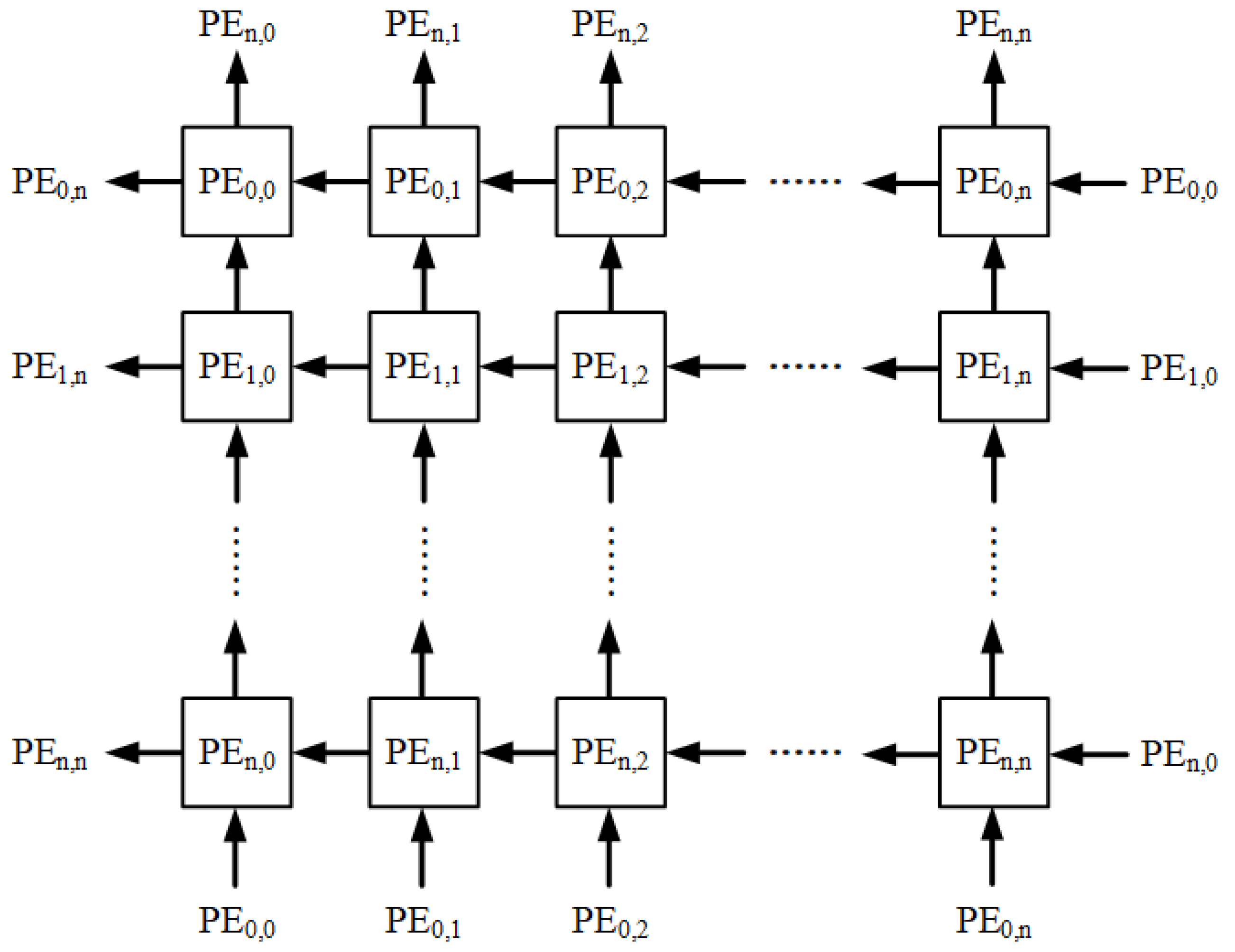
In conjunction with Cannon’s algorithm, each PE is connected to two registers, which store a value from the aligned matrix A and a value from the aligned matrix B, respectively. The PEs in the 0-th row are connected to those in the last row, and similarly, those in the 0-th column are connected to those in the last column, as illustrated in Figure 2.
Based on the initial alignment of matrix A and matrix B, corresponding values are simultaneously transmitted to each PE. Subsequently, multiply–accumulate operations are executed in all PEs. During each global matrix shifting, the values of matrix A are sent to the left neighboring PEs, while the values of matrix B are sent upward to the neighboring PEs. As a result, only n clock cycles are needed to complete the matrix multiplication.
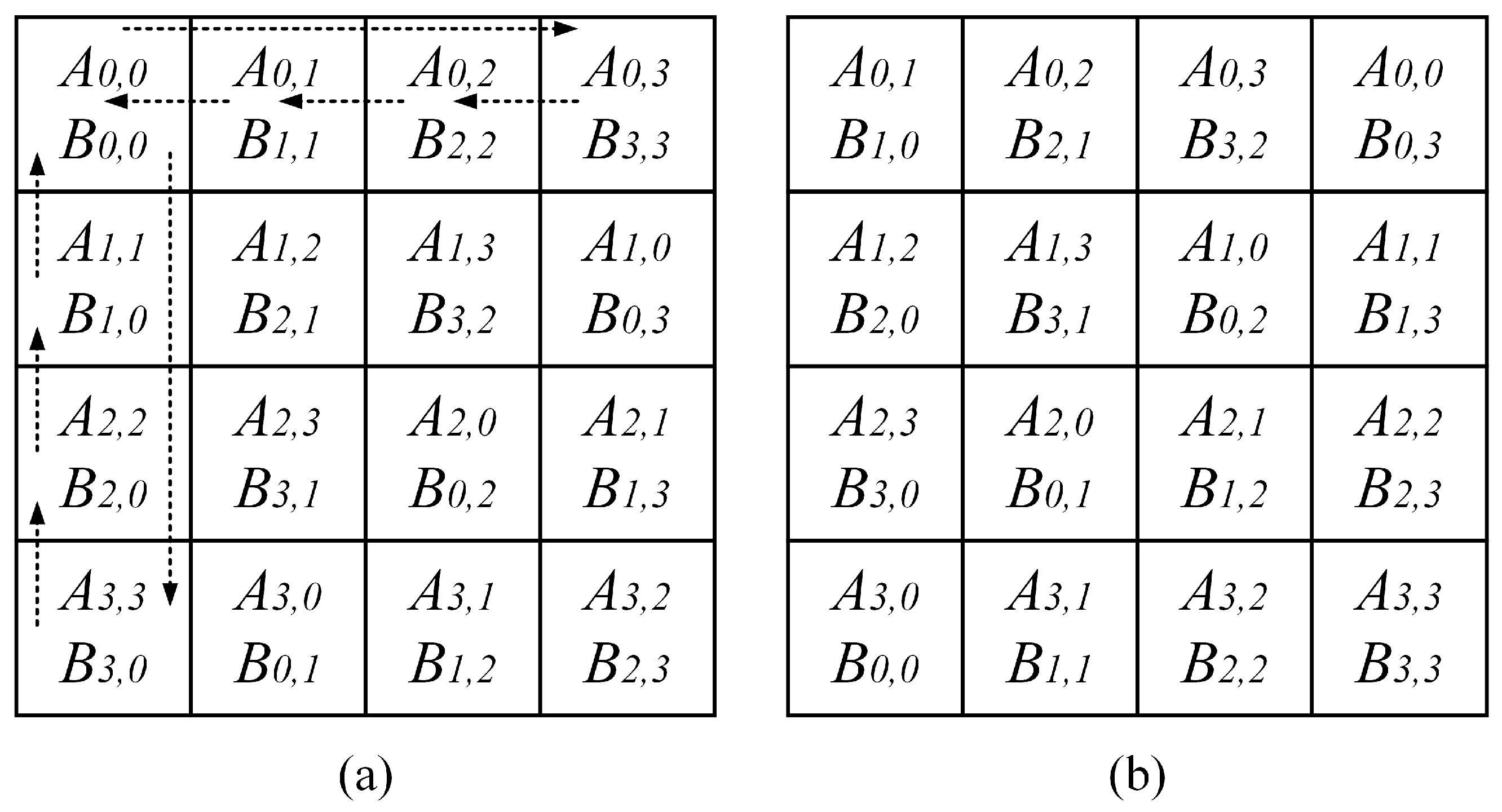
We illustrate an example using 4 × 4 matrix multiplication. Figure 3a overlaps the aligned matrix A and the aligned matrix B. For example, at this point, the elements overlapping at P E 1 , 2 are A 1 , 3 and B 3 , 2 . Next, we shift all elements of matrix A one step to the left and all elements of matrix B one step up. For clarity, in Figure 3a, we use the 0-th row as an example to indicate the shift direction of the elements in matrix A and the 0-th column as an example to indicate the shift direction of the elements in matrix B. Figure 3b gives the results after the first global matrix shifting is performed. As shown in Figure 3b, the elements overlapping at P E 1 , 2 become A 1 , 0 and B 0 , 2 . This process is repeated 4 times for multiply–accumulate and 3 times for global matrix shifting to obtain the final result. For instance, at the position P E 1 , 2 , we obtain the final result of C 1 , 2 as A 1 , 3 × B 3 , 2 + A 1 , 0 × B 0 , 2 + A 1 , 1 × B 1 , 2 + A 1 , 2 × B 2 , 2 .

2.3. Fault-Tolerant Matrix Multiplier Design

Jan and Huang [30] studied the fault-tolerant design of a systolic array executing Cannon’s algorithm for matrix multiplications. Their approach requires identifying fault-free columns, including those in the form of twisted columns.
Figure 4 is taken as an example. The PEs shaded in gray indicate faulty PEs. There are two twisted columns. One twisted column comprises P E 0 , 1 , P E 1 , 1 , P E 2 , 2 , and  P E 3 , 1 , while the other twisted column comprises P E 0 , 2 , P E 1 , 3 , P E 2 , 3 , and  P E 3 , 2 . From Figure 4, it can be observed that P E 0 , 1 performs the tasks that originally belonged to P E 0 , 0 and P E 0 , 1 , P E 1 , 1 performs the tasks that originally belonged to P E 1 , 0 and P E 1 , 1 , P E 2 , 2 performs the tasks that originally belonged to P E 2 , 0 and P E 2 , 1 , and so forth.
In [30], it is assumed that there exists a controller, referred to as a host control circuit, capable of directly transmitting data to each PE. This assumption is necessary because the systolic array must have data that correspond to aligned matrices to execute Cannon’s algorithm. Moreover, for each PE, the host control circuit needs to manage two multiplexers (in this PE) for data selection.
  • To circumvent faulty PEs when data flows from bottom to top, each PE can transmit data to the upper-left PE, the upper PE, and the upper-right PE, respectively. This means that in each PE, a multiplexer is required to select the data coming from the bottom-left PE, the bottom PE, the bottom-right PE, and the host control circuit.
  • To bypass a faulty PE when data flows from right to left, the data will pass through the faulty PE (without executing any multiply–accumulate operations) and enter the next PE in the subsequent cycle. This implies that in each PE, another multiplexer is necessary to choose the data arriving from the multiply–accumulate unit (MAC unit), the right PE, and the control circuit.
From the above discussion, we find that in the previous work, to support twisted columns, data may come from different directions, making the design of the host control circuit complex and adding extra circuits to each PE. Moreover, the previous work must find a fault-free column, which also limits the capability for fault tolerance.

3. The Proposed Approach

With analysis, we observe that in [30], there already exists a data transmission path between the host control circuit and each PE. Therefore, we propose a new fault-tolerant approach that utilizes the existing data transmission path between the host control circuit and each PE for data transfer, eliminating the need to search for a fault-free column. This approach not only simplifies the host control circuit but also streamlines the data path design of PEs.
It should be noted that our objective is to ensure the accuracy of matrix multiplication results. Therefore, the fault-tolerance issues that we address in matrix multiplication are different from those in the literature on DNN accelerators [31,32,33,34], which may tolerate some errors.
In this section, we introduce the proposed approach. Section 3.1 covers our fault-tolerance mechanism while also discussing the corresponding PE architecture. Section 3.2 presents two pair-matching algorithms: one-dimensional pair-matching and two-dimensional pair-matching.

3.1. Fault-Tolerance Mechanism and Corresponding PE Architecture

Note that, after post-manufacturing testing [14,15], the host control circuit can establish information about faulty PEs. Then, throughout the circuit’s lifespan, the number of faulty PEs may increase as the circuit ages. Hence, the host control circuit can incorporate run-time detection mechanisms [16,17] to dynamically update the information on faulty PEs.
The main drawback of the previous work [30] is the necessity to find at least one fault-free column (even in the form of a twisted column), which limits the potential for fault tolerance. Additionally, to support twisted columns, both the host control circuit and the data path of each PE incur significant additional circuitry, resulting in area overhead.
In contrast to the previous work, we adopt a pair-matching mechanism. For each faulty PE, we assign a fault-free PE to act as its proxy. In other words, this fault-free PE not only needs to complete its own task but also the task of its corresponding faulty PE. The proposed pair-matching mechanism does not require the identification of a fault-free column. Therefore, the proposed approach exhibits higher fault tolerance.
The proposed fault-tolerance mechanism follows the assumptions outlined in [30]. Firstly, we assume that faults in each PE can only occur in the MAC unit and not in the data transmission paths or storage components. Secondly, we assume the existence of data transmission paths between the host control circuit and each PE.
The proposed fault-tolerance mechanism consists of two stages:
  • In the first stage, Cannon’s algorithm is executed in the systolic array. Each fault-free PE completes the computations that it should perform. However, each faulty PE does not engage in computations. Nevertheless, during the process of global shifting, both faulty PEs and fault-free PEs engage in data transmissions.
  • In the second stage, the computations that each faulty PE should carry out are completed by the fault-free PE that it is acting as a proxy for. Since there are data transmission paths between the host control circuit and each PE, the data required by each fault-free PE can be directly transmitted by the host control circuit.
To implement the proposed fault-tolerance mechanism, we need to identify a fault-free PE to replace each faulty PE. The pairing of faulty PEs with fault-free PEs is managed by the host control circuit, which takes the matrix size and the list of faulty PEs as input. It then executes the pair-matching algorithm to establish the corresponding pairs. In Section 3.2, we will present two pair-matching algorithms. These two algorithms offer a trade-off between fault tolerance and controller area overhead.
In [30], the authors do not discuss the bandwidth of data transfer between the host control circuit and PEs. Therefore, here, we also assume no limitation on the data transfer bandwidth. It is worth noting that even if the data transfer bandwidth is limited, it does not affect the fault tolerance of our approach. However, if the data transfer bandwidth is limited, the time that it takes for the host control circuit to transmit data to PEs will be longer. For example, if the host control circuit can only transmit data to a maximum of 4 PEs at a time, it will need to transmit data to 8 PEs in two separate transmissions.
We illustrate our fault-tolerance mechanism with an example. In the first stage, the systolic array executes Cannon’s algorithm. Initially, based on the results of the initial alignment, the host control circuit sends data to each PE. Figure 5a depicts the overlap between the aligned matrix A and the aligned matrix B. For example, P E 0 , 0 receives data A 0 , 0 and B 0 , 0 , P E 0 , 1 receives data A 0 , 1 and B 1 , 1 , P E 0 , 2 receives data A 0 , 2 and B 2 , 2 , and so on. It is worth noting that PEs shaded in gray are faulty PEs. In other words, P E 0 , 1 , P E 0 , 3 , and  P E 3 , 3 are faulty PEs. Faulty PEs are unable to perform MAC operations but can still transmit data.
All fault-free PEs simultaneously perform MAC operations. Then, we conduct the first global matrix shifting. To clarify, in Figure 5a, we use the 0-th row as an example to demonstrate the shift direction of the elements in matrix A and the 0-th column as an example to demonstrate the shift direction of the elements in matrix B. The results of data transmission to each PE are shown in Figure 5b. Subsequently, all fault-free PEs simultaneously perform MAC operations again. Then, we conduct the second global matrix shifting, and the results of data transmission to each PE are shown in Figure 5c. Then, all fault-free PEs simultaneously perform MAC operations again. Following this, we proceed with the third global matrix shifting, and the results of data transmission to each PE are shown in Figure 5d. Finally, all fault-free PEs simultaneously perform MAC operations. At this point, each fault-free PE has completed its originally assigned task. For example, the accumulation result of P E 0 , 0 corresponds to the value of C 0 , 0 , where C 0 , 0 = A 0 , 0 × B 0 , 0 + A 0 , 1 × B 1 , 0 + A 0 , 2 × B 2 , 0 + A 0 , 3 × B 3 , 0 .
Next, we proceed to the second stage. Based on the outcomes of the pair-matching algorithm, the host control circuit assigns a fault-free PE to manage the tasks of each faulty PE. In Section 3.2, we will introduce two pair-matching algorithms. Here, we assume that the matching pairs are as follows: < P E 0 , 1 , P E 0 , 0 >, < P E 0 , 3 , P E 0 , 2 >, and < P E 3 , 3 , P E 3 , 0 >, where P E 0 , 0 takes over the task of P E 0 , 1 , P E 0 , 2 takes over the task of P E 0 , 3 , and P E 3 , 0 takes over the task of P E 3 , 3 .
In the second stage, only fault-free PEs serving as proxies perform MAC operations. Initially, the host control circuit sends data A 0 , 1 and B 1 , 1 to P E 0 , 0 , data A 0 , 3 and B 3 , 3 to P E 0 , 2 , and data A 3 , 2 and B 2 , 3 to P E 3 , 0 . The data transmission results are shown in Figure 6a. Subsequently, P E 0 , 0 , P E 0 , 2 , and  P E 3 , 0 simultaneously perform MAC operations. Then, the host control circuit sends data A 0 , 2 and B 2 , 1 to P E 0 , 0 , data A 0 , 0 and B 0 , 3 to P E 0 , 2 , and data A 3 , 3 and B 3 , 3 to P E 3 , 0 . The data transmission results are shown in Figure 6b. Afterwards, P E 0 , 0 , P E 0 , 2 , and  P E 3 , 0 simultaneously perform MAC operations. Next, the host control circuit sends data A 0 , 3 and B 3 , 1 to P E 0 , 0 , data A 0 , 1 and B 1 , 3 to P E 0 , 2 , and data A 3 , 0 and B 0 , 3 to P E 3 , 0 . The data transmission results are shown in Figure 6c. Then, P E 0 , 0 , P E 0 , 2 , and  P E 3 , 0 simultaneously perform MAC operations. Following that, the host control circuit sends data A 0 , 0 and B 0 , 1 to P E 0 , 0 , data A 0 , 2 and B 2 , 3 to P E 0 , 2 , and data A 3 , 1 and B 1 , 3 to P E 3 , 0 . The data transmission results are shown in Figure 6d. Subsequently, P E 0 , 0 , P E 0 , 2 , and  P E 3 , 0 simultaneously perform MAC operations. As a result, P E 0 , 0 , P E 0 , 2 , and  P E 3 , 0 complete their proxy tasks.
We illustrate with the pair < P E 0 , 1 , P E 0 , 0 >. P E 0 , 0 acts as the proxy for the tasks of P E 0 , 1 . Therefore, in this stage, P E 0 , 0 computes the value of C 0 , 1 , where C 0 , 1 = A 0 , 1 × B 1 , 1 + A 0 , 2 × B 2 , 1 + A 0 , 3 × B 3 , 1 + A 0 , 0 × B 0 , 1 .
Finally, let us discuss the architecture design of each PE. Our PE design is depicted in Figure 7. Essentially, each PE primarily executes MAC operations. For each PE, data for matrix A can be sourced either from the host control circuit (referred to as Controller-A in Figure 7) or from the PE located to the right (referred to as the east PE in Figure 7) because global matrix shifting necessitates shifting each element of matrix A to the left. Therefore, a two-to-one multiplexer is required to select the data source for matrix A. Similarly, for each PE, data for matrix B can be sourced either from the host control circuit (denoted as Controller-B in Figure 7) or from the PE located below (referred to as the south PE in Figure 7) because global matrix shifting requires shifting each element of matrix B upward. Thus, a two-to-one multiplexer is also necessary to select the data source for matrix B.
For each PE, due to global matrix shifting requiring each element of matrix A to shift left by one position, the data of matrix A need to be transmitted to the left-side PE (referred to as the west PE in Figure 7). Similarly, due to global matrix shifting necessitating each element of matrix B to shift upward by one position, the data of matrix B need to be transmitted to the PE above (referred to as the north PE in Figure 7). Upon completing all multiplications and accumulations, the final result is sent back to the host control circuit (referred to as Controller-R in Figure 7).
In comparison to the previous work [30], the data path of our PE is relatively simple, resulting in circuit area savings for the PE. Additionally, since our control logic is also relatively simple, the area of the controller (i.e., the host control circuit) can also be saved.

3.2. Proposed Pair-Matching Algorithms

In the proposed fault-tolerance mechanism, for each faulty PE, we must find a fault-free PE to act as its proxy in execution. Therefore, the host control circuit must employ a pair-matching algorithm. Considering hardware efficiency, we use the following two principles to develop the pair-matching algorithms:
  • Each fault-free PE can only proxy for at most one faulty PE. Thus, all tasks of faulty PEs can be executed simultaneously by fault-free PEs acting as their proxies.
  • We perform pair-matching independently for each row (or each column). Hence, pair-matching can be conducted in parallel for all rows (or all columns).
We refer to the scheme of performing pair-matching independently for each row as row-based pair-matching. Similarly, the scheme of performing pair-matching independently for each column is referred to as column-based pair-matching. Essentially, the concepts of row-based pair-matching and column-based pair-matching are identical. Without loss of generality, we illustrate the row-based pair-matching scheme using Figure 8.
For each row, the number of matching pairs is the minimum of the number of faulty PEs and the number of fault-free PEs in that row. In Figure 8, we illustrate this using row 0. Since there are 3 faulty PEs (i.e., P E 0 , 0 , P E 0 , 2 , and  P E 0 , 5 ) and 4 fault-free PEs (i.e., P E 0 , 1 , P E 0 , 3 , P E 0 , 4 , and  P E 0 , 5 ) in this row, the number of matching pairs is 3 (i.e., min(3,4) = 3). We scan from left to right in our row-based matching approach. The first faulty PE is P E 0 , 0 , and the first fault-free PE is P E 0 , 1 , so the first matching pair is < P E 0 , 0 , P E 0 , 1 >. The second faulty PE is P E 0 , 2 , and the second fault-free PE is P E 0 , 3 , so the second matching pair is < P E 0 , 2 , P E 0 , 3 >. The third faulty PE is P E 0 , 5 , and the third fault-free PE is P E 0 , 4 , so the third matching pair is < P E 0 , 5 , P E 0 , 4 >.
Based on the row-based pair-matching scheme and the column-based pair-matching scheme, we present two pair-matching algorithms.
  • One-dimensional pair-matching algorithm: This algorithm only executes the row-based pair-matching scheme.
  • Two-dimensional pair-matching algorithm: This algorithm first executes the row-based pair-matching scheme. If there are faulty PEs that fail to complete pairing, this algorithm then attempts pairing using the column-based pair-matching scheme.
Clearly, the control logic of the one-dimensional pair-matching algorithm is simpler, but its fault tolerance is lower. Conversely, the control logic of the two-dimensional pair-matching algorithm is more complex, but its fault tolerance is higher.
Algorithm  1 displays the proposed one-dimensional pair-matching algorithm. For each row, the number of matching pairs corresponds to the minimum value between the number of faulty PEs and the number of fault-free PEs in that row. We define r p [ i ] as the number of matching pairs in row i. Each matching pair is assigned a unique index (starting from 0). We define i n d e x [ i ] as the index of the first matching pair in row i. In other words, we have i n d e x [ 0 ] = 0 . For index i, where i > 0 , we have Equation (4) as follows:
i n d e x [ i ] = s = 0 i 1 r p [ s ]
Algorithm 1 One-Dimensional Pair-Matching
  1:
for i from 0 to n 1  do
  2:
      for j from 0 to n 1  do
  3:
           k = i n d e x [ i ] ;
  4:
           p = 0; q =0;
  5:
           if  P E i , j is faulty then
  6:
                 if p < r p [ i ]  then
  7:
                       assign P E i , j as the faulty PE of p a i r [ k + p ] ;
  8:
                       p = p+1;
  9:
                 end if
10:
           else
11:
                if q < r p [ i ]  then
12:
                       assign P E i , j as the fault-free PE of p a i r [ k + q ] ;
13:
                       q = q+1;
14:
                end if
15:
           end if
16:
      end for
17:
end for
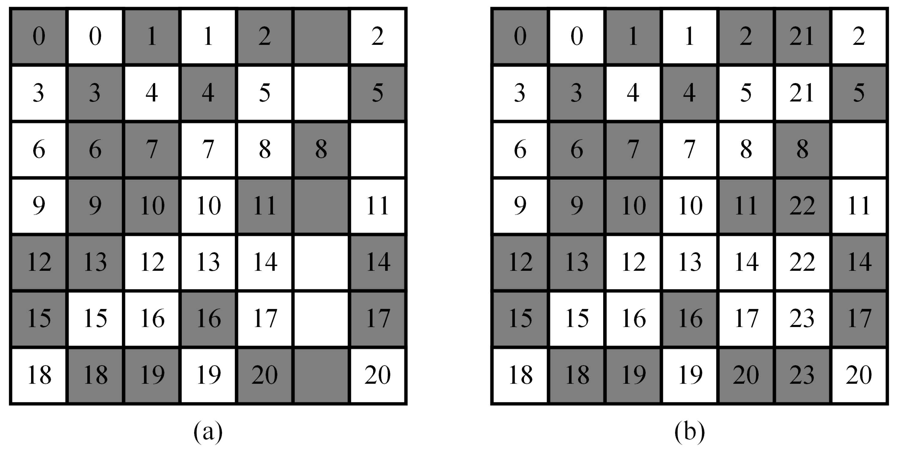
We use the PE array shown in Figure 9a for illustration. In Figure 9a, row 0 has 3 faulty PEs and 4 fault-free PEs. Thus, we have r p [ 0 ] = 3 . Since we start indexing from 0, we have i n d e x [ 0 ] = 0 . Row 1 has 3 faulty PEs and 4 fault-free PEs. Thus, we have r p [ 1 ] = 3 . The index of the first matching pair in row 1 is 3, so i n d e x [ 1 ] = 3 . Row 2 also has 3 faulty PEs and 4 fault-free PEs. Thus, r p [ 2 ] = 3 . The index of the first matching pair in row 2 is 6, so i n d e x [ 2 ] = 6 .
The controller (i.e., the host control circuit) can easily determine the value of i n d e x [ i ] for each row i. Since each row knows the index of its first matching pair, in hardware implementation, each row can proceed in parallel using the row-based pair-matching scheme. In Algorithm 1, we employ an array named “pair” to store matching pairs. Each matching pair within this array comprises a faulty PE and a fault-free PE, organized based on their respective indices.
We illustrate the proposed one-dimensional pair-matching algorithm (i.e., Algorithm 1) using the PE array in Figure 9a. From Figure 9a, we have i n d e x [ 0 ] = 0 , i n d e x [ 1 ] = 3 , i n d e x [ 2 ] = 6 , i n d e x [ 3 ] = 9 , i n d e x [ 4 ] = 12 , i n d e x [ 5 ] = 15 , and i n d e x [ 6 ] = 18 . Then, we can perform the row-based pair-matching scheme for each row. As a result, we can obtain the results, as displayed in Figure 9b.
Next, we extend the proposed one-dimensional pair-matching algorithm to a two-dimensional context. Our two-dimensional pair-matching algorithm includes two phases: in the first phase, we apply the row-based pair-matching scheme for each row. The task of this phase is the same as that of our one-dimensional pair-matching algorithm. However, we must mark the PEs that have been paired. In the second phase, we apply the column-based pair-matching scheme for each column. In this phase, we only need to perform pair-matching for unmarked PEs (i.e., PEs that have not yet been paired).
In the second phase, since we only consider unmarked PEs, for each column, the number of matching pairs is the minimum value of the number of unmarked faulty PEs and the number of unmarked fault-free PEs in this column. We define c p [ j ] as the number of matching pairs in column j. We also continue to assign a unique index to each matching pair (continuing from the numbering in the first phase). We define c o l _ i n d e x [ j ] as the index of the first matching pair in column j. In other words, we have Equation (5) as follows:
c o l _ i n d e x [ 0 ] = s = 0 n r p [ s ]
For j > 0 , we have Equation (6) as follows:
c o l _ i n d e x [ j ] = s = 0 n r p [ s ] + s = 0 j 1 c p [ s ]
We illustrate the proposed two-dimensional pair-matching algorithm using Figure 10 as an example. In the first phase, we apply the row-based pair-matching scheme. The results of the first phase are displayed in Figure 10a. Upon completion of the first phase, we have 21 matching pairs (numbered from 0 to 20). However, we find that in column 5, there are still 3 faulty PEs that have not been paired.
In the second phase of the proposed two-dimensional pair-matching algorithm, we only consider unmarked PEs. Thus, we have c p [ 0 ] = 0 , c p [ 1 ] = 0 , c p [ 2 ] = 0 , c p [ 3 ] = 0 , c p [ 4 ] = 0 , c p [ 5 ] = 3 , and c p [ 6 ] = 0 . Therefore, since we continue numbering from the first phase, we have c o l _ i n d e x [ 0 ] = 21 , c o l _ i n d e x [ 1 ] = 21 , c o l _ i n d e x [ 2 ] = 21 , c o l _ i n d e x [ 3 ] = 21 , c o l _ i n d e x [ 4 ] = 21 , c o l _ i n d e x [ 5 ] = 21 , and c o l _ i n d e x [ 6 ] = 24 .
Then, we apply the column-based pair-matching scheme for each column. After applying the column-based pair-matching scheme, the three faulty PEs in column 5 can be paired (the indices of these matching pairs are 21, 22, and 23). Upon completion of the second phase, we obtain the results, as displayed in Figure 10b. We find that all of the faulty PEs have been paired.
It is noteworthy that the proposed pair-matching algorithms, including both our one-dimensional and two-dimensional approaches, can be implemented in either software or hardware. However, for real-time applications, it is essential to implement these algorithms in hardware circuits to achieve high speed.

4. Experimental Results

In the experiments, we address the fault-tolerance capability and circuit area overhead of the proposed approach. For comparison, we also implemented the approach presented by Jan and Huang [30].
Regarding the fault-tolerance capability, we conducted separate analyses on an 8 × 8 systolic array, 16 × 16 systolic array, and 32 × 32 systolic array. We randomly assume the positions of faulty PEs within the systolic arrays. Then, we can evaluate the fault-tolerance capabilities of different methods (including the proposed one-dimensional pair-matching algorithm, the proposed two-dimensional pair-matching algorithm, and the approach proposed by Jan and Huang [30]).
The detailed analysis methodology is as follows. Given a specific number of faulty PEs, we randomly generate the locations of these faulty PEs. Additionally, for each specific number of faulty PEs, we generate 10,000 cases randomly. For each case, we analyze whether various methods (including the proposed one-dimensional pair-matching algorithm, the proposed two-dimensional pair-matching algorithm, and the approach proposed by Jan and Huang [30]) can successfully tolerate faults. Subsequently, we can calculate the probability of success (i.e., the success rate) of each method concerning a specific number of faulty PEs.
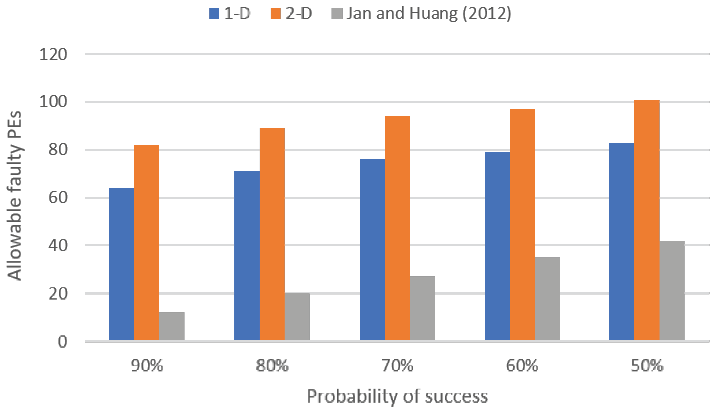
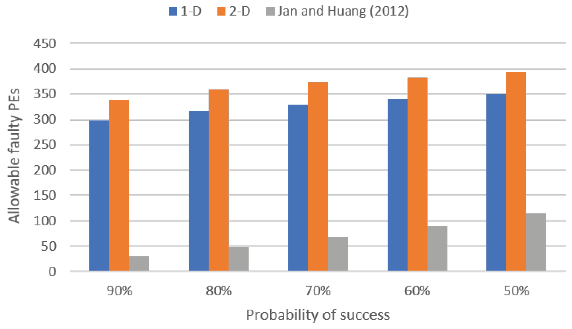
Figure 11, Figure 12, and Figure 13 depict our analysis results for the 8 × 8 systolic array, 16 × 16 systolic array, and 32 × 32 systolic array, respectively. In these figures, 1-D represents the proposed one-dimensional pair-matching algorithm, 2-D represents the proposed two-dimensional pair-matching algorithm, and Jan an Huang (2012) represents the method presented in [30]. Moreover, in these figures, the x-axis represents the probability of success (i.e., the success rate), and the y-axis represents the allowable quantity of faulty PEs. For instance, as shown in Figure 11, to attain a success rate of 90% in an 8 × 8 systolic array, the permissible numbers of faulty PEs for our one-dimensional pair-matching algorithm, our two-dimensional pair-matching algorithm, and the method proposed in [30] are 14, 21, and 4, respectively; as shown in Figure 11, to attain a success rate of 80% in an 8 × 8 systolic array, the permissible numbers of faulty PEs for our one-dimensional pair-matching algorithm, our two-dimensional pair-matching algorithm, and the method proposed in [30] are 16, 23, and 6, respectively.
From Figure 11, Figure 12 and Figure 13, we observe that our two-dimensional pair-matching algorithm exhibits the highest fault-tolerance capability. Furthermore, we also note that both the proposed one-dimensional pair-matching algorithm and the proposed two-dimensional pair-matching algorithm outperform the approach presented in [30] in terms of fault tolerance. Essentially, the approach presented in [30] is only suitable for scenarios with a smaller number of faulty PEs. In contrast, both our one-dimensional pair-matching algorithm and our two-dimensional pair-matching algorithm can be applied in situations with a higher number of faulty PEs.
Next, we explore the circuit area overhead. For our implementations, we assume that the size of the systolic array is 8 × 8 . The circuits are implemented using the TSMC 40 nm cell library. We begin by analyzing the area of the controller (i.e., the host control circuit). Table 1 presents the controller area for executing the proposed one-dimensional pair-matching algorithm (referred to as 1-D), the proposed two-dimensional pair-matching algorithm (referred to as 2-D), and the method proposed in [30]. As depicted in Table 1, the controller area utilizing the proposed one-dimensional pair-matching algorithm is the smallest. Conversely, the controller area of the approach proposed in [30] is the largest. This is because their twisted column scheme is more complex than the proposed pair-matching scheme.
We also examine the areas occupied by PEs. Table 2 presents the areas of various PE designs, including the conventional PE design (i.e., without any fault-tolerance mechanism), our PE design, and the approach proposed in [30]. In comparison to the conventional PE design, our area overhead is only 6%. It is noteworthy to mention that the conventional PE design lacks a fault-tolerance mechanism. On the other hand, when compared with the conventional PE design, the area overhead of the approach proposed in [30] reaches 70% (owing to the twisted column scheme). Therefore, the area overhead of our PE design is small.
Note that Table 2 refers to the area of a single PE. When considering a PE array, its total area can be determined by multiplying the area of a single PE by the array size. Therefore, for PE arrays of the same size, compared to utilizing the conventional PE design, the area overhead of employing our PE design remains at 6%, while the area overhead of utilizing the approach proposed in [30] also stands at 70%.

5. Conclusions

This paper introduces a highly fault-tolerant approach designed for a systolic array executing Cannon’s algorithm for matrix multiplication. Our core concept involves pairing each faulty PE with a corresponding fault-free PE to serve as its proxy. We propose two pair-matching algorithms: one-dimensional pair-matching and two-dimensional pair-matching. These two pair-matching algorithms offer a trade-off between fault tolerance capability and circuit area overhead. We employed the TSMC 40 nm process technology to implement the proposed approach. The experimental results demonstrate that, compared to the previous work, our approach (whether employing our one-dimensional pair-matching algorithm or our two-dimensional pair-matching algorithm) not only improves fault tolerance but also reduces circuit area overhead. In certain application domains, such as space or deep-sea exploration, repairs are challenging even if many PEs fail. Therefore, the proposed approach is particularly well-suited for these applications.
Since our current pair-matching algorithms necessitate finding a dedicated fault-free PE to substitute for each faulty PE, the number of faulty PEs cannot exceed half of the total PE count. Our future work will concentrate on developing methods to overcome this limitation.

Author Contributions

Conceptualization, investigation, and methodology, H.-C.L., L.-Y.S. and S.-H.H.; validation and formal analysis, H.-C.L. and L.-Y.S.; writing—original draft preparation, H.-C.L.; writing—review and editing, L.-Y.S. and S.-H.H.; supervision, S.-H.H. All authors have read and agreed to the published version of the manuscript.

Funding

This work was supported in part by the National Science and Technology Council, Taiwan, under grant number 112-2221-E-033-050-MY3.

Data Availability Statement

The data used to support the findings of this study are included in this paper.

Conflicts of Interest

The authors declare no conflicts of interest.

References

  1. Cannon, L. A Cellular Computer to Implement The Kalman Filter Algorithm. Ph.D. Dissertation, Montana State University, Bozeman, MT, USA, 1969. [Google Scholar]
  2. Coppersmith, D.; Winograd, S. Matrix Multiplication via Arithmetic Progressions. In Proceedings of the Annual ACM Symposium on Theory of Computing, New York, NY, USA, 25–27 May 1987; pp. 1–6. [Google Scholar]
  3. Kung, H. Why Systolic Architectures? Computer 1982, 15, 37–46. [Google Scholar] [CrossRef]
  4. Wei, X.; Yu, C.; Zhang, P.; Chen, Y.; Wang, Y.; Hu, H.; Liang, Y.; Cong, J. Automated Systolic Array Architecture Synthesis for High Throughput CNN Inference on FPGAs. In Proceedings of the ACM/IEEE Design Automation Conference, Austin, TX, USA, 18–22 June 2017; pp. 1–6. [Google Scholar]
  5. Lahari, P.; Yellampalli, S.; Vaddi, R. Systolic Array Based Multiply Accumulation Unit for IoT Edge Accelerators. In Proceedings of the IEEE International Symposium on Smart Electronic Systems, Jaipur, India, 18–22 December 2021; pp. 220–223. [Google Scholar]
  6. Chiper, D.; Cracan, A.; Andries, V.D. An Overview of Systolic Arrays for Forward and Inverse Discrete Sine Transforms and Their Exploitation in View of an Improved Approach. Electronics 2022, 11, 2416. [Google Scholar] [CrossRef]
  7. Inayat, K.; Muslim, F.B.; Iqbal, J.; Hassnain Mohsan, S.; Alkahtani, H.; Mostafa, S. Power-Intent Systolic Array Using Modified Parallel Multiplier for Machine Learning Acceleration. Sensors 2023, 23, 4297. [Google Scholar] [CrossRef] [PubMed]
  8. Aviles, P.; Schäfer, L.; Lindoso, A.; Belloch, J.; Entrena, L. High Complexity Reliable Space Applications in Commercial Microprocessors. Microelectron. Reliab. 2022, 138, 114679. [Google Scholar] [CrossRef]
  9. Ra, H.; Youn, C.; Kim, K. High-Reliability Underwater Acoustic Communication Using an M-ary Cyclic Spread Spectrum. Electronics 2022, 11, 1698. [Google Scholar] [CrossRef]
  10. O’Dougherty, P.; Ferrel, K.; Varol, S. A Study of Semiconductor Defects within Automotive Manufacturing using Predictive Analytics. In Proceedings of the IEEE International Symposium on Digital Forensics and Security, Elazig, Turkey, 28–29 June 2021; pp. 1–6. [Google Scholar]
  11. Kundu, S.; Banerjee, S.; Raha, A.; Natarajan, S.; Basu, K. Toward Functional Safety of Systolic Array-Based Deep Learning Hardware Accelerators. IEEE Trans. Very Large Scale Integr. (VLSI) Syst. 2021, 29, 485–498. [Google Scholar] [CrossRef]
  12. Huang, S.H.; Tu, W.P.; Chang, C.M.; Pan, S.B. Low-power Anti-aging Zero Skew Clock Gating. ACM Trans. Des. Autom. Electron. Syst. 2013, 18, 27. [Google Scholar] [CrossRef]
  13. Meric, I.; Ramey, S.; Novak, S.; Gupta, S.; Mudanai, S.P.; Hicks, J. Modeling Framework for Transistor Aging Playback in Advanced Technology Nodes. In Proceedings of the IEEE International Reliability Physics Symposium, Dallas, TX, USA, 28 April–30 May 2020; pp. 1–6. [Google Scholar]
  14. Cheong, M.; Lee, I.; Kang, S. A Test Methodology for Neural Computing Unit. In Proceedings of the IEEE International SoC Design Conference, Daegu, Republic of Korea, 12–15 November 2018; pp. 11–12. [Google Scholar]
  15. Solangi, U.; Ibtesam, M.; Ansari, M.; Kim, J.; Park, S. Test Architecture for Systolic Array of Edge-Based AI Accelerator. IEEE Access 2021, 9, 96700–96710. [Google Scholar] [CrossRef]
  16. Vijayan, A.; Koneru, A.; Kiamehr, S.; Chakrabarty, K.; Tahoori, M. Fine-Grained Aging-Induced Delay Prediction Based on the Monitoring of Run-Time Stress. IEEE Trans. Comput.-Aided Des. Integr. Circuits Syst. 2018, 37, 1064–1075. [Google Scholar] [CrossRef]
  17. Huang, K.; Hasan, A.M.T.; Zhang, X.; Karimi, N. Real-Time IC Aging Prediction via On-Chip Sensors. In Proceedings of the IEEE Computer Society Annual Symposium on VLSI, Tampa, FL, USA, 7–9 July 2021; pp. 13–18. [Google Scholar]
  18. Bjelica, M.; Mrazovac, B. Reliability of Self-Driving Cars: When Can We Remove the Safety Driver? IEEE Intell. Transp. Syst. Mag. 2023, 15, 46–54. [Google Scholar] [CrossRef]
  19. Wahba, A.; Fahmy, H. Area Efficient and Fast Combined Binary/Decimal Floating Point Fused Multiply Add Unit. IEEE Trans. Comput. 2017, 66, 226–239. [Google Scholar] [CrossRef]
  20. Tung, C.W.; Huang, S.H. A High-Performance Multiply-Accumulate Unit by Integrating Additions and Accumulations into Partial Product Reduction Process. IEEE Access 2020, 8, 87367–87377. [Google Scholar] [CrossRef]
  21. She, X.; Li, N.; Jensen, D. SEU Tolerant Memory Using Error Correction Code. IEEE Trans. Nucl. Sci. 2012, 59, 205–210. [Google Scholar] [CrossRef]
  22. Wu, M.S.; Chua, Y.L.; Li, J.F.; Chuan, Y.T.; Huang, S.H. Fault-Aware ECC Scheme for Enhancing the Read Reliability of STT-MRAMs. In Proceedings of the IEEE International Test Conference in Asia, Matsue, Japan, 13–15 September 2023; pp. 1–6. [Google Scholar]
  23. Chen, T.J.; Li, J.F.; Tseng, T.W. Cost-efficient Built-in Redundancy Analysis with Optimal Repair Rate for RAMs. IEEE Trans. Comput.-Aided Des. Integr. Circuits Syst. 2012, 31, 930–940. [Google Scholar] [CrossRef]
  24. Lee, H.; Kim, J.; Cho, K.; Kang, S. Fast Built-in Redundancy Analysis Based on Sequential Spare Line Allocation. IEEE Trans. Reliab. 2018, 67, 264–273. [Google Scholar] [CrossRef]
  25. Johnson, J.; Wirthlin, M. Voter Insertion Algorithms for FPGA Designs Using Triple Modular Redundancy. In Proceedings of the ACM International Symposium on Field Programmable Gate Arrays, Monterey, CA, USA, 21–23 February 2010; pp. 249–258. [Google Scholar]
  26. Santhiya, M.; Saranya, S.; Vijayachitra, S.; Lavanya, C.; Rajarajeswari, M. Application of Voter Insertion Algorithm for Fault Management Using Triple Modular Redundancy (TMR) Technique. In Proceedings of the IEEE International Conference on Intelligent Communication Technologies and Virtual Mobile Networks, Tirunelveli, India, 4–6 February 2021; pp. 578–583. [Google Scholar]
  27. Kim, J.; Reddy, S. On The Design of Fault-Tolerant Two-Dimensional Systolic Arrays for Yield Enhancement. IEEE Trans. Comput. 1989, 38, 515–525. [Google Scholar] [CrossRef]
  28. Stojanovic, N.; Milovanovic, E.; Stojmenovic, I.; Milovanovic, T.; Tokic, T. Mapping Matrix Multiplication Algorithm onto Fault-Tolerant Systolic Array. Comput. Math. Appl. 2004, 48, 275–289. [Google Scholar] [CrossRef]
  29. Milovanovic, I.; Milovanovic, E.; Stojcev, M. A Class of fault-Tolerant Systolic Arrays for Matrix Multiplication. Math. Comput. Model. 2011, 54, 140–151. [Google Scholar] [CrossRef]
  30. Jan, B.Y.; Huang, J.L. A Fault-Tolerant PE Array Based Matrix Multiplier Design. In Proceedings of the IEEE VLSI Design, Automation and Test, Hsinchu, Taiwan, 23–25 April 2012; pp. 1–4. [Google Scholar]
  31. Zhang, J.; Gu, T.; Basu, K.; Garg, S. Analyzing and Mitigating The Impact of Permanent Faults on a Systolic Array Based Neural Network Accelerator. In Proceedings of the IEEE VLSI Test Symposium, San Francisco, CA, USA, 22–25 April 2018; pp. 1–6. [Google Scholar]
  32. Zhang, J.; Basu, K.; Garg, S. Fault-Tolerant Systolic Array Based Accelerators for Deep Neural Network Execution. IEEE Des. Test 2019, 36, 44–53. [Google Scholar] [CrossRef]
  33. Zhao, Y.; Wang, K.; Louri, A. FSA: An Efficient Fault-tolerant Systolic Array-based DNN Accelerator Architecture. In Proceedings of the IEEE International Conference on Computer Design, Olympic Valley, CA, USA, 23–26 October 2022; pp. 545–552. [Google Scholar]
  34. Moghaddasi, I.; Gorgin, S.; Lee, J.A. Dependable DNN Accelerator for Safety-Critical Systems: A Review on the Aging Perspective. IEEE Access 2023, 11, 89803–89834. [Google Scholar] [CrossRef]
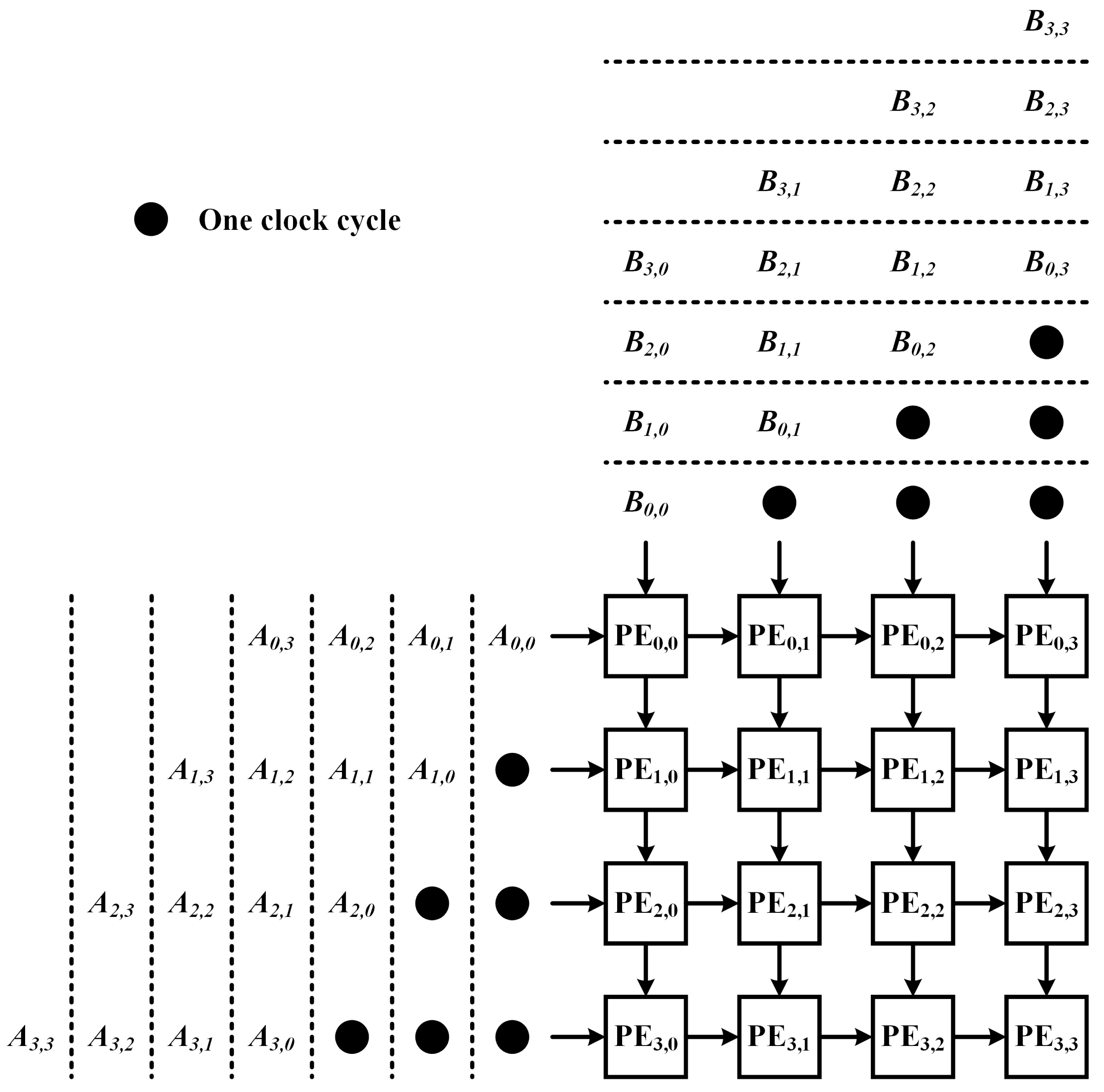
Figure 1. A 4 × 4 systolic array for matrix multiplications.
Electronics 13 01780 g001
Figure 2. The systolic array architecture applied to Cannon’s algorithm.
Electronics 13 01780 g002
Figure 3. (a) The overlap of aligned matrices A and B. (b) The results after the first global matrix shifting.
Electronics 13 01780 g003
Figure 4. An example of twisted columns.
Electronics 13 01780 g004
Figure 5. The first stage of our fault-tolerance mechanism.
Electronics 13 01780 g005
Figure 6. The second stage of our fault-tolerance mechanism.
Electronics 13 01780 g006
Figure 7. The architecture of our PE.
Electronics 13 01780 g007
Figure 8. Illustration of the row-based pair-matching scheme.
Electronics 13 01780 g008
Figure 9. An example of our one-dimensional pair-matching algorithm.
Electronics 13 01780 g009
Figure 10. An example of our two-dimensional pair-matching algorithm.
Electronics 13 01780 g010
Figure 11. The fault-tolerance capabilities of different methods in an 8 × 8 systolic array. The bar Jan and Huang (2012) denotes the method proposed in [30].
Electronics 13 01780 g011
Figure 12. The fault-tolerance capabilities of different methods in a 16 × 16 systolic array. The bar Jan and Huang (2012) denotes the method proposed in [30].
Electronics 13 01780 g012
Figure 13. The fault-tolerance capabilities of different methods in a 32 × 32 systolic array. The bar Jan and Huang (2012) denotes the method proposed in [30].
Electronics 13 01780 g013
Table 1. Comparison of the areas of controllers.
AlgorithmArea
1-D9553 μ m 2
2-D11,675 μ m 2
 [30]14,589 μ m 2
Table 2. Comparison of the areas of different PE designs.
PE DesignAreaNormalization
Conventional434 μ m 2 100%
Ours462 μ m 2 106%
 [30]736 μ m 2 170%
Disclaimer/Publisher’s Note: The statements, opinions and data contained in all publications are solely those of the individual author(s) and contributor(s) and not of MDPI and/or the editor(s). MDPI and/or the editor(s) disclaim responsibility for any injury to people or property resulting from any ideas, methods, instructions or products referred to in the content.