Abstract
The Dual Carry Approximate Adder (DCAA) is proposed as an advanced 8-bit approximate adder featuring dual carry-out and carry-in full adders (FAs) along with an Error Reduction Unit (ERU) to enhance accuracy. The 8-bit adder is partitioned into upper and lower 4-bit blocks, connected via a dual carry-out full adder and a dual carry-in full adder. To minimize impact on the critical path, an ERU is designed for efficient error correction. Four variants of the DCAA are provided, allowing users to select the most suitable design based on their specific power, area, and accuracy requirements. The DCAA achieves a 78% reduction in Mean Error Distance (MED) while maintaining high computational speed and efficiency. When applied to Wallace Tree multipliers, it reduces delay by 32% compared to ripple carry adders (RCAs), and in in-memory computing (IMC) architectures, it significantly improves accuracy with minimal delay overhead. Experimental results demonstrate that the DCAA offers a well-balanced trade-off between accuracy, speed, and resource efficiency, making it suitable for high-performance, error-tolerant applications. Compared to existing approximate adders, DCAA exhibits superior error correction capabilities while achieving significantly lower delay. Furthermore, its efficient hardware implementation enables seamless integration into various computing paradigms, including AI accelerators and neuromorphic processors. Additionally, the scalability of the design allows for flexible adaptation to different bit-widths, making it a versatile solution for next-generation computing architectures.
1. Introduction
The increasing demand for high-speed and energy-efficient computing systems has driven significant advancements in computational paradigms. Approximate computing offers a promising solution for achieving high-speed performance, particularly in error-tolerant applications. However, one of the critical challenges in approximate computing lies in the inherent inaccuracies introduced by approximate adders, making effective error reduction a crucial aspect for reliable computation.
Meanwhile, in-memory computing (IMC) presents a transformative approach to overcoming the von Neumann bottleneck by performing computations directly within the memory. This integration minimizes data movement overhead, significantly improving both system performance and energy efficiency. By integrating approximate computing with IMC, computational speed can be further enhanced through a synergistic approach. By combining the error-tolerant nature of approximate computing with the reduced data movement of IMC, this paradigm achieves not only faster processing but also improved energy efficiency. This integration enables high-speed operations directly within the memory, bypassing the traditional delays associated with data transfer between processing units and memory.
In arithmetic circuits, approximate adders play a crucial role by trading off computational accuracy for improved speed, reduced power consumption, and area efficiency. However, conventional approximate adders suffer from significant error metrics, such as high Mean Error Distance (MED), Mean Relative Error Distance (MRED), and error rate (ER), which can limit their applicability in accuracy-sensitive domains.
In recent years, research on approximate adders has expanded significantly, especially in the context of energy-efficient computing. Recent studies, such as [1,2], have proposed novel approaches for improving the performance of approximate adders while maintaining a balance between accuracy and power efficiency. The work by Vendhan et al. (2025) [1] introduces dynamic reconfiguration methods for approximate adders, allowing tunable accuracy based on application needs, which aligns with the approach proposed in this paper. Furthermore, Wu et al. (2025) [2] provides a comprehensive survey of multiplier designs, offering insight into the importance of energy-efficient designs for high-performance computing, which has influenced the development of our DCAA design.
To address this limitation, the Dual Carry Approximate Adder (DCAA), equipped with an Error Reduction Unit (ERU), was developed to significantly enhance accuracy compared to conventional approximate adders. The improved accuracy of the DCAA has been demonstrated in multiple applications, including Wallace Tree multipliers and IMC architecture. In the Wallace Tree multiplier, widely regarded for its efficiency in multiplication operations, the DCAA was integrated into the partial sum computation stages, resulting in notable improvements in both delay and accuracy. Similarly, in IMC architecture, where SRAM-based logic is employed the DCAA with its ERU significantly enhanced accuracy while incurring only a slight increase in delay compared to IMC systems using conventional approximate adders.
2. Proposed Methodology and Applications
2.1. Dual Carry Approximate Adder (DCAA) and Error Reduction Unit (ERU)
2.1.1. Dual Carry Approximate Adder (DCAA)
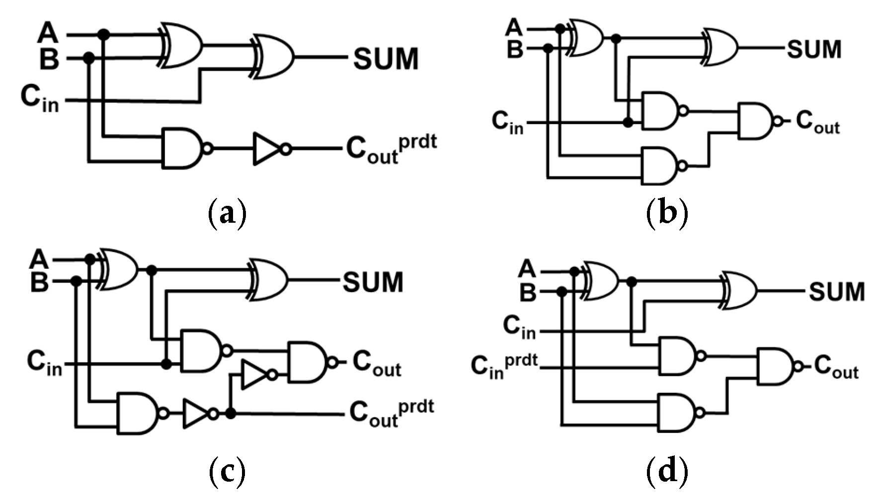
The dual carry-out and dual carry-in full adders (FAs) are similar to the 1-bit FA but they exhibit significant differences in terms of inputs and outputs as shown in Figure 1. The dual carry-out FA produces outputs both a precise and predicted carry, similar to carry-out selectable FA of SARA [3]. It includes two additional inverters compared to the 1-bit FA. Equations (1)–(3) present the three outputs of the dual carry-out FA.
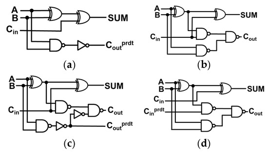
Figure 1.
(a) AFA3 [4], (b) conventional FA, (c) dual carry-out FA, and (d) dual carry-in FA.
The dual carry-in full adder (FA) accepts both a precise and predicted carry, computed by the dual carry-out FA. Similar to carry-in configurable FA of SARA [3], it uses the carry-in predict () for computation. Equations (1) and (4) detail these computations.
2.1.2. Error Reduction Unit (ERU)
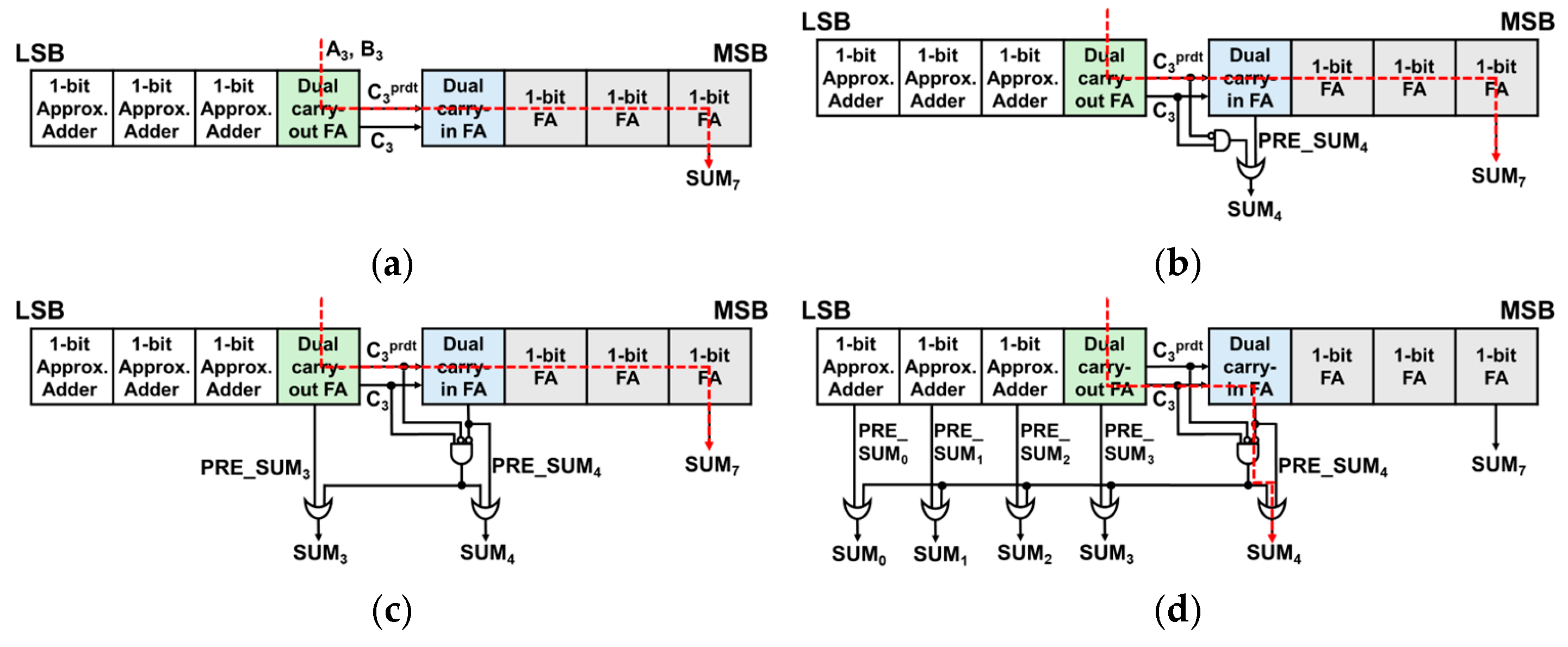
The 8-bit DCFA w/o ERU, displayed in Figure 2a, employs a 1-bit FA for the top 4 bits and an AFA3 [4] for the bottom 3 bits. The AFA3, similar to other approximate adders discussed in [5,6], can lead to errors in some cases.
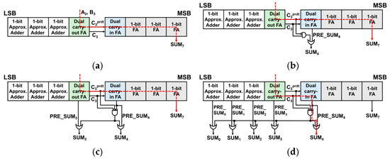
Figure 2.
8-bit DCFA-based approximate adders (with red dashed line indicating critical paths), (a) w/o ERU, (b) w/ERU_simple, (c) w/ERU_plus, and (d) w/ERU_max.
The 8-bit DCFA w/o ERU approach, which is depicted on Figure 2a, eliminates the MUX entirely, unlike SARA [3], enabling the carry chain to speed up by bypassing MUX. Only is used exclusively for calculating the carry chain, while the exact C3 value is utilized for computing the sum. Although there is a notable improvement in the delay, the accuracy did not meet the anticipated improvement. This necessitates further exploration into strategies for minimizing the error distance.
Adding the ERU aims to balance delay reduction and error minimization. In 4:4 approximate adders, the fourth bit position (SUM₄) often produces large error distances when the predicted and actual carry () differ. This discrepancy can result in high-weight bit errors (e.g., 32 or 36). The proposed ERU selectively activates correction only when this condition is detected, using Equation (5), and avoids overcompensation via the condition , which ensures that only significant errors are targeted.
As shown in Figure 2b, ERU_simple by adding ERU to only SUM4, removes error distances like 36 or 32. ERUs are also attached to both SUM4 and lower 4 bits to reduce errors on still large values. However, multi-bit ERUs require circuit modifications for precise corrections without overcompensation. Additionally, a condition is introduced to prevent excessive corrections by satisfying PRE_SUM0 = 0. Equation (5) is the formula for the ERU circuit.
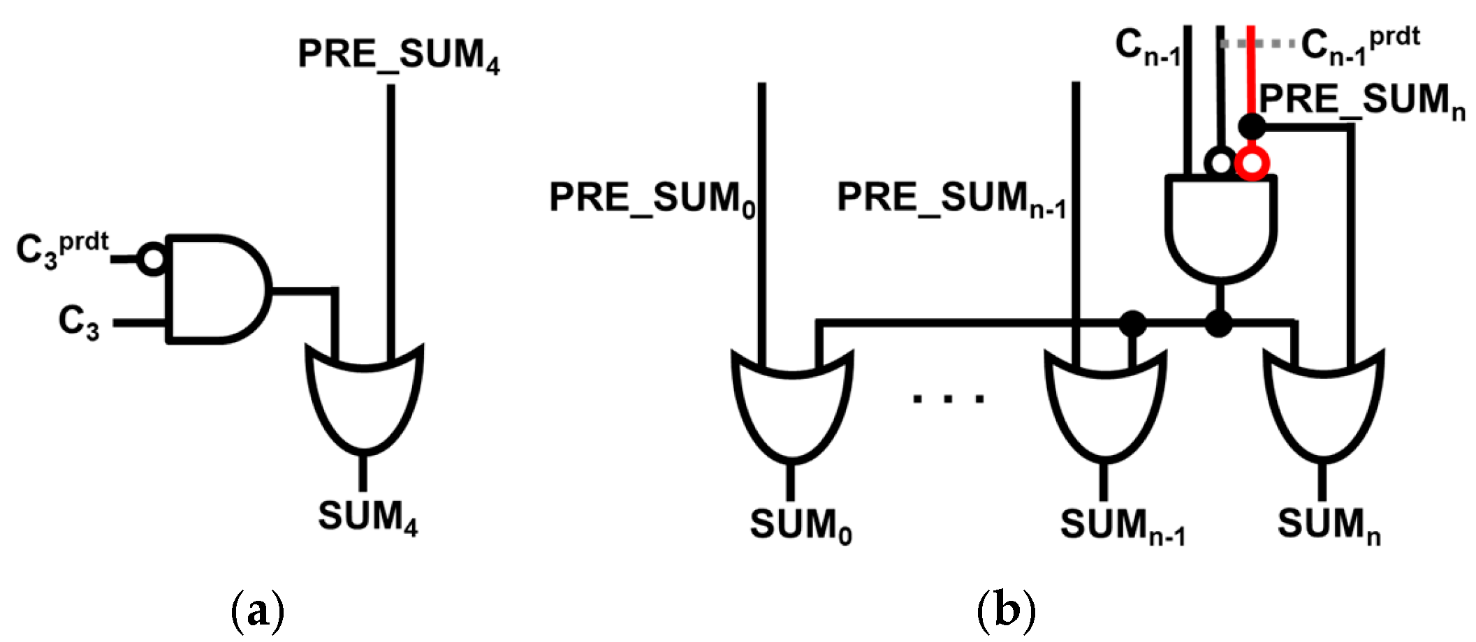
For ERU_plus as shown in Figure 2c, by attaching an ERU to SUM3 as well, big error distances (ED) are removed which makes errors smaller than in ERU_simple (i.e., single bit correction). Furthermore, ERU_max, as demonstrated in Figure 2d, by attaching ERUs to all the lower 5 bits, we can observe a decrease in MED by 51% compared to the 8-bit DCFA w/o ERU. As the ERU becomes more complex, it is observed that the calculation time for SUM4 progressively increases. A detailed structure of the ERU is illustrated in Figure 3.
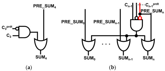
Figure 3.
Proposed ERU design for (a) single bit correction, and (b) multi-bit correction.
2.2. Application of DCAA in Wallace Tree Multiplier
2.2.1. Wallace Tree Multiplier Architecture and Proposed Methodology
The Wallace Tree multiplier structure efficiently reduces the number of partial products in multiplication. The Wallace Tree operates by first generating the partial products, followed by compressing them through multiple stages of addition using full adders and half adders. This process continues until the partial products are reduced to two final sums. In the final stage, these two partial sums need to be added to produce the final result. For this purpose, several adders were applied in the summation step, including both existing and proposed models. The final addition plays a crucial role in determining the delay and overall performance of the multiplier.
2.2.2. Adder Integration in the Summation Stage
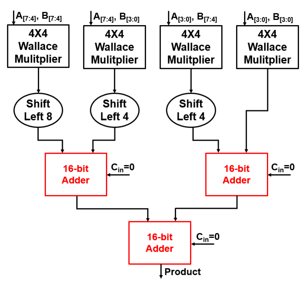
In the summation stage of the multiplier, various adder models were applied to compare performance. Before the addition process begins, each 4 × 4 Wallace multiplier in the 8 × 8 multiplier generates partial products. These partial products must be aligned to their respective place values through left shifting. Specifically, the partial products from the upper-left 4 × 4 multiplier are shifted left by 8 bits, while those from the upper-right 4 × 4 multiplier are shifted left by 4 bits. The partial products from the two lower 4 × 4 Wallace multipliers are not shifted. After this alignment, the summation process is carried out using three 16-bit adders. The first adder sums the shifted outputs from the two left-side 4 × 4 multipliers, and the second adder sums the outputs from the two right-side 4 × 4 multipliers. Finally, a third 16-bit adder is used to combine the results from the first two adders, producing the final product. This multi-stage addition ensures that the partial products are correctly aligned and summed, optimizing the multiplication process.
In this addition process, various 16-bit adder structures were experimentally applied. The 16-bit adders are applied to the three red-highlighted sections of the 8 × 8 Wallace multiplier, as shown in Figure 4. Each addition stage in the 8 × 8 multiplier used 16-bit RCA, 16-bit SARA, 16-bit DCAA w/o ERU, and 16-bit DCAA w/ERU_max structures for comparison. Figure 5 illustrates the structure of the 16-bit DCAA, highlighting the critical path in red. Through these experiments, we analyzed the performance differences of each adder structure to determine the optimal design in terms of delay, accuracy, and power consumption.
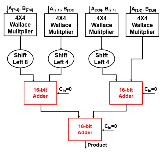
Figure 4.
Overall structure of 8 8 Wallace multiplier.
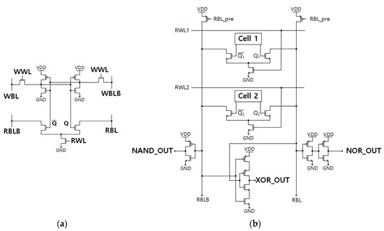
Figure 5.
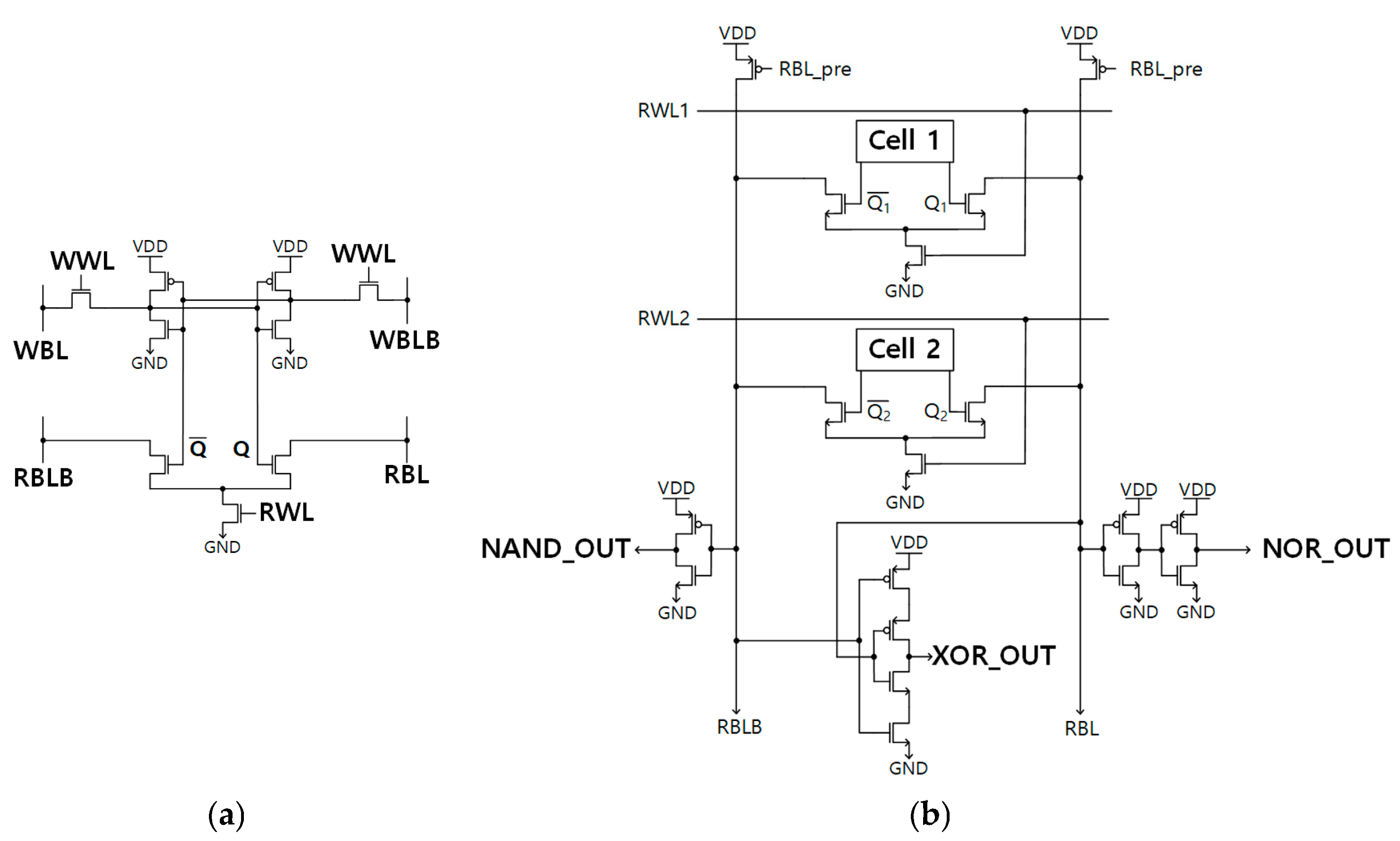
(a) 8+T Differential SRAM cell [7], (b) 8+T Differential SRAM-based IMC circuit [8].
2.3. Application of DCAA in In-Memory Computing (IMC)
2.3.1. Conventional 8-Bit IMC Approximate Adder
Both the 1-bit IMC FA and the 1-bit IMC approximate adder are composed of an 8+T Differential SRAM-based IMC circuit along with additional gates. Two 8+T Differential SRAM cells (as depicted in Figure 5a), inverters, and a 2-input Muller C-element constitute the 8+T Differential SRAM-based IMC circuit, which is illustrated on Figure 5b. Initially, nodes RBL and RBLB are pre-charged to ‘1’. When two words are simultaneously selected, the circuit produces the outputs of NAND, NOR, and XOR, depending on the value of the node Q1, Q2, as detailed in [8].
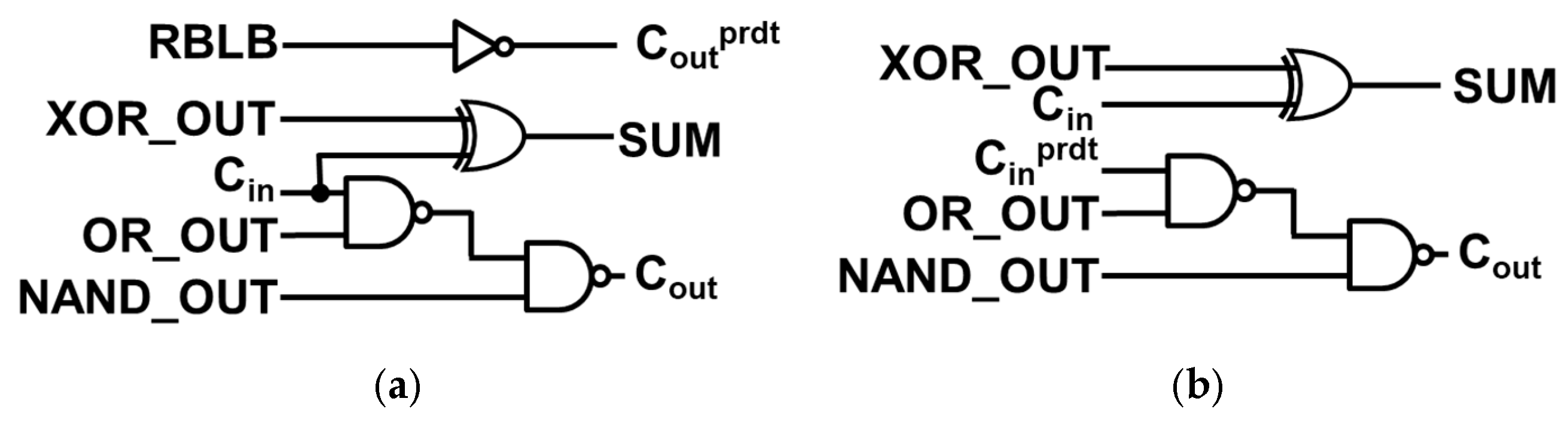
The 1-bit IMC FA is realized by integrating additional logic gates with the logic outputs (NAND_OUT, OR_OUT, and XOR_OUT) in the 8+T Differential SRAM-based IMC circuit. Figure 6a illustrates the specific additional logic gates selected for the 1-bit IMC FA. The computations of the 1-bit IMC FA are expressed by (1) and (2). The 1-bit IMC approximate adder [9,10,11,12,13,14,15] follows a similar implementation method, but it diverges in terms of the additional logic gates connected to the logic outputs within the 8+T Differential SRAM-based IMC circuit, as depicted in Figure 5b. In this case, approximate adder AFA3 [4] has been implemented to the 8+T Differential SRAM-based IMC circuit.
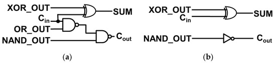
Figure 6.
Additional gates for (a) 1-bit IMC FA and (b) 1-bit IMC approximate adder.
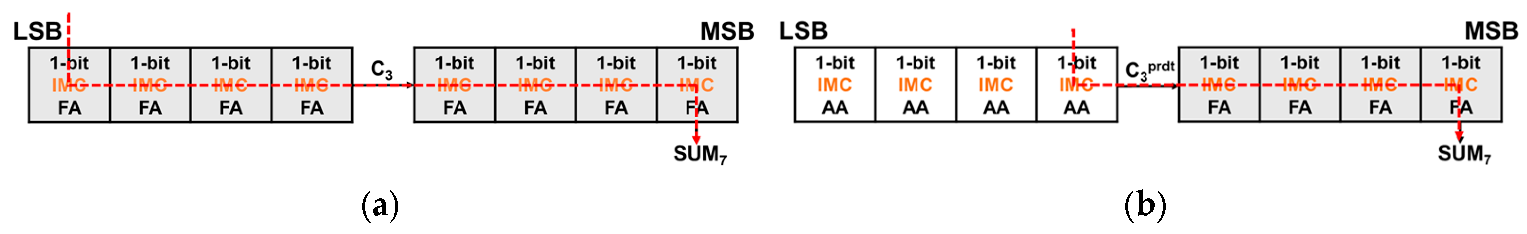
Equation (1) represents the sum computation for the 1-bit IMC approximate adder, which remains consistent with that of the 1-bit IMC FA. However, Equation (3), which represents the carry computation of both AFA3 and the 1-bit IMC approximate adder, reveals that the carry computation in the 1-bit IMC approximate adder differs from that of the conventional FA. Consequently, certain cases may introduce errors. For example, when the carry-in is 1 and A⊕B = 1, the accurate carry-out should be 1, but the approximate carry-out becomes 0. Figure 7 illustrates the overall structure of the conventional 8-bit IMC ripple carry adder (RCA) and 8-bit IMC approximate adder, as previously studied. The red line illustrates the critical path of both adders. The 8-bit IMC approximate adder comprises a 1-bit IMC FA for the higher 4 bits and a 1-bit IMC approximate adder for the lower 4 bits. Since each lower 4-bit is an independent computer, it offers faster performance than the 8-bit IMC RCA. However, its accuracy is compromised due to the inability to correct errors resulting from approximation, as explained in [9].
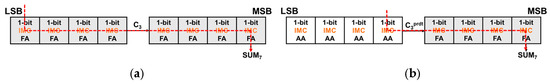
Figure 7.
Overall structure of (a) conventional 8-bit IMC RCA, (b) conventional 8-bit IMC approximate adder (with red dashed line indicating critical paths).
2.3.2. Proposed 8-Bit Dual Carry IMC Approximate Adder
Dual carry-out IMC FA and dual carry-in IMC FA are akin to the 1-bit IMC FA, with additional logic gates attached to the 8+T Differential SRAM-based IMC circuit, as depicted in Figure 5b.
Dual carry-out IMC FA outputs both a precise carry (Cout) and a predicted carry (Coutprdt), like the carry-out selectable FA of SARA [3]. Equations (1)–(3) present the three outputs of this adder. Figure 8a showcases the additional gates for the Dual carry-out IMC FA, with a buffer being added in comparison to the 1-bit IMC FA.
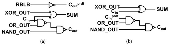
Figure 8.
Additional gates for (a) Dual carry-out IMC FA and (b) Dual carry-in IMC FA.
In contrast, the dual carry-in IMC FA receives both a precise carry (Cin) and a predicted carry (Cinprdt), which are computed by the dual carry-out IMC FA. This is like the carry-in configurable FA of SARA that receives two carries. However, the distinguishing factor is that the dual carry-in IMC FA consistently uses Cinprdt to compute Cout. Equations (1) and (4) represent the computations of the dual carry-in IMC FA, and Figure 8b illustrates the additional gates for the dual carry-in IMC FA.
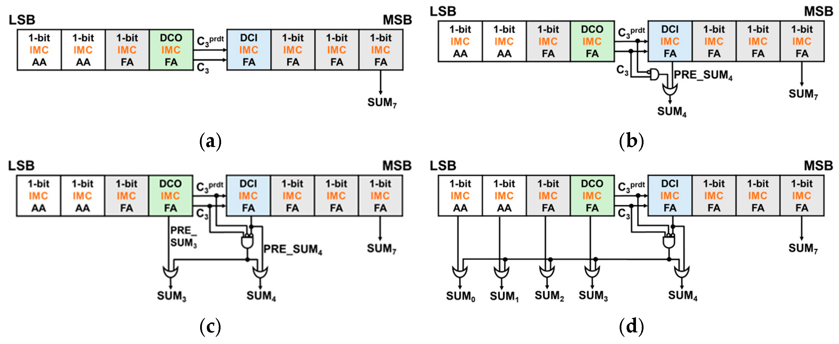
The 8-bit DCAA w/o ERU, which is depicted on Figure 9a, approach eliminates the MUX entirely, unlike SARA [3], enabling the carry chain to speed up by bypassing MUX. Only the C3prdt value is used exclusively for calculating the carry chain, while the exact C3 value is utilized for computing the sum. Although there is a notable improvement in the delay when compared to the 8-bit IMC RCA, the accuracy did not meet the anticipated improvement. This necessitates further exploration into strategies to minimize the error distance (ED).
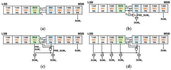
Figure 9.
8-bit DCAA-based approximate adders (with red dashed line indicating critical paths): (a) w/o ERU, (b) w/ERU_simple, (c) w/ERU_plus, and (d) w/ERU_max.
The ERU balances delay reduction and error minimization. Figure 3a illustrates the single-bit correction ERU, applied to the 8-bit DCAA w/ERU_simple (Figure 9b), effectively reducing large ED values such as 36 and 32. Equation (5), introduced in Section 2.1.2, provides the formula for the ERU for single bit correction. ERU for multi bit correction, which is depicted on Figure 3b, requires circuit modifications to prevent excessive correction attempts. Therefore, an additional condition, PRE_SUMn = 0, is introduced. ERUs for multi bit correction are implemented on 8-bit DCAA w/ERU_plus and w/ERU_max to correct SUM4 and lower bits for more precise computation. Figure 9c and 9d illustrate the structures of 8-bit DCAA with ERUs for multi bit correction.
For 8-bit DCAA w/ERU_plus, as shown in Figure 9c, by attaching an ERU to SUM3 as well, large EDs are removed, which results EDs concentrated in smaller values than in 8-bit DCAA w/ERU_simple. Furthermore, 8-bit DCAA w/ERU_max, as demonstrated in Figure 9d, by attaching ERUs to all the lower 5 bits, a decrease in MED by 78% and MRED by 74% compared to the 8-bit DCAA w/o ERU can be observed.
3. Results
The integration of the Error Reduction Unit (ERU) into the Dual Carry Approximate Adder (DCAA) demonstrated a significant reduction in error compared to conventional approximate adders. When applied to multipliers and in-memory computing (IMC) architectures, the DCAA with ERU achieved lower Mean Error Distance (MED), Mean Relative Error Distance (MRED), and error rate (ER), while maintaining comparable performance in terms of delay and power efficiency.
MED and MRED were calculated using the absolute difference between the exact output and the approximate output for all test cases. For MRED, the error distance was normalized by the exact output. These metrics are widely used and validated in the field of approximate computing to quantitatively evaluate the trade-off between accuracy and efficiency, thus serving as reliable indicators for performance validation [4].
3.1. Performance Comparison of DCAA with Conventional Adders
Table 1 compares the error metrics of different 8-bit approximate adders. The 8-bit approximate adder(4:4) shows the highest MED, MRED, and error rate (ER) due to its lack of error correction. The 8-bit approximate adder(3:5) and 8-bit SARA show lower error metrics. The 8-bit DCFA variants, especially with ERUs, demonstrate lower MED than the 8-bit SARA, and a 15% lower ER compared to the 8-bit approximate adder(4:4).

Table 1.
Comparison of errors in different 8-bit approximate adders.
Table 2 presents a comparison of delay, power consumption, and area among different 8-bit adders. The ERU_plus and ERU_max increase the delay by about 3% compared to ERU_simple, but significantly reduce MRED. Despite an 8% larger area for ERU_max compared to the 8-bit RCA, the power consumption is 2% less.
Table 2.
Comparative analysis of delay, total power consumption, total area between different 8-bit adders.
When high speed, low power consumption, and area efficiency are prioritized over accuracy, DCFA w/o ERU and DCFA w/ERU_simple can be selected. If higher accuracy is required at the cost of slight performance degradation, DCFA w/ERU_plus is a suitable option. Finally, when maximum accuracy is essential, even at the expense of increased power and area, DCFA w/ERU_max can be chosen. While the authors mention that the 1-bit IMC approximate adder introduces errors in certain cases, it would be beneficial to include more quantitative analysis or examples of error rates in different conditions or workloads.
3.2. Performance Evaluation of Wallce Tree Multipliers with DCAA
3.2.1. Data Analysis
In the summation stage of the Wallace multiplier, performance evaluation was centered around delay, power consumption, and area. The performance metrics, including Mean Error Distance (MED), Mean Relative Error Distance (MRED), and Error Rate (ER), were evaluated and are summarized in Table 3. The figure of merit (FoM) in Table 4 was calculated by multiplying the delay, power, area, and MED of each 8 × 8 multiplier, providing a single metric that reflects both performance and accuracy. The multiplier using DCAA w/o ERU achieved the shortest delay of 1.42 ps, which is 32% faster than the multiplier using RCA’s delay of 2.09 ps. This significant improvement is attributed to the approximate nature of the DCAA, by eliminating long carry chains through carry prediction.
Table 3.
Comparison of errors in 8 8 multipliers using different approximate adders.
Table 4.
Comparative analysis of delay, total power consumption, and total area between 8 8 multipliers using different approximate adders.
The multiplier using DCAA w/ERU_max exhibited a slightly longer delay of 1.68 ps, yet it still outperformed the RCA by 19.7%, demonstrating efficient error correction without incurring substantial delay. While the multiplier using SARA model exhibited a delay of 1.74 ps, the multiplier using DCAA w/o ERU was 18.4% faster, and the multiplier using DCAA w/ERU_max showed a 3.4% improvement. In terms of power consumption and area, both multipliers using DCAA models demonstrated comparable efficiency. The multiplier using DCAA w/o ERU consumed 394 μW and occupied an area of 851.63 μm2, while the multiplier using DCAA w/ERU_max consumed 452.1 μW and required 949.27 μm2 of area.
These results highlight that the multipliers using DCAA models, even with error correction mechanisms in place, maintain competitive power and area metrics compared to the multiplier using SARA, while offering superior delay performance.
3.2.2. Image Processing Analysis
In an 8-bit greyscale image, each pixel is represented by a value ranging from 0 to 255. To evaluate the performance of various approximate multipliers, image blending techniques were employed. These multipliers are utilized to multiply the pixel values located at corresponding positions in each image. The image quality is inferred by comparing the average Peak Signal-to-Noise Ratio (PSNR) of the adders.
Four blending scenarios—Lena with Airplane, Goldhill with Airplane, Man with Sailboat, and Man with Zelda—were executed for each approximate multiplier to determine the average PSNR results are presented in Figure 10. As indicated in Table 5, the average PSNR for the 8 × 8 approximate multiplier escalates with the implementation of the ERU. Notably, the multiplier using DCAA w/ERU_max exhibits the highest average PSNR among the multipliers.
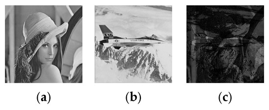
Figure 10.
Example of image blending. (a) First input (Lena), (b) second input (Airplane), and (c) resulting blended image demonstrating the effectiveness of the DCAA-based multiplier in merging pixel values from both images.
Table 5.
Comparison of average PSNR in different 8 8 multipliers.
3.3. Performance Analysis of IMC Architecture with DCAA
3.3.1. Data Analysis
0000 0000 + 0111 1111 = 0111 1111
Equation (6) presents the computation for the worst-case scenario involving seven different 8-bit IMC Adders: 8-bit IMC RCA, 8-bit IMC approximate adder: (m = 4, n = 4) and (m = 3, n = 5), 8-bit DCAA w/o ERU, w/ERU_simple, ERU_plus, and ERU_max. Here, ‘m’ denotes the number of lower bits where the 1-bit IMC approximate adder is used, and ‘n’ signifies the number of higher bits where the 1-bit IMC FA is used. The computational results are consistent across all these adders.
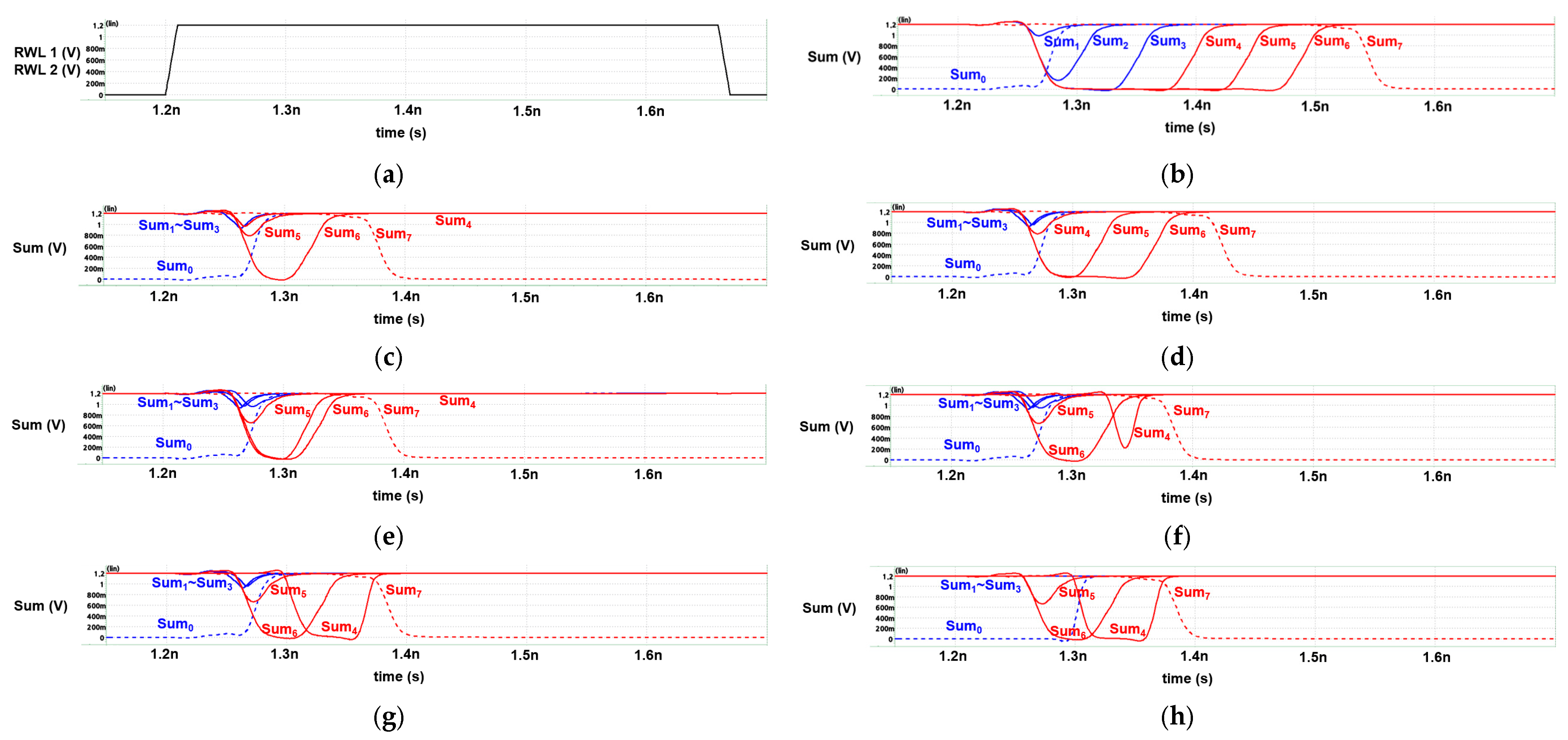
In Figure 11, the red line signifies the sum of the upper four bits, while the blue line represents the sum of the lower four bits. The highest bit’s sum is represented by a dotted line due to its output differing from the other bits. Similarly, the lowest bit’s sum is also represented by a dotted line, as its initial value differs from the other bits. Figure 11a illustrates two RWLs of all IMC adders.
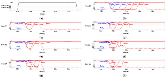
Figure 11.
Timing graph of (a) Read Word Line (RWL) of every IMC approximate adder, (b) sum of 8-bit IMC RCA, (c) sum of 8-bit IMC approximate adder(4:4), (d) sum of 8-bit IMC approximate adder(3:5), (e) sum of 8-bit DCAA w/o ERU, (f) sum of 8-bit 8-bit DCAA w/ERU_simple, (g) sum of 8-bit DCAA w/ERU_plus, and (h) sum of 8-bit DCAA w/ERU_max.
After the RBL and RBLB nodes are pre-charged, the initial carry-in of the 2nd to 8th bit (C1~C7) is set to “high” for all three adders. This contrasts with the initial carry-in of the lowest bit (C0), which is set to “low”. Consequently, the initial sum of the lowest bit differs from the other bits, as explained in [9].
According to Figure 11, the 8-bit IMC approximate adder(4:4) is the fastest among the seven adders, as it employs approximate adders on the lower four bits. Conversely, the 8-bit IMC approximate adder(3:5) is 27% slower than the 8-bit IMC approximate adder(4:4), as per Table 6. This is attributed to its longer critical path, which results from the additional use of a 1-bit IMC FA instead of a 1-bit IMC approximate adder.
Table 6.
Comparison of delay, total energy consumption, and total number of transistors among different 8-bit IMC adders.
Table 6 presents a comparison of delay, total energy consumption, and total number of transistors among different 8-bit adders. For DCAA variants, 4% of delay was increased when compared to 8-bit IMC approximate adder(4:4). However, they had 47%, 18% less delay when compared to 8-bit IMC RCA, 8-bit IMC approximate adder(3:5), respectively. Total power consumption and total number of transistors increased among DCAA variants as ERU intensifies from ERU_simple to ERU_max, but they still consumed less total energy than 8-bit IMC RCA.
Table 7 compares the error metrics of different 8-bit approximate adders. For 8-bit SARA, detection window of 1 bit is used. The 8-bit IMC approximate adder(4:4) shows the highest MED, MRED, and ER due to its extensive use of approximate adders and lack of error correction. The 8-bit DCAA with ERUs, demonstrates lower MED and MRED than the 8-bit SARA, and a 41% lower ER compared to the 8-bit IMC approximate adder(4:4). Especially, MED was reduced by 78%, MRED by 74% on 8-bit DCAA w/ERU_max.
Table 7.
Comparison of errors in different 8-bit IMC approximate adders.
3.3.2. Image Processing Analysis
In an 8-bit greyscale image, each pixel is represented by a value ranging from 0 to 255. To evaluate the performance of various approximate adders, image blending techniques were employed. These adders are utilized to sum up the pixel values located at corresponding positions in each image. The image quality is inferred by comparing the average Peak Signal-to-Noise Ratio (PSNR) of the adders.
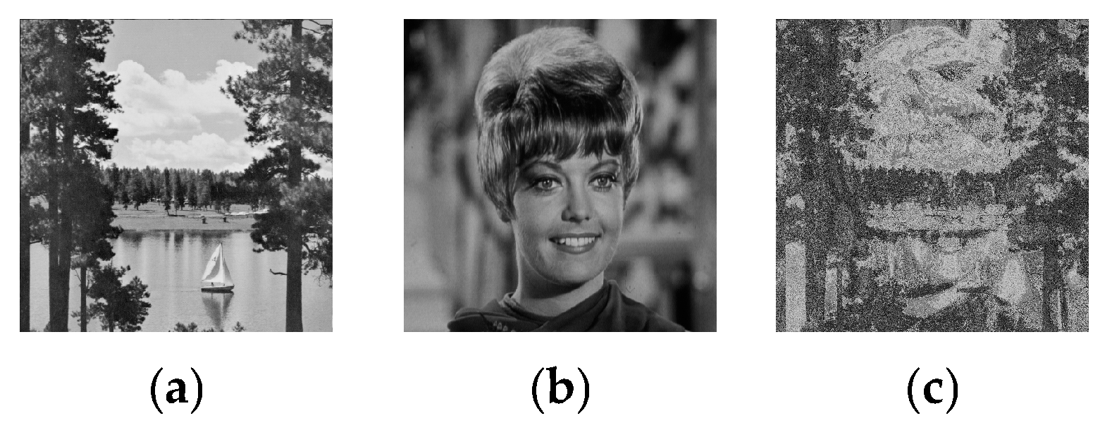
Five blending scenarios—Sailboat with Zelda, Sailboat with Man, Zelda with Man, Zelda with Goldhill, and Sailboat with Goldhill—were executed for each IMC approximate adder to determine the average PSNR results as shown in Figure 12. As indicated in Table 8, the average PSNR for the 8-bit DCAA escalates with the intensification of the ERU from ERU_simple to ERU_max. Notably, the 8-bit DCAA w/ERU_max exhibits the highest average PSNR among the 8-bit IMC approximate adders.

Figure 12.
Example of image blending. (a) Sailboat image as first input, (b) Zelda image as second input, and (c) resulting blended image demonstrating effectiveness of our method in merging pixel values from both images.
Table 8.
Comparison of average PSNR in different 8-bit IMC adders.
4. Discussion
One limitation of the proposed DCAA is the increase in area and power caused by the inclusion of ERUs. However, this trade-off is justified by the significant reduction in error metrics while maintaining comparable speed. When applying ERU_max, the delay is reduced by 3.5% and the Mean Error Distance (MED) is decreased by 77.7% compared to the conventional 8-bit IMC approximate adder(4:4) [9], indicating a substantial scientific advancement. However, in terms of power and area, the ERU_max design exhibits a 21.8% increase in energy consumption and an 18.3% increase in the total number of transistors. These drawbacks will be addressed in future studies to further optimize the design.
In particular, the Wallace Tree multiplier, when utilizing DCAA with ERU_max, achieves an effective balance between speed, efficiency, and accuracy, making it highly suitable for high-performance applications. Similarly, the IMC architectures integrated with DCAA demonstrate enhanced accuracy compared to conventional 8-bit IMC approximate adders, while preserving speed levels comparable to the original designs. These findings highlight the potential of DCAA to significantly improve computational accuracy across various applications without substantial compromises in performance.
5. Conclusions
The Dual Carry Approximate Adder (DCAA) is an enhanced 8-bit approximate adder designed with advanced error recovery structures, including dual carry-out and dual carry-in full adders (FAs). Despite a slight increase in area and power due to the implementation of ERUs, the DCAA achieves substantial reductions in error metrics, with MED reduced by 51%, MRED by 50%, and ER by 15%, while maintaining comparable speed.
The proposed DCAA designs were designed at the RTL level using Verilog using Vivado. Based on the schematic shown in Figure 9, other researchers can replicate our RTL design and verify functionality. While the proposed DCAA designs show notable improvements, all evaluations were based on synthesis using the 45 nm Nangate Open Cell Library with Synopsys Design Compiler, prior to place-and-route. Actual tape-out may result in increased delay and power due to routing overhead and process variations. And HSPICE was used to perform transistor-level simulations to verify power and delay characteristics under typical operating conditions.
However, if the proposed designs were to be fabricated using emerging device technologies such as CNTFETs or GNRFETs, the delay and power consumption are expected to further improve due to the superior electrical characteristics of these devices compared to conventional 45 nm CMOS technology.
When applied to the summation stage of the Wallace Tree multiplier, the DCAA without ERU demonstrated the shortest delay, outperforming RCA by 32%. Meanwhile, the DCAA with ERU_max effectively balanced speed and accuracy with only a minimal increase in delay. Both configurations exhibited comparable power and area efficiency to other adders, such as SARA, indicating that the inclusion of error correction in DCAA does not impose significant resource overhead. Moreover, the multiplier utilizing DCAA with ERU_max achieved the highest PSNR, underscoring its superior error correction capabilities.
To enhance the accuracy of conventional 8-bit IMC approximate adders, this study proposes four novel structures. Each of these designs incorporates both dual carry-out and dual carry-in IMC FAs, enabling precise and predicted carry operations. The development process of these structures’ spans from the most fundamental designs to the most precise configurations, with ERUs integrated to further reduce error metrics. As a result, the proposed designs are significantly lower MED, MRED, and ER compared to conventional IMC adders, while maintaining speeds nearly identical to the original designs. Notably, the 8-bit DCAA with ERU_simple strikes a remarkable balance in accuracy, delay, energy efficiency, and resource usage, achieving significant reductions in both MED and MRED.
In future work, the proposed approximate adder designs may be extended to higher bit-width architectures such as 32-bit or 64-bit multipliers and applied to other arithmetic units like the addition stages of dividers. Furthermore, we aim to explore their integration into larger computing architectures, including CPUs and AI accelerators, where approximate computing can contribute to enhanced energy efficiency and performance.
In addition, given that our adder architecture achieves low error rates at the expense of increased power consumption, we plan to design energy-efficient adders by integrating an ERU to further optimize power usage.
Author Contributions
Conceptualization, J.K. and Y.K.; methodology, J.K. and E.K.; software, K.L. and J.K.; validation, K.L., E.K. and J.K.; formal analysis, J.K.; investigation, K.L.; resources, Y.K.; data curation, K.L. and J.K.; writing—original draft preparation, K.L. and E.K.; writing—review and editing, Y.K.; visualization, K.L.; supervision, Y.K.; project administration, Y.K.; funding acquisition, Y.K. All authors have read and agreed to the published version of the manuscript.
Funding
This research was supported by the Ministry of Science and ICT (MSIT), Republic of Korea.
Data Availability Statement
All data underlying the results are available as part of the article and no additional source data are required.
Acknowledgments
This research was supported by the MSIT (Ministry of Science and ICT), Korea, under the ITRC (Information Technology Research Center) support program (IITP-2025-RS-2022-00156225) supervised by the IITP (Institute for Information & Communications Technology Planning & Evaluation). The EDA tool was supported by the IC Design Education Center (IDEC), Korea.
Conflicts of Interest
The authors declare no conflicts of interest.
References
- Vendhan, A.; Ahmed, S.E.; Gurunarayanan, S. Design of Approximate Adder with Reconfigurable Accuracy. IEEE Access 2025, 13, 17030–17042. [Google Scholar] [CrossRef]
- Wu, Y.; Chen, C.; Xiao, W.; Wang, X.; Wen, C.; Han, J.; Yin, X.; Qian, W.; Zhuo, C. A Survey on Approximate Multiplier Designs for Energy Efficiency: From Algorithms to Circuits. ACM Trans. Des. Autom. Electron. Syst. 2025, 29, 1–37. [Google Scholar] [CrossRef]
- Xu, W.; Sapatnekar, S.S.; Hu, J. A Simple Yet Efficient Accuracy-Configurable Adder Design. IEEE Trans. Very Large Scale Integr. (VLSI) Syst. 2018, 26, 1112–1125. [Google Scholar] [CrossRef]
- Dutt, S.; Nandi, S.; Trivedi, G. Analysis and Design of Adders for Approximate Computing. ACM Trans. Embed. Comput. Syst. 2018, 17, 40. [Google Scholar] [CrossRef]
- Seo, H.; Kim, Y. A Low Latency Approximate Adder Design Based on Dual Sub-Adders with Error Recovery. IEEE Trans. Emerg. Top. Comput. 2023, 11, 811–816. [Google Scholar] [CrossRef]
- Ebrahimi-Azandaryani, F.; Akbari, O.; Kamal, M.; Afzali-Kusha, A.; Pedram, M. Block-Based Carry Speculative Approximate Adder for Energy-Efficient Applications. IEEE Trans. Circuits Syst. II Express Briefs 2020, 67, 137–141. [Google Scholar] [CrossRef]
- Kulkarni, J.P.; Goel, A.; Ndai, P.; Roy, K. A Read-Disturb-Free, Differential Sensing 1R/1W Port, 8T Bitcell Array. IEEE Trans. Very Large Scale Integr. (VLSI) Syst. 2011, 19, 1727–1730. [Google Scholar] [CrossRef]
- Song, S.; Kim, Y. Novel In-Memory Computing Circuit Using Muller C-Element. In Proceedings of the 18th International SoC Design Conference (ISOCC), Jeju Island, Republic of Korea, 6–9 October 2021; pp. 81–82. [Google Scholar] [CrossRef]
- Song, S.; Kim, Y. Novel In-Memory Computing Adder Using 8+T SRAM. Electronics 2022, 11, 929. [Google Scholar] [CrossRef]
- Seo, H.; Yang, Y.S.; Kim, Y. Design and Analysis of an Approximate Adder with Hybrid Error Reduction. Electronics 2020, 9, 471. [Google Scholar] [CrossRef]
- Hu, J.; Qian, W. A New Approximate Adder with Low Relative Error and Correct Sign Calculation. In Proceedings of the Design, Automation & Test in Europe Conference & Exhibition (DATE), Grenoble, France, 9–13 March 2015; pp. 1449–1454. [Google Scholar]
- Yantir, H.E.; Eltawil, A.M.; Kurdahi, F.J. Approximate Memristive In-Memory Computing. ACM Trans. Embed. Comput. Syst. 2017, 16, 1–18. [Google Scholar] [CrossRef]
- Kumar, V.; Singh, A.; Upadhyay, S.; Kumar, B. Power–Delay–Error-Efficient Approximate Adder for Error-Resilient Applications. J. Circuits Syst. Comput. 2019, 28, 1950171. [Google Scholar] [CrossRef]
- Balasubramanian, P.; Nayar, R.; Maskell, D. An Approximate Adder with Reduced Error and Optimized Design Metrics. In Proceedings of the 2021 IEEE Asia Pacific Conference on Circuits and Systems (APCCAS), 22–26 November 2021; pp. 315–318. [Google Scholar] [CrossRef]
- Dalloo, A.; Najafi, A.; Garcia-Ortiz, A. Systematic Design of an Approximate Adder: The Optimized Lower Part Constant-OR Adder. IEEE Trans. Very Large-Scale Integr. (VLSI) Syst. 2018, 26, 1595–1599. [Google Scholar] [CrossRef]


Disclaimer/Publisher’s Note: The statements, opinions and data contained in all publications are solely those of the individual author(s) and contributor(s) and not of MDPI and/or the editor(s). MDPI and/or the editor(s) disclaim responsibility for any injury to people or property resulting from any ideas, methods, instructions or products referred to in the content. |
© 2025 by the authors. Licensee MDPI, Basel, Switzerland. This article is an open access article distributed under the terms and conditions of the Creative Commons Attribution (CC BY) license (https://creativecommons.org/licenses/by/4.0/).