Article

A New Study on the Temperature and Bias Dependence of the Kink Effects in S22 and h21 for the GaN HEMT Technology

1
Department of Biomedical and Dental Sciences and Morphofunctional Imaging, University of Messina, 98125 Messina, Italy
2
Department of Engineering, University of Ferrara, 44122 Ferrara, Italy
3
Department of Engineering, University of Messina, 98166 Messina, Italy
*
Author to whom correspondence should be addressed.
Electronics 2018, 7(12), 353; https://doi.org/10.3390/electronics7120353
Submission received: 16 October 2018 / Revised: 12 November 2018 / Accepted: 21 November 2018 / Published: 25 November 2018
(This article belongs to the Section Microelectronics)

Abstract

:
The aim of this feature article is to provide a deep insight into the origin of the kink effects affecting the output reflection coefficient (S22) and the short-circuit current-gain (h21) of solid-state electronic devices. To gain a clear and comprehensive understanding of how these anomalous phenomena impact device performance, the kink effects in S22 and h21 are thoroughly analyzed over a broad range of bias and temperature conditions. The analysis is accomplished using high-frequency scattering (S-) parameters measured on a gallium-nitride (GaN) high electron-mobility transistor (HEMT). The experiments show that the kink effects might become more or less severe depending on the bias and temperature conditions. By using a GaN HEMT equivalent-circuit model, the experimental results are analyzed and interpreted in terms of the circuit elements to investigate the origin of the kink effects and their dependence on the operating condition. This empirical analysis provides valuable information, simply achievable by conventional instrumentation, that can be used not only by GaN foundries to optimize the technology processes and, as a consequence, device performance, but also by designers that need to face out with the pronounced kink effects of this amazing technology.

Graphical Abstract

1. Introduction

With the aim of enabling microwave engineers to exploit advanced transistor technologies at their best, increasing attention is being given to the investigation of the kink effects in the output reflection coefficient (S22) and the short-circuit current-gain (h21) of solid-state electronic devices made with different semiconductor materials, like silicon (Si), gallium arsenide (GaAs), and gallium nitride (GaN) [1,2,3,4,5,6,7,8,9,10,11,12,13]. The kink in S22 consists in the change of the concavity of the function Im(S22) versus Re(S22) (i.e., from convex to concave and vice versa), while the kinks in h21 consist of peaks that are detectable by plotting the magnitude of h21 in dB versus the frequency on a log scale. As the kink effects can be interpreted in terms of the transistor equivalent-circuit elements, many studies have been developed to identify those ones playing a dominant role, depending on the specific case study. The origin of the kink effect in S22 has been mostly ascribed to high values of the transconductance (gm) [1,4,5,6], whereas h21 can be affected by a first kink, originating from the resonance between the extrinsic inductances and the intrinsic capacitances [7,8,9,12,13], and a second kink, arising from the resonance of the extrinsic reactive elements [12,13]. It is worth underlining that an accurate study of the kink effects in S22 and h21 parameters of microwave transistors represents a powerful tool for microwave engineers for fabrication, modeling and design purposes. Device technologists might enhance or alleviate the kinks in S22 and h21, depending on the application constraints, simply through optimization of the device layout and structure. Device modelers can exploit the kinks in S22 and h21 for extracting equivalent circuit parameters (e.g., the resonance frequency associated with the first kink in h21 has been used to accomplish the challenging task of determining the intrinsic output capacitance [7,8]). Circuit designers should properly take into account the kink effect in S22, especially for the design of broadband output matching networks [14,15]. In addition, circuit designers can benefit from the kinks in h21 as they enable achieving an increase in the current gain at the resonant frequencies. However, so far, the interest in obtaining active transistor operation at frequencies beyond the cut-off frequency (fT) has been focused on bipolar transistors (e.g., by proper design of the so-called resonance phase transistor [16,17,18,19,20,21]), recent studies have shown that the achievement of a current gain even at frequencies higher than fT is achievable also in FET transistors, owing to the kinks in h21 [12,13].
This feature article is focused on investigating the kinks in S22 and h21 for the gallium-nitride (GaN) high electron-mobility transistor (HEMT) technology, which is receiving increasing attention for high-temperature and high-power applications at high frequencies [22,23,24,25,26,27,28,29]. In particular, the kinks are studied at different ambient (i.e., case) temperatures (Ta) and bias voltages (VGS and VDS). The study consists of a comprehensive examination of the experimental results based on scattering (S-) parameter measurements and an exhaustive interpretation of the achieved findings using the transistor equivalent-circuit model. Although GaN HEMT is used as a case study, the reported study is technology-independent as it is based on a standard equivalent circuit topology for FETs, thus making the achieved finding representative and generalizable for any FET. This is confirmed by previous studies which have already demonstrated that the appearance or absence of the kinks in S22 and h21 is simply rooted in the values of the equivalent circuit elements of the tested FET, besides the analyzed frequency range [1,6,9,12,13].
The remainder of this article is organized as follows. Section 2 is devoted to the analysis of the kink effect in S22; Section 3 is focused on the investigation of the kink effects in h21; and Section 4 summaries the main conclusions.

2. Kink Effect in S22

The studied solid-state electronic device is a GaN HEMT with a gate length of 0.25 μm and a gate width of 1.5 mm (i.e., 10 × 150 μm) (see Figure 1a). It was manufactured in the GH25-10 technology by United Monolithic Semiconductors (UMS) [30,31,32], using an AlGaN/GaN heterostructure grown on silicon carbide (SiC) substrate with a field plate for power applications. This foundry process, entitling a power density of 4.5 W/mm with typical fT of 25 GHz, is optimized for X-band (i.e., 8–12 GHz) high-power applications. The S-parameters were measured from 0.2 to 65 GHz under different bias conditions and at four ambient temperatures: 35 °C, 90 °C, 145 °C, and 200 °C. Subsequently, the h21 parameter was straightforwardly calculated from the measured S-parameters by using conventional transformation formulas [33]. Figure 1b shows the small-signal equivalent circuit used for modelling the tested transistor. Firstly, the extrinsic elements were determined from S-parameters at “cold” pinch-off condition (i.e., VDS = 0 V and VGS = −4 V) and, subsequently, the intrinsic elements were calculated from the intrinsic admittance (Y-) parameters at each bias point [12].
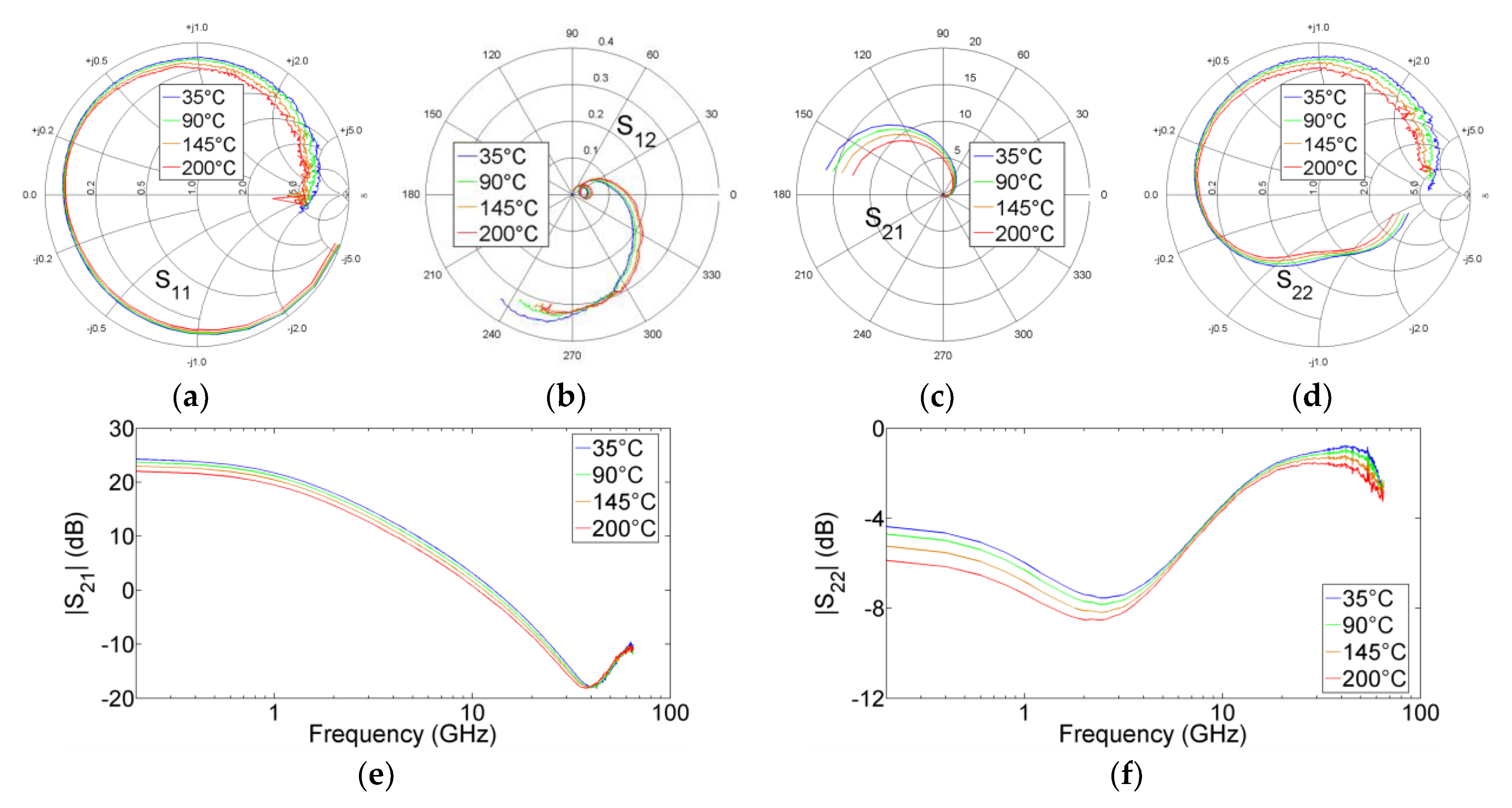
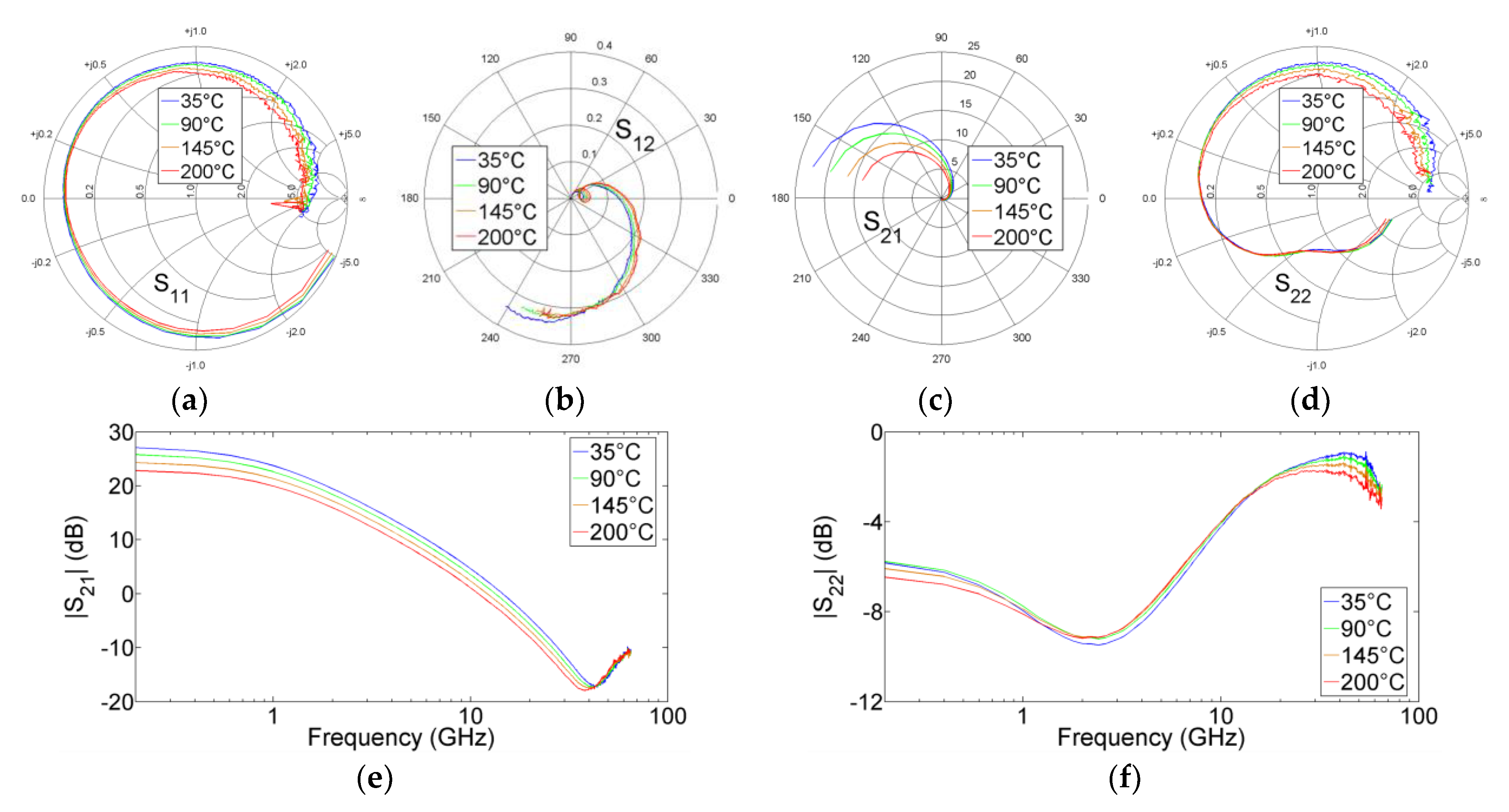
Figure 2 and Figure 3 show the S-parameters measured at the four investigated ambient temperatures with VDS = 30 V and for two values of VGS: −3.5 V and −3.1 V, respectively. It can be observed that S22 of the tested device is affected by the kink effect under both bias conditions. As illustrated in Figure 2f and Figure 3f, the kink effect can be detected also as a dip in the magnitude of S22, due to two zeros occurring between two poles. This is in line with findings from previous studies showing that the kink effect in S22 can be analyzed also in terms of poles and zeros [2,3,4,6]. The shape of the kink effect strongly depends on the combined effects of equivalent circuit elements whose values might remarkably vary with the operating conditions. By heating the device, the kink effect gets less pronounced and this can be attributed to the reduction of gm which is associated to a decrease of the average velocity of the electrons drifting in the 2-D electron gas (2DEG) channel. As a matter of fact, gm plays a dominant role in determining the appearance and the shape of the kink effect in S22. A higher temperature leads also to a decrease in the drain-source resistance (Rds), moving the starting point of S22 closer to the short-circuit condition. By increasing Ta from 35 °C to 200 °C when VGS is −3.5 V, gm and Rds decrease from 225.7 to 186.8 mS and from 189.7 to 146.7 Ω, respectively. Given the same increase in Ta but with VGS = −3.1 V, gm and Rds decrease from 347.9 to 215.4 mS and from 138.9 to 135.2 Ω, respectively.
The reduction of gm and Rds at higher temperatures can be, respectively, noticed from the decrease in the low-frequency magnitudes of the forward transmission (S21) and reflection coefficient S22 (see Figure 2e,f and Figure 3e,f), since at relatively low frequencies S21 and S22 can be linked to gm and Rds as follows [34]:
S 21 = 2 g m E x t r ( R 0 / / R d s E x t r )
S 22 = R d s E x t r R 0 R d s E x t r + R 0
g m E x t r = g m 1 + g m R s + R d s 1 ( R s + R d )
R d s E x t r 1 = R d s 1 1 + g m R s + R d s 1 ( R s + R d )
where R0 is the characteristic resistance (i.e., 50 Ω), while gmExtr and RdsExtr represent the extrinsic transconductance and drain-source resistance.
To focus attention on the VGS dependence, Figure 4 illustrates the S-parameters measured at Ta = 35 °C, VDS = 30 V and with VGS equal to −3.5 V and −3.1 V. By varying VGS from −3.5 to −3.1 V, the improvement of gm leads to an increase of the low-frequency magnitude of S21 and to an enhancement of the kink effect in S22, whereas the decrease of Rds leads to a shift of the starting point of S22 towards the short-circuit condition.
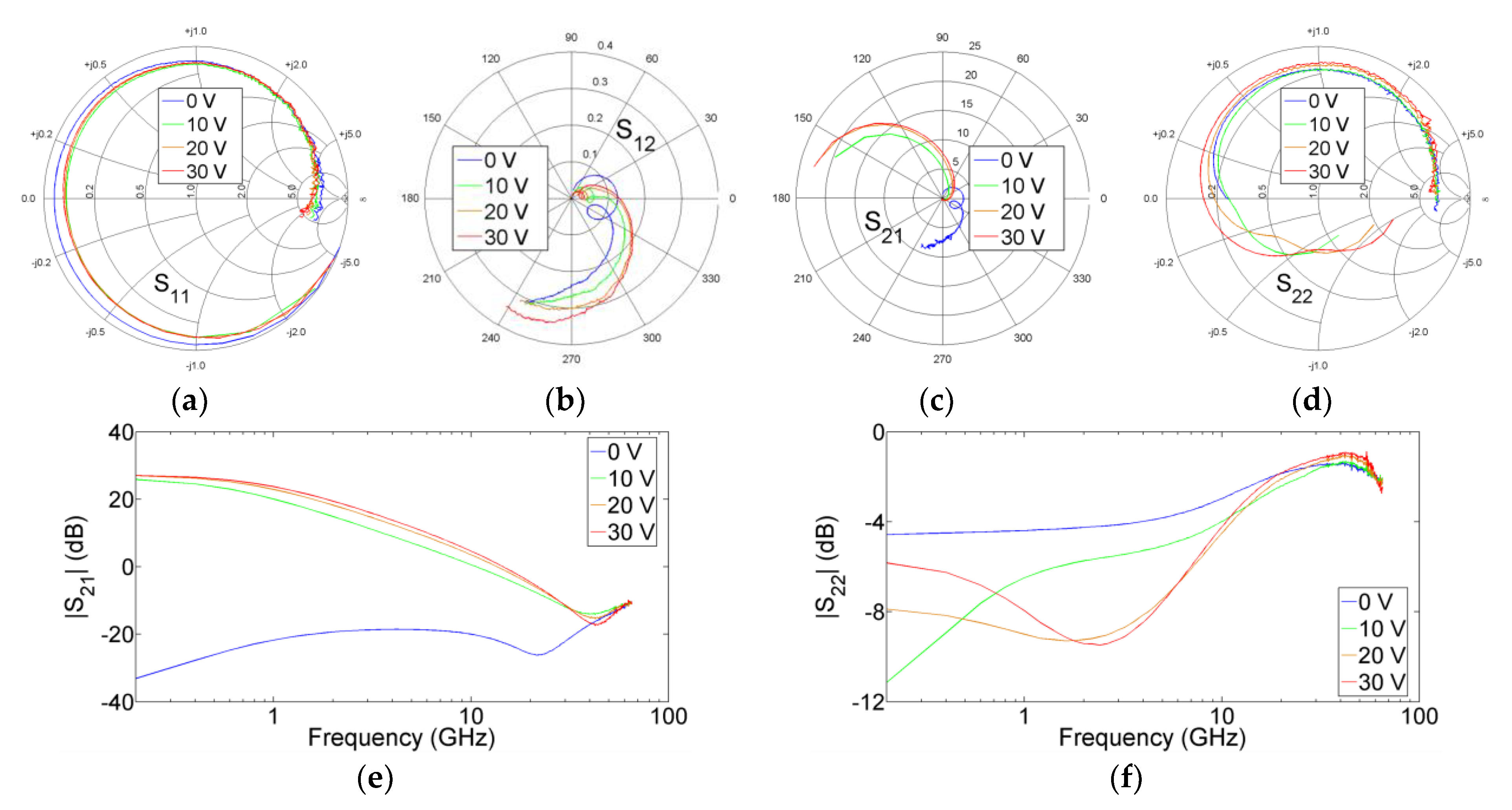
As can be observed in Figure 5, the kink effect in S22 vanishes when VDS reaches 0 V and, in line with this finding, the dip in the magnitude of S22 disappears. This is because, by reducing VDS, gm decreases and, in addition, its role is further diminished by the decrease of Rds. As a matter of fact, Rds is connected in parallel with the voltage-controlled current source (i.e., gmejωπmV) and thus its reduction tends to short circuit the contribution of gm, thereby contributing to the suppression of the kink effect in S22 and to the decrease in the low-frequency magnitude of S21 (see Equation (1)). The reduction of gm and Rds at lower VDS can be, respectively, noticed from the decrease in the low-frequency magnitude of S21 (see Figure 5e) and the shift of the starting point of S22 closer to the short-circuit condition (see Figure 5d).
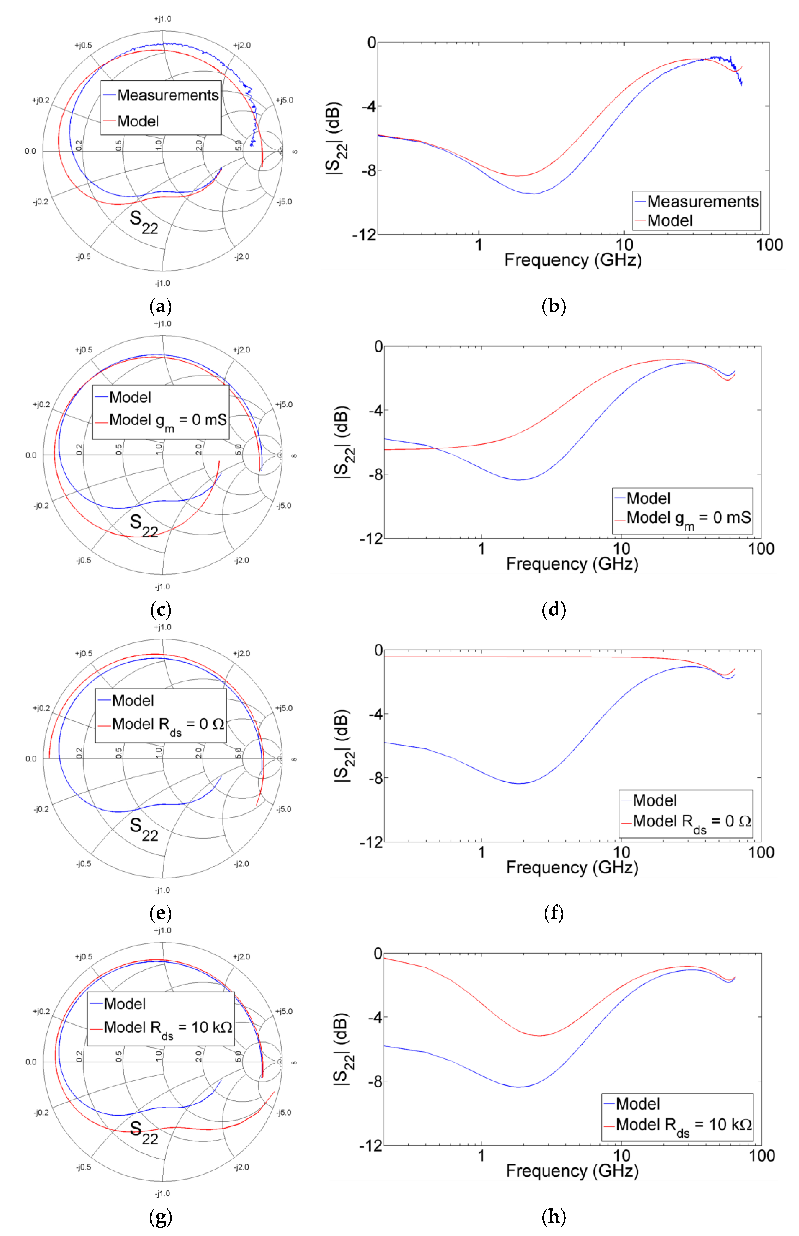
Figure 6a reports the comparison between measured and simulated S22 at Ta = 35 °C, VDS = 30 V, and VGS = −3.1 V. Although the extraction of a model that can faithfully reproduce the behavior of a device with a large gate periphery over a broad frequency range reaching very high frequencies is quite a challenging task, the standard equivalent-circuit model is able to mimic the general trend of the measurements and, in particular, to predict the kink in S22 and the dip in its magnitude too (see Figure 6b). Furthermore, as will be seen in the next section, the extracted model also allows the prediction of the two kinks in h21. It is worth noticing that, in accordance with what is stated above, the kink effect in the simulated S22 can be suppressed by reducing gm and/or Rds (see Figure 6c–f). This is because S22 becomes kink-free by nullifying the value of gm and/or its contribution. On the other hand, by increasing Rds at a very high value, the shape of S22 is modified somewhat and the starting point of S22 shifts towards the open-circuit condition but with the kink effect still affecting S22 (see Figure 6g,h). It is worth noticing that although changing only one element of the model might be not physically representative of a real device, repeating this type of analysis enables understanding of how each element impacts on the appearance and shape of the kinks and the physical soundness of the achieved outcomes is guaranteed by the fact that the equivalent-circuit model is a physically meaningful representation of the FET behavior. As an example, this type of powerful analysis has been conducted in a pioneering study to explore the origin of the kink effect in S22 by varying the intrinsic element values, showing that gm plays a dominant role [1].
As is well known, the most popular technique for determining the extrinsic circuit elements for FETs is based on using S-parameters measured under “cold” conditions (VDS = 0 V, i.e., passive device) [35,36,37,38,39]. As there are no electrons drifting from source to drain when VDS = 0 V, gm is equal to zero, thus implying that S21 becomes equal to S12 and S22 turns out to be kink-free. This is illustrated in Figure 7, showing S-parameters measured at two typical bias points used for modeling purpose: “cold” unbiased (i.e., VGS = 0 V) and pinched-off (i.e., VGS = −4 V) conditions. By moving from an open-channel to pinch-off condition, the starting point of S22 shifts from the short-circuit to the open-circuit condition (see Figure 7d), owing to the increase of Rds, but without the occurrence of the kink effect as gm is kept at zero by biasing the device under “cold” condition.

3. Kink Effects in h21

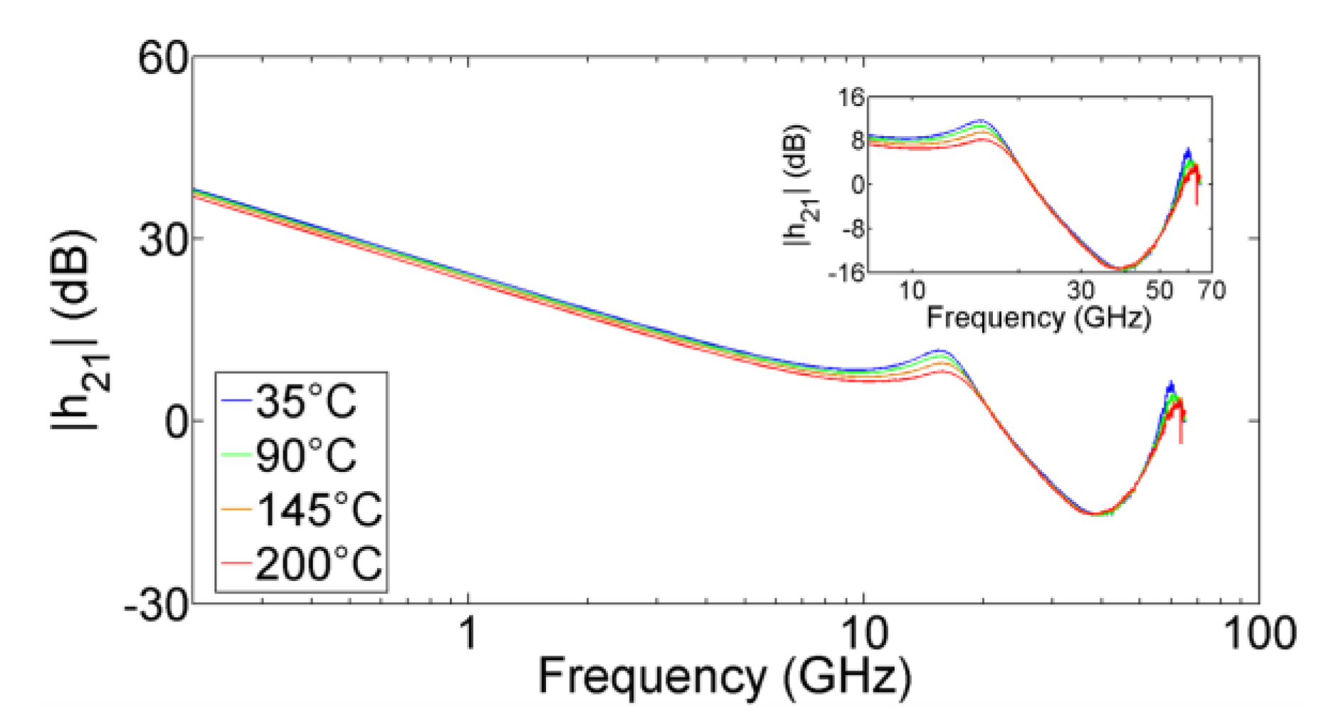
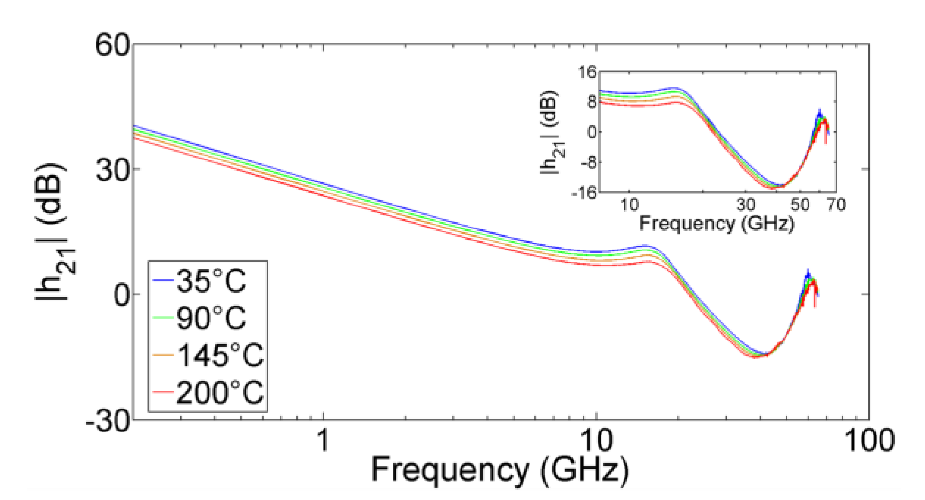
Figure 8 and Figure 9 report the measured h21 at the four investigated ambient temperatures with VDS = 30 V and for two values of VGS: −3.5 V and −3.1 V, respectively. It is found that two peaks appear in h21 at each bias condition. It has already been demonstrated in previous works that the first peak is due to the resonance between the extrinsic inductances and the intrinsic capacitances [7,8,9,12,13], whereas the second peak is due to the resonance of the extrinsic inductive and capacitive contributions [12,13]. The experiments show that the second peak is substantially insensitive to Ta, as expected considering that the extrinsic reactive elements are mostly temperature-independent, and the first peak is roughly independent of Ta, consistently with the slight temperature dependence of the intrinsic capacitances.
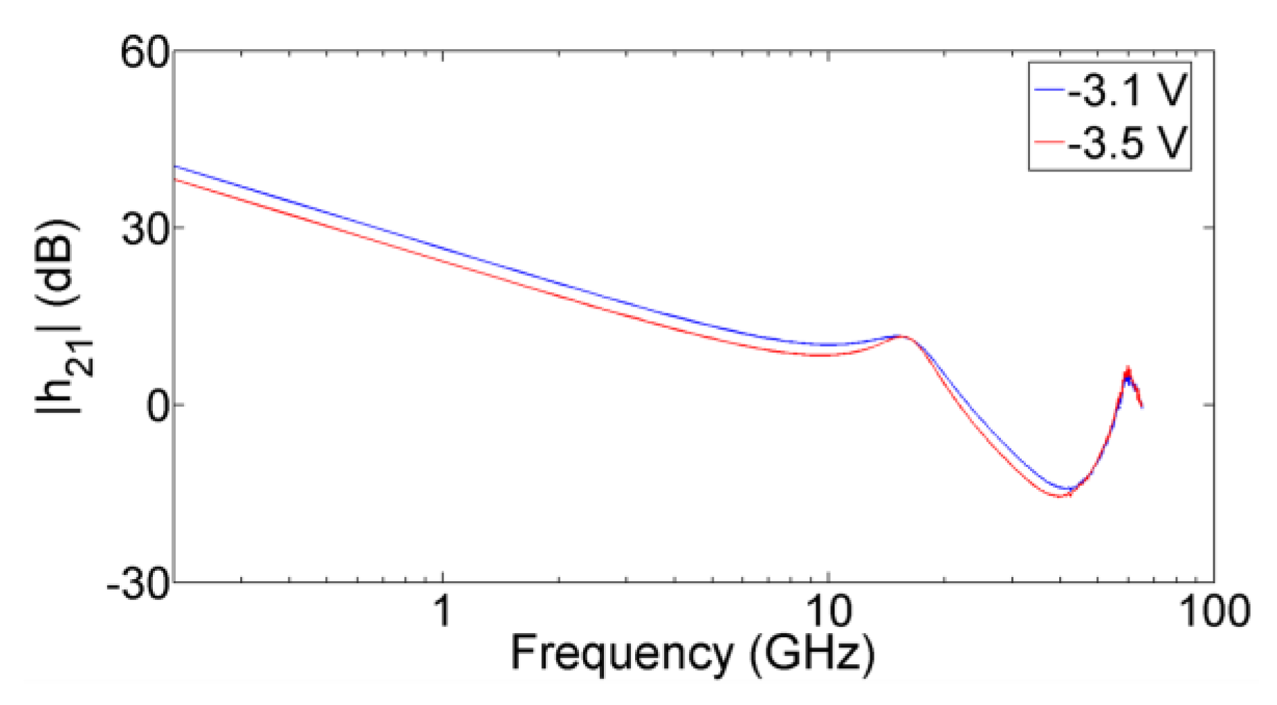
To focus attention on the VGS dependence, Figure 10 illustrates h21 measured at Ta = 35 °C, VDS = 30 V and with VGS equal to −3.5 V and −3.1 V. By varying VGS from −3.5 to −3.1 V, the improvement of gm leads to an increase of the low-frequency magnitude of h21 but the two peaks are mostly insensitive to this variation of VGS.
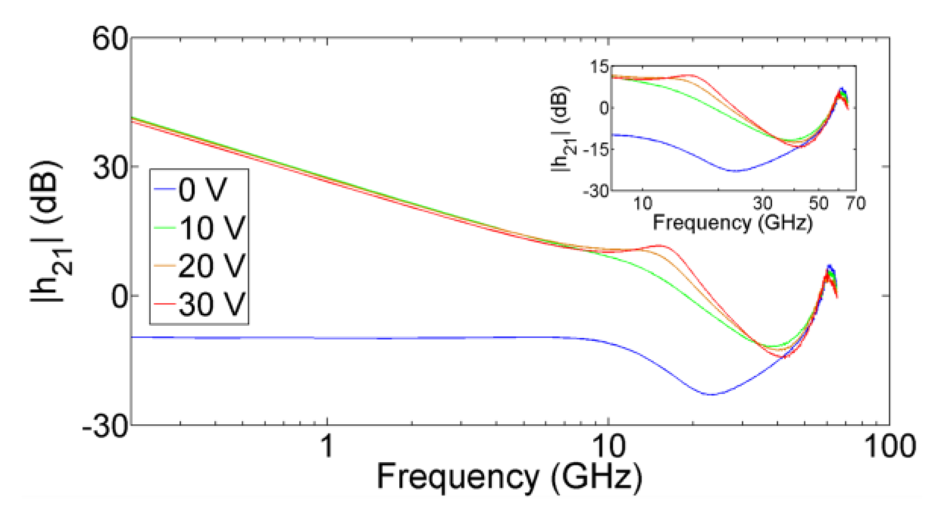
As can be observed in Figure 11, the first peak disappears at zero VDS, owing to the reduction of Rds that tends to short circuit the intrinsic capacitive contributions [7,9,12]. On the other hand, the second peak is mostly insensitive to VDS, owing to the bias independence of the extrinsic reactive elements [12].
Figure 12a reports the comparison between measured and simulated h21 at Ta = 35 °C, VDS = 30 V, and VGS = −3.1 V. As can be observed, the standard equivalent-circuit model is able to predict the two peaks in h21. Figure 12b illustrates that a reduction of gm results in a dramatic degradation of the low-frequency magnitude of h21 but with the two peaks still affecting h21. It is worth noticing that the first kink effect in the simulated h21 vanishes by reducing Rds to zero (see Figure 12c), whereas h21 is substantially insensitive to an increase of Rds (see Figure 12d).

4. Conclusions

We have reported a thorough and critical investigation of the kinks in S22 and h21 parameters for solid-state electronic devices. To gain a comprehensive and in-depth understanding of their origin, we have developed a measurement-based analysis focusing on a GaN HEMT as a case study. However, the achieved outcomes can be straightforwardly generalized to other FET types, since a standard topology of FET equivalent circuit has been successfully used for analyzing and comprehending the experiments. We have shown that the kink in S22 depends on both temperature and bias conditions, the first peak in h21 depends slightly on temperature and strongly on bias conditions, and the second peak in h21 is substantially bias- and temperature-insensitive. We have reported an exhaustive interpretation of the experimental findings by using a standard transistor equivalent-circuit model as it allows capturing all the three observed kinks. The origin of the kink effect in S22 is mostly due to a high value of gm, the first peak in h21 originates from the resonance between the extrinsic inductances and the intrinsic capacitances, and the second kink in h21 originates from the resonance of the extrinsic inductive and capacitive contributions. A reduction of gm allows only suppression of the kink effect in S22, while a reduction of Rds leads to the suppression of the kink effect in S22 and the first peak in h21 by short circuiting the contributions of gm and intrinsic capacitances. On the other hand, it has been shown that the second peak in h21 still occurs, independently of the reduction of gm and Rds.

Author Contributions

Investigation, G.C. and V.V.; Methodology, G.C. and A.R.; Supervision, G.V. and A.C.; Writing–original draft, G.C.; Writing–review & editing, A.R., V.V., G.V. and A.C.

Funding

This research was funded in part by the Eurostars project E!10149 MicromodGaN.

Conflicts of Interest

The authors declare no conflict of interest.

References

  1. Lu, S.-S.; Meng, C.; Chen, T.-W.; Chen, H.-C. The origin of the kink phenomenon of transistor scattering parameter S22. IEEE Trans. Microw. Theory Tech. 2001, 49, 333–340. [Google Scholar] [CrossRef]
  2. Lu, S.-S.; Meng, C.; Chen, T.-W.; Chen, H.-C. A novel interpretation of transistor S-parameters by poles and zeros for RF IC circuit design. IEEE Trans. Microw. Theory Tech. 2001, 49, 406–409. [Google Scholar] [CrossRef]
  3. Lin, Y.-S.; Lu, S.-S. An analysis of the kink phenomenon of scattering parameter S22 in RF power mosfets for system-on-chip (SOC) applications. Microw. Opt. Technol. Lett. 2003, 36, 371–376. [Google Scholar] [CrossRef]
  4. Lin, Y.-S. Temperature dependence of the power gain and scattering parameters S11 and S22 of an RF nMOSFET with advanced RF-CMOS technology. Microw. Opt. Technol. Lett. 2005, 44, 180–185. [Google Scholar] [CrossRef]
  5. Crupi, G.; Avolio, G.; Raffo, A.; Barmuta, P.; Schreurs, D.M.M.-P.; Caddemi, A.; Vannini, G. Investigation on the thermal behavior for microwave GaN HEMTs. Solid-State Electron. 2011, 64, 28–33. [Google Scholar] [CrossRef]
  6. Crupi, G.; Raffo, A.; Caddemi, A.; Vannini, G. The kink phenomenon in the transistor S22: A systematic and numerical approach. IEEE Microw. Wirel. Comp. Lett. 2012, 22, 406–408. [Google Scholar] [CrossRef]
  7. Crupi, G.; Raffo, A.; Schreurs, D.M.M.-P.; Avolio, G.; Caddemi, A.; Vannini, G. A clear-cut understanding of the current-gain peak in HEMTs: Theory and experiments. Microw. Opt. Technol. Lett. 2012, 54, 2801–2806. [Google Scholar] [CrossRef]
  8. Crupi, G.; Raffo, A.; Schreurs, D.M.M.-P.; Avolio, G.; Caddemi, A.; Vannini, G. Identification of the intrinsic capacitive core for GaAs HEMTs by investigating the frequency behavior of the impedance parameters. Microw. Opt. Technol. Lett. 2013, 55, 1237–1240. [Google Scholar] [CrossRef]
  9. Crupi, G.; Raffo, A.; Marinković, Z.; Avolio, G.; Caddemi, A.; Marković, V.; Vannini, G.; Schreurs, D.M.M.-P. An extensive experimental analysis of the kink effects in S22 and h21 for a GaN HEMT. IEEE Trans. Microw. Theory Tech. 2014, 62, 513–520. [Google Scholar] [CrossRef]
  10. Ahsan, S.A.; Ghosh, S.; Khandelwal, S.; Chauhan, Y.S. Modeling of kink-effect in RF behaviour of GaN HEMTs using ASM-HEMT model. In Proceedings of the IEEE International Conference on Electron Devices and Solid-State Circuits, Hong Kong, China, 3–5 August 2016; pp. 426–429. [Google Scholar]
  11. Ahsan, S.A.; Ghosh, S.; Khandelwal, S.; Chauhan, Y.S. Pole-zero approach to analyze and model the kink in gain-frequency plot of GaN HEMTs. IEEE Microw. Wirel. Comp. Lett. 2017, 27, 266–268. [Google Scholar] [CrossRef]
  12. Crupi, G.; Raffo, A.; Vadalà, V.; Avolio, G.; Schreurs, D.M.M.-P.; Vannini, G.; Caddemi, A. Technology-independent analysis of the double current-gain peak in millimeter-wave FETs. IEEE Microw. Wirel. Comp. Lett. 2018, 28, 326–328. [Google Scholar] [CrossRef]
  13. Crupi, G.; Raffo, A.; Vadalà, V.; Vannini, G.; Caddemi, A. Current-gain in FETs beyond cut-off frequency. Microw. Opt. Technol. Lett. 2018, 60, 3019–3023. [Google Scholar] [CrossRef]
  14. Shohat, J.; Robertson, I.D.; Nightingale, S.J. Investigation of drain-line loss and the S22 kink effect in capacitively coupled distributed amplifiers. IEEE Trans. Microw. Theory Tech. 2005, 53, 3767–3773. [Google Scholar] [CrossRef]
  15. Gao, H.; Sun, X.; Hua, Y.; Zhang, X.; Wang, R.; Li, G.P. A composite transistor to suppress kink phenomenon in HBTs for broadband design. IEEE Electron. Device Lett. 2010, 31, 1113–1115. [Google Scholar] [CrossRef]
  16. Grinberg, A.A.; Luryi, S. Coherent transistor. IEEE Trans. Electron. Dev. 1993, 40, 1512–1522. [Google Scholar] [CrossRef]
  17. Luryi, S.; Xu, J.; Zaslavsky, A. Future Trends in Microelectronics Reflections on the Road to Nanotechnology; Kluwer Academic Publishers: Dordrecht, The Netherlands, 1996. [Google Scholar]
  18. Jorke, H.; Schafer, M. Resonance phase operation of bipolar transistors. In Proceedings of the IEEE Topical Meeting on Silicon Monolithic Integrated Circuits in RF Systems, Garmisch, Germany, 11 April 2003; pp. 26–28. [Google Scholar]
  19. Kasper, E.; Eberhardt, J.; Jorke, H.; Luy, J.-F.; Kibbel, H.; Dashiell, M.W.; Schmidt, O.G.; Stoffel, M. SiGe resonance phase transistor: Active transistor operation beyond the transit frequency fT. Solid State Electron. 2004, 48, 837–840. [Google Scholar] [CrossRef]
  20. Heim, S.; Wanner, R.; Stoffel, M.; Kasper, E. Resonance phase operation of a SiGe HBT. Mat. Sci. Semic. Proc. 2005, 8, 319–322. [Google Scholar] [CrossRef]
  21. Cressler, J.D. Silicon Heterostructure Devices; CRC Press, Taylor and Francis Group: Boca Raton, FL, USA, 2008. [Google Scholar]
  22. Trew, R.J. Wide bandgap semiconductor transistors for microwave power amplifiers. IEEE Microw. Mag. 2000, 1, 46–54. [Google Scholar] [CrossRef]
  23. Colantonio, P.; Giannini, F.; Giofrè, R.; Limiti, E.; Serino, A.; Peroni, M. AC-band high-efficiency second-harmonic-tuned hybrid power amplifier in GaN technology. IEEE Trans. Microw. Theory Tech. 2006, 54, 2713–2722. [Google Scholar] [CrossRef]
  24. Marinković, Z.; Crupi, G.; Caddemi, A.; Avolio, G.; Raffo, A.; Marković, V.; Vannini, G.; Schreurs, D.M.M.-P. Neural approach for temperature dependent modeling of GaN HEMTs. Int. J. Numer. Model. 2015, 28, 359–370. [Google Scholar] [CrossRef]
  25. Quaglia, R.; Camarchia, V.; Pirola, M.; Ghione, G. GaN Monolithic power amplifiers for microwave backhaul applications. Electronics 2016, 5, 25. [Google Scholar] [CrossRef]
  26. Alim, M.A.; Rezazadeh, A.A.; Gaquiere, C. Temperature effect on DC and equivalent circuit parameters of 0.15-μm gate length GaN/SiC HEMT for microwave applications. IEEE Trans. Microw. Theory Tech. 2016, 64, 3483–3491. [Google Scholar] [CrossRef]
  27. Jarndal, A.; Kouki, A. Efficient modeling of GaN HEMTs for linear and nonlinear circuits design. Int. J. Numer. Model. 2017, 30, e2100. [Google Scholar] [CrossRef]
  28. Wen, Z.; Xu, Y.; Wang, C.; Zhao, X.; Chen, Z.; Xu, R. A parameter extraction method for GaN HEMT empirical large-signal model including self-heating and trapping effects. Int. J. Numer. Model. 2017, 30, e2137. [Google Scholar] [CrossRef]
  29. Ramella, C.; Piacibello, A.; Quaglia, R.; Camarchia, V.; Pirola, M. High efficiency power amplifiers for modern mobile communications: The load-modulation approach. Electronics 2017, 6, 96. [Google Scholar] [CrossRef]
  30. Foundry Process Data Sheet. Ref.: 170112_DS GaN GH25 Process_7012, United Monolithic Semiconductors, Villebon-sur-Yvette, France. Available online: https://www.ums-gaas.com/wp-content/uploads/2017/05/PPH25X.pdf (accessed on 15 October 2018).
  31. Floriot, D.; Brunel, V.; Camiade, M.; Chang, C.; Lambert, B.; Ouarch-Provost, Z.; Blanck, H.; Grunenputt, J.; Hosch, M.; Jung, H.; Splettstober, J.; Meiners, U. GH25-10: New qualified power GaN HEMT process from technology to product overview. In Proceedings of the 9th European Microwave Integrated Circuits Conference, Rome, Italy, 6–7 October 2014; pp. 225–228. [Google Scholar]
  32. Camarchia, V.; Colantonio, P.; Giannini, F.; Giofrè, R.; Jiang, T.; Pirola, M. A design strategy for AM/PM compensation in GaN Doherty power amplifiers. IEEE Access 2017, 5, 22244–22251. [Google Scholar] [CrossRef]
  33. Gonzalez, G. Microwave Transistor Amplifiers Analysis and Design; Prentice-Hall: Upper Saddle River, NJ, USA, 1996. [Google Scholar]
  34. Crupi, G.; Schreurs, D.M.M.-P.; Caddemi, A. Effects of gate-length scaling on microwave MOSFET performance. Electronics 2017, 6, 62. [Google Scholar] [CrossRef]
  35. Dambrine, G.; Cappy, A.; Heliodore, F.; Playez, E. A new method for determining the FET small-signal equivalent circuit. IEEE Trans. Microw. Theory Tech. 1988, 36, 1151–1159. [Google Scholar] [CrossRef]
  36. Tayrani, R.; Gerber, J.E.; Daniel, T.; Pengelly, R.S.; Rhode, U.L. A new and reliable direct parasitic extraction method for MESFETs and HEMTs. In Proceedings of the 1993 23rd European Microwave Conference, Madrid, Spain, 6–10 September 1993; pp. 451–453. [Google Scholar]
  37. Jarndal, A.; Kompa, G. An accurate small-signal model for AlGaN-GaN HEMT suitable for scalable large-signal model construction. IEEE Microw. Wirel. Comp. Lett. 2006, 16, 333–335. [Google Scholar] [CrossRef]
  38. Crupi, G.; Caddemi, A.; Schreurs, D.M.M.-P.; Dambrine, G. The large world of FET small-signal equivalent circuits. Int. J. RF Microw. Comput.-Aided Eng. 2016, 26, 749–762. [Google Scholar] [CrossRef]
  39. Wen, Z.; Xu, Y.; Wang, C.; Zhao, X.; Xu, R. An efficient parameter extraction method for GaN HEMT small-signal equivalent circuit model. Int. J. Numer. Model. 2017, 30, e2127. [Google Scholar] [CrossRef]
Figure 1. (a) Photograph of the studied GaN HEMT and (b) its small-signal equivalent circuit.
Electronics 07 00353 g001
Figure 2. Measured (a) S11, (b) S12, (c) S21, (d) S22, (e) magnitude of S21, and (f) magnitude of S22 from 0.2 to 65 GHz for a GaN HEMT at VDS = 30 V and VGS = −3.5 V under four ambient temperatures: 35 °C, 90 °C, 145 °C, and 200 °C.
Electronics 07 00353 g002
Figure 3. Measured (a) S11, (b) S12, (c) S21, (d) S22, (e) magnitude of S21, and (f) magnitude of S22 from 0.2 to 65 GHz for a GaN HEMT at VDS = 30 V and VGS = −3.1 V under four ambient temperatures: 35 °C, 90 °C, 145 °C, and 200 °C.
Electronics 07 00353 g003
Figure 4. Measured (a) S11, (b) S12, (c) S21, (d) S22, (e) magnitude of S21, and (f) magnitude of S22 from 0.2 to 65 GHz for a GaN HEMT at Ta = 35 °C and VDS = 30 V for two values of VGS: −3.5 V and −3.1 V.
Electronics 07 00353 g004aElectronics 07 00353 g004b
Figure 5. Measured (a) S11, (b) S12, (c) S21, (d) S22, (e) magnitude of S21, and (f) magnitude of S22 from 0.2 to 65 GHz for a GaN HEMT at Ta = 35 °C and VGS = −3.1 V for four values of VDS: 0 V, 10 V, 20 V, and 30 V. S21 at VDS = 0 V is multiplied by a factor of 30 in Figure 4c for better readability.
Electronics 07 00353 g005
Figure 6. Comparison between measured and simulated (a) S22 and (b) its magnitude from 0.2 to 65 GHz for a GaN HEMT at Ta = 35 °C, VDS = 30 V, and VGS = −3.1 V. The values of gm and Rds for the extracted equivalent-circuit model are 347.9 mS and 138.9 Ω, respectively. The simulated S22 is compared with the simulations achieved by using the models with: (c,d) gm = 0 mS, (e,f) Rds = 0 Ω, and (g,h) Rds = 10 kΩ.
Electronics 07 00353 g006
Figure 7. Measured (a) S11, (b) S12, (c) S21, and (d) S22 from 0.2 to 65 GHz for a GaN HEMT at Ta = 35 °C and VDS = 0 V for two values of VGS: −4 V and 0 V.
Electronics 07 00353 g007
Figure 8. Measured h21 from 0.2 to 65 GHz for a GaN HEMT at VDS = 30 V and VGS = −3.5 V under four ambient temperatures: 35 °C, 90 °C, 145 °C, and 200 °C.
Electronics 07 00353 g008
Figure 9. Measured h21 from 0.2 to 65 GHz for a GaN HEMT at VDS = 30 V and VGS = −3.1 V under four ambient temperatures: 35 °C, 90 °C, 145 °C, and 200 °C.
Electronics 07 00353 g009
Figure 10. Measured h21 from 0.2 to 65 GHz for a GaN HEMT at Ta = 35 °C and VDS = 30 V for two values of VGS: −3.5 V and −3.1 V.
Electronics 07 00353 g010
Figure 11. Measured h21 from 0.2 to 65 GHz for a GaN HEMT at Ta = 35 °C and VGS = −3.1 V for four different values of VDS: 0 V, 10 V, 20 V, and 30 V.
Electronics 07 00353 g011
Figure 12. Comparison between measured and simulated (a) h21 from 0.2 to 65 GHz for a GaN HEMT at Ta = 35 °C, VDS = 30 V, and VGS = −3.1 V. The values of gm and Rds for the extracted equivalent-circuit model are 347.9 mS and 138.9 Ω, respectively. The simulated h21 is compared with the simulations achieved by using the models with: (b) gm = 0 mS, (c) Rds = 0 Ω, and (d) Rds = 10 kΩ.
Electronics 07 00353 g012aElectronics 07 00353 g012b