Abstract
In this paper, we analyze the performance of cooperative power domain non-orthogonal multiple access (NOMA) in power line communication (PLC) networks. Due to the high signal attenuation of the source to user links, a relay aids communication from the source to two users. With half-duplex transmission, the source transmits a superimposed symbol in the first phase. The relay utilizes amplify-and-forward (AF) and decode-and-forward (DF) protocol on the received superimposed signal and forwards it to the users in the second phase. We derive analytic expressions for the outage probability and the system throughput of the proposed system under a PLC log-normal channel with impulsive noise. Based on the results for AF NOMA relaying case, we analyze the system performance at high signal-to-noise ratio (SNR) and derive closed-form lower and upper bounds for the outage probability. Simulation results show an improvement in the outage probability and the system throughput performance of the AF and DF NOMA schemes compared to the NOMA without relaying transmission and conventional orthogonal multiple access scheme. Furthermore, the impact of the channel variance is highlighted in the results. It is shown that the DF NOMA has a better outage probability than the AF NOMA scheme for low channel variance scenarios (i.e., less branches and connected loads in the PLC network). However, as the channel variance increases, AF NOMA scheme has similar outage probability performance as the DF NOMA scheme. In addition, it is shown that the system throughput is enhanced when the relay employs DF relaying compared to AF relaying.
1. Introduction
There is a growing body of research that shows non-orthogonal multiple access (NOMA) as a promising multiple access technique for next generation communication systems. The basic idea of NOMA is to allow multiple users to share the same time/frequency/space resources. Generally, NOMA can be applied in the power domain or code domain. However, power domain NOMA (PD-NOMA) has gained more traction since it is easily applicable to current systems [1,2]. In PD-NOMA, a source transmits a superimposed signal to different users with appropriate power allocation. Each user is able to recover its desired signal by the application of successive interference cancellation (SIC). Compared to orthogonal multiple access (OMA) techniques such as time-division multiple access (TDMA) and frequency-division multiple access (FDMA), NOMA offers higher spectral efficiency and achievable rate [3]. However, users with better channel conditions naturally benefit more with NOMA than users with worse channel conditions due to increased multiple access interference at their receivers [4].
The advent of NOMA has enabled research on many conventional techniques, one of which is cooperative relaying [5,6,7,8,9]. In cooperative communications, the relay usually operates with amplify-and-forward (AF) or decode-and-forward (DF) protocols where the advantage of the AF protocol lies in its low processing cost compared to the DF protocol [9]. However, it is shown that the two protocols generally achieve very similar performance when the relay to user link is unreliable [10]. Cooperative communication as applied to NOMA comes in two forms. First, there is the user relaying with DF protocol where a user (typically with strong channel conditions) acts as a relay to forward information to the user with weak channel conditions [11,12,13]. On the other hand, there also exists dedicated relay transmission between the source and the users [14,15,16,17]. The capacity of user relaying NOMA was analyzed in Reference [11]. To improve on the ergodic sum-rate and outage probability performance in Reference [11], a novel receiver design was introduced in Reference [12], where the destination jointly decodes the received symbols by using maximum ratio combining (MRC) and SIC. The authors of Reference [13] studied user relaying with the capability to switch between half-duplex (HD) and full-duplex (FD) modes to enhance system performance. Under direct and non-direct link scenarios, FD NOMA is shown to be better than HD NOMA in terms of the outage probability and the ergodic sum-rate in the low signal-to-noise ratio (SNR) region. While variable gain AF relaying was studied in Reference [14], the authors of Reference [15] considered a fixed gain AF relay with direct and non-direct links. In References [14,15], the system performance was analyzed under the assumption of Nakagami-m channels. Moreover, a comparison of AF and DF relaying with partial channel state information (CSI) was discussed in Reference [16]. Based on the analysis, it is shown that, although DF relaying has better outage probability than AF relaying, the performance gap between AF and DF relaying for the outage probability is negligible as the SNR increases.
As an enabler of smart grid (SG) and Internet of Things (IoT) applications, power line communication (PLC) is seen as an attractive and promising technique due to the ubiquitous nature of power lines [18]. Naturally, the application of NOMA to PLC can only prove beneficial [19,20,21,22]. In Reference [19], user relaying NOMA with DF protocol was proposed for PLC systems. The average sum capacity was analyzed and results show NOMA can significantly improve the performance of PLC compared to OMA and satisfy the electromagnetic compatibility (EMC) requirements [23]. The authors of [20] studied a two-stage NOMA scheme, where NOMA is applied at both the source and the user relay, which is shown to outperform the one-stage system in Reference [19]. An adaptive cooperative NOMA scheme for PLC was proposed in Reference [21], where a dedicated DF relay establishes communication between a source modem and two user modems. Depending on the feedback information in the second phase, a direct or cooperative transmission increases the system throughput performance compared to TDMA and a conventional cooperative NOMA scheme. A joint power allocation was proposed for a multi-user NOMA visbile light communication (VLC) network in Reference [22]. Here, VLC is enabled by a PLC modem. By jointly optimizing the allocated power to the PLC and VLC links, NOMA performs better than OMA in terms of sum throughput. The aforementioned works [19,20,21] have only considered DF relaying with NOMA in cooperative PLC systems.
In this paper, we propose cooperative NOMA for PLC systems. The relay aids communication between the source and two users (near and far users) due to the high signal attenuation of the direct link. This is in contrast to the system model studied in References [21,24], where a direct link exists between the source and the near user. We study the system model under a log-normal fading assumption with impulsive noise characteristic to PLC networks [25,26,27,28,29]. Data communication is executed in two equal phases. In the first phase of communication, the source modem transmits a superimposed signal with appropriate power allocation to the relay modem. The relay utilizes the AF or DF protocol on the received signal and forwards it to the two users in the second phase. We derive analytic expressions for the outage probability and the system throughput for the AF and DF NOMA protocols. By analyzing the results of the AF NOMA scheme in the high SNR region, we obtain closed-form lower and upper bounds of the outage probability. The derived analytic expressions are shown to be tight in comparison with Monte Carlo simulations. Furthermore, we show that the derived closed-form lower bound is able to approximate the outage probability especially at high SNR. The superiority of the proposed AF and DF NOMA schemes is illustrated by comparing with the conventional OMA scheme and direct NOMA transmission without relaying. From the simulation results, it is revealed that the DF NOMA outperforms AF NOMA in terms of outage probability in low channel variance settings. However, as the channel variance increases, DF NOMA has similar performance with the AF NOMA scheme. Furthermore, it is shown that the system throughput is enhanced when the relay employs DF relaying compared to AF relaying.
The rest of the paper is organized as follows: Section 2 describes the system model for the AF and DF NOMA schemes in PLC networks. Analysis of the outage probability and the system throughput is presented in Section 3. In Section 4, we describe two benchmark schemes for comparison. The simulation results and subsequent discussions are presented in Section 5. Finally, Section 6 concludes the paper.
Notation: , and denote the probability density function (PDF), cumulative distribution function (CDF) and the complementary CDF (CCDF) of the random variable (RV) X, respectively. , , , and denote the Gaussian Q function, the probability, the expectation, the minimum and the maximum operators, respectively.
2. System Model
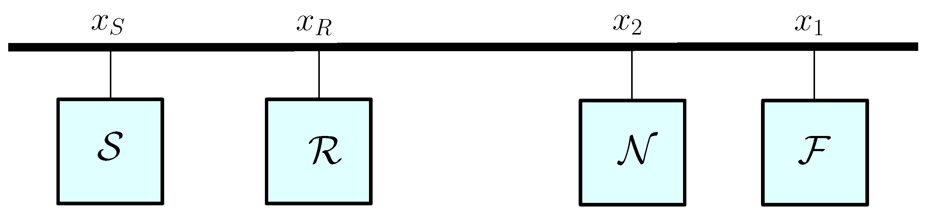
Consider the cooperative PLC network shown in Figure 1, where a source modem communicates with two users and through a relay with AF or DF protocol. It is assumed that the direct link between the source and the users is highly attenuated compared to the source to relay and the relay to user links. The two users, and , are designated as the near user and the far user, respectively. In addition, the CSI is assumed to be perfectly known at all receiving modems. The distance-dependent cable attenuation is modeled as where is the distance between the PLC modems, f represents the operating frequency in , k is the exponent of the attenuation factor, and are the attenuation constants acquired from measurement data [30].
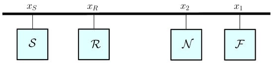
Figure 1.
System model of cooperative relaying in power line communication (PLC) networks.
The source-to-relay, relay-to-near user and relay-to-far user channels are denoted by , and , respectively. We assume all channels experience independent and identically distributed log-normal fading which is common in the PLC literature [25,26,27]. The PDF of the PLC log-normal fading channel is given by
where is a scaling constant and and (in decibels) are the mean and variance of , respectively, which follows the Gaussian distribution. In PLC networks, the channel variance accounts for the branch network topology where its value increases as the number of branches and connected loads in the network increases [19]. In essence, low channel variance relates to a good fading scenario while high channel variance relates to a bad fading scenario [31].
The performance of any PLC network is limited by the several sources of noise that can be broadly categorized as colored background noise, narrowband interference and impulsive noise [32]. To accurately capture the noise effects, several models have been proposed including the Bernoulli-Gaussian process, Middleton Class A, Markov-Middleton and Markov-Gaussian models [28,29]. In this work, we adopt the Bernoulli-Gaussian model due to its mathematical tractability [28]. Using the Bernoulli-Gaussian model, the PLC noise is modeled as an aggregate of background noise and impulsive noise [26]. The impulsive noise is assumed to occur with a probability of p while the background noise occurs with a probability of in a transmission block.
The proposed relaying strategy with NOMA for the cooperative PLC network occurs in two phases. Let and denote the messages to be transmitted with . During the first phase, the source modem sends the superimposed signal expressed as to the relay modem . Here, is the source transmit power, and are the power allocation coefficients for and , respectively. Due to the weak channel conditions of the far user , its designated symbol , is allocated more power. Therefore, the following conditions hold: and . The received signal at is expressed as
where represents the noise at with variance .
In the second phase, the relay forwards a new data signal to the two users after applying the AF or DF protocol. While the AF protocol amplifies the received signal, the DF protocol rebuilds the superimposed signal of and upon successful decoding of the received signal [16]. With a relay transmit power , the transmitted signal , is expressed as
where is the variable relay gain given by [33]
Therefore, the received signals at the near user and the far user are expressed, respectively, as
and
where and represent the noise at the near user and the far user with variance and , respectively.
2.1. Amplify-and-Forward Relaying
Based on the fact that is allocated more power, the far user decodes its desired signal by treating as interference. As a result, the post-detection instantaneous signal-to-interference-plus-noise ratio (SINR) for at the far user is written as
In order to retrieve its desired signal , the near user decodes and removes it through SIC. Consequently, the post-detection SINRs at the near user for and are, respectively, given by
and
2.2. Decode-and-Forward Relaying
The DF relay decodes the superimposed signal in the first phased based on the NOMA principle that is, is decoded first since it is allocated more power. After this, is obtained by SIC where is reencoded and subtracted from the composite signal. The instantaneous SINRs for detecting and are, respectively, written as
and
The far and near users can recover their desired signals after relay transmission in the second phase. Since more power is allocated to the far user, it decodes its intended data symbol directly by treating as interference. The instantaneous SINR at the far user, , for decoding is obtained as
To decode its desired data symbol , the near user first decodes and applies SIC. The SINR of detecting is expressed as
Finally, the instantaneous SNR at the near user for detecting is given by
In the next section, we derive analytic expressions for the outage probability and the system throughput for the proposed AF and DF NOMA schemes under PLC log-normal channels with impulsive noise.
3. Outage Probability Analysis
Without loss of generality, we define , and . and denote the source and relay transmit SNR. In this work, we assume erasure decoding, where the received signals affected by impulsive noise are discarded in the decoding process [19,20,21]. An outage occurs when the achievable rate is less than the predefined target rate. Let and denote the rate thresholds for and , where the outage SNRs for and are and , respectively.
3.1. Amplify-and-Forward NOMA
First, we analyze the outage probability of the far user , which is defined as
By defining , , and , we have
where and are the PDF and CCDF of the RVs X and Y, respectively, where since must be satisfied. Noting that the RVs X and Y are log-normally distributed with parameters and , respectively, we have
and
denotes the Gaussian Q function defined as
Due to SIC decoding, the outage probability of the near user is expressed as [33]
By defining , , and , we have
where
The outage probability of the near user is evaluated as
where and are the PDF and CCDF of the RVs X and Z, respectively. Noting that the RVs X and Z are log-normally distributed with parameters and , respectively, we have
where must be satisfied.
3.2. Asymptotic Outage Probability of AF NOMA
In this section, we analyze the user outage probabilities of the AF NOMA at high SNR. This allows us to derive closed-form lower and upper bounds of the exact outage probabilities of the far user and the near user obtained in (20) and (25), respectively. Through simulation results, it will be shown that the lower bounds are tight particularly at high SNR. First, we assume equal source and relay transmit SNR such that . Using (7), (8) and (9), the outage probabilities of the far user and the near user are, respectively, re-expressed as [14]
and
where
and
In the high SNR region (i.e., ) and from (26), the outage probability of the far user is given by
where is obtained by substituting and . is a log-normal RV distributed as . According to Reference [14], the following inequality holds
where u and v are RVs. Based on (31), the lower bound (LB) and upper bound (UB) for the outage probability of the far user are, respectively, found as
and
The CDFs and are, respectively, given by
and
where for , respectively. By following a similar procedure as above, the LB and UB for the outage probability of the near user are, respectively, represented as
and
The CDFs and are, respectively, expressed by
and
where for , respectively. is a log-normal RV distributed as and .
3.3. Decode-and-Forward NOMA
Based on (10) and (12), the outage probability of the far user, , is expressed as
is evaluated as
where must be satisfied. Similarly, using (12), is calculated as
By substituting (41) and (42) into (40), the outage probability of the far user with DF NOMA is given by
Here, is calculated as
where
Following , is derived as
where
3.4. System Throughput
Subsequently, we analyze the system throughput performance. When the system transmits at a fixed data rate, the throughput is an important metric to characterize system performance. The throughput is the product of the fixed transmission rate and the successful communication probability [13]. The system throughput, , of the proposed NOMA PLC network is deduced as
where . and are the throughputs of the far user and the near user, respectively. For AF NOMA, and are obtained from (20) and (25), respectively. For DF NOMA, and are obtained from (43) and (49), respectively.
Optimum power allocation is essential to maximizing the system throughput of the proposed cooperative NOMA schemes. However, due to the complicated form of the outage probability expressions, it is very difficult to obtain closed-from expressions for the power allocation parameters. In this case, maximum system throughput is derived by performing an exhaustive search over the range of power allocation coefficients. To maximize the system throughput, the power allocation problem is formulated as [34]
4. Benchmark Schemes
To highlight the performance of the AF and DF NOMA schemes under various settings, this section presents two different benchmark schemes namely NOMA without relaying and OMA schemes, respectively.
4.1. NOMA without Relaying (D-NOMA)
The NOMA without relaying scheme is used as a benchmark for comparison. In the D-NOMA transmission, the source transmits the data signals and with appropriate power allocation directly to the designated users without the help of the relay. In line with the NOMA protocol with SIC, the users can recover their desired signals.
4.2. OMA Transmission
As a benchmark scheme for comparison, the source sends information to the two users via the relay using a OMA scheme [35]. The information transfer is completed in four orthogonal phases. The source transmit their data signals and to the relay in the first and second phases, respectively. In the third and fourth phases, the relay forwards the data signals and to the far user and the near user, respectively. Each data signal is transmitted at full power.
5. Simulation Results
In this section, we present extensive simulation results to evaluate the performance of the proposed cooperative NOMA schemes in PLC networks. Our results are validated through Monte Carlo simulations averaged over channel realizations. To characterize the power line attenuation, we adopt the following parameters: and [9]. The power allocation coefficients of the NOMA transmission are fixed such that and [19,20,21]. For simplicity, we consider equal channel mean and variances such that and [36]. The probability of impulsive noise occurrence is set as and the target rates are given by and , respectively. Unless otherwise stated, , and , respectively.
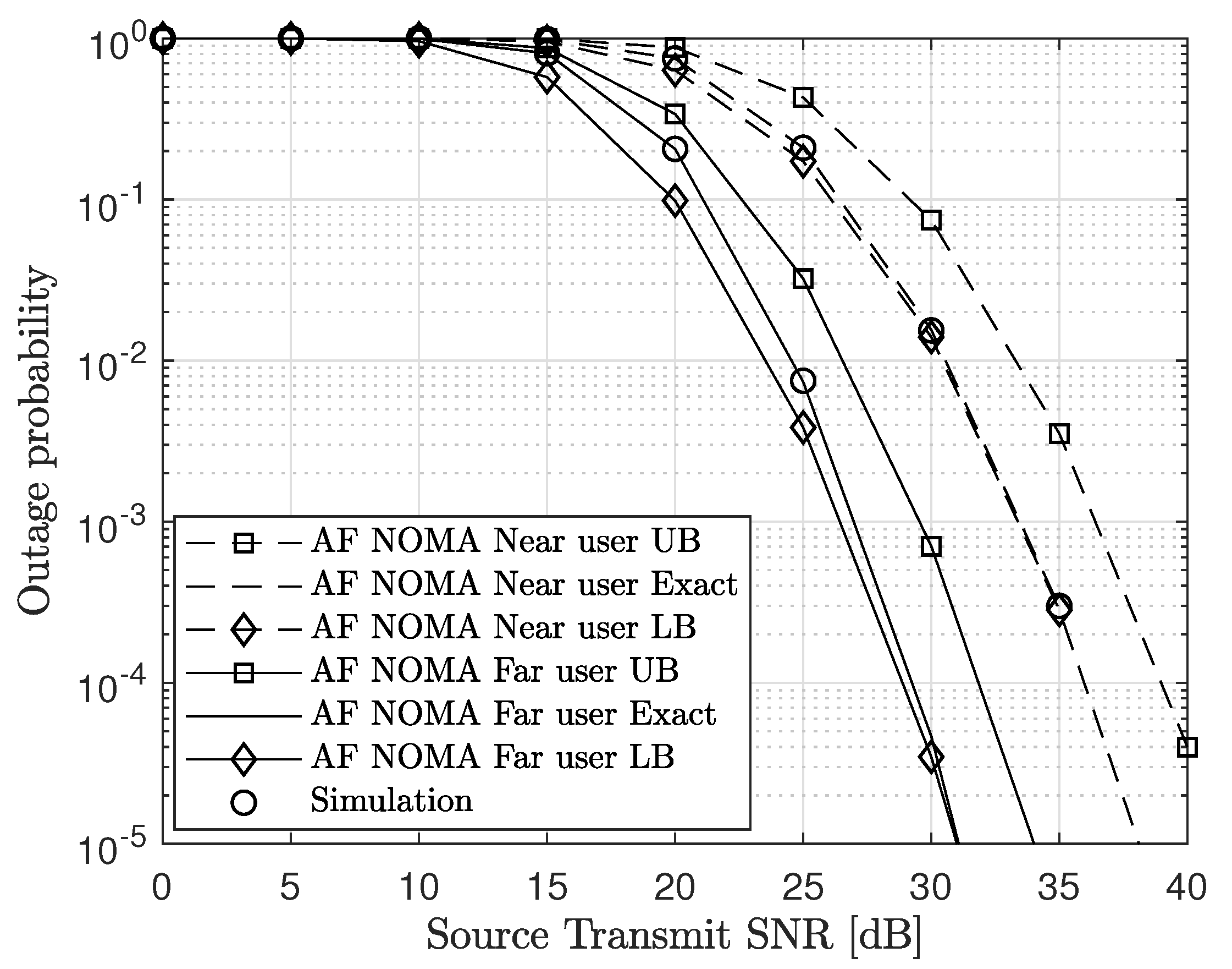
In Figure 2, we plot the outage probability of the AF NOMA scheme versus the source transmit SNR. We illustrate the performance for a fixed power allocation and equal source and relay transmit powers that is, . From the plot, we can observe that the analytic results show a tight approximation to the simulation results verifying the accuracy of the derived analytic results in (20) and (25). Also, the derived closed-form LBs of the outage probability for the far and near users obtained from (32) and (36), respectively are very tight especially at high SNR. Therefore, they can be used to approximate the system performance.
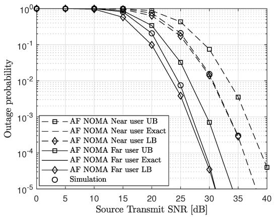
Figure 2.
Outage probability versus source transmit SNR for , , , and .
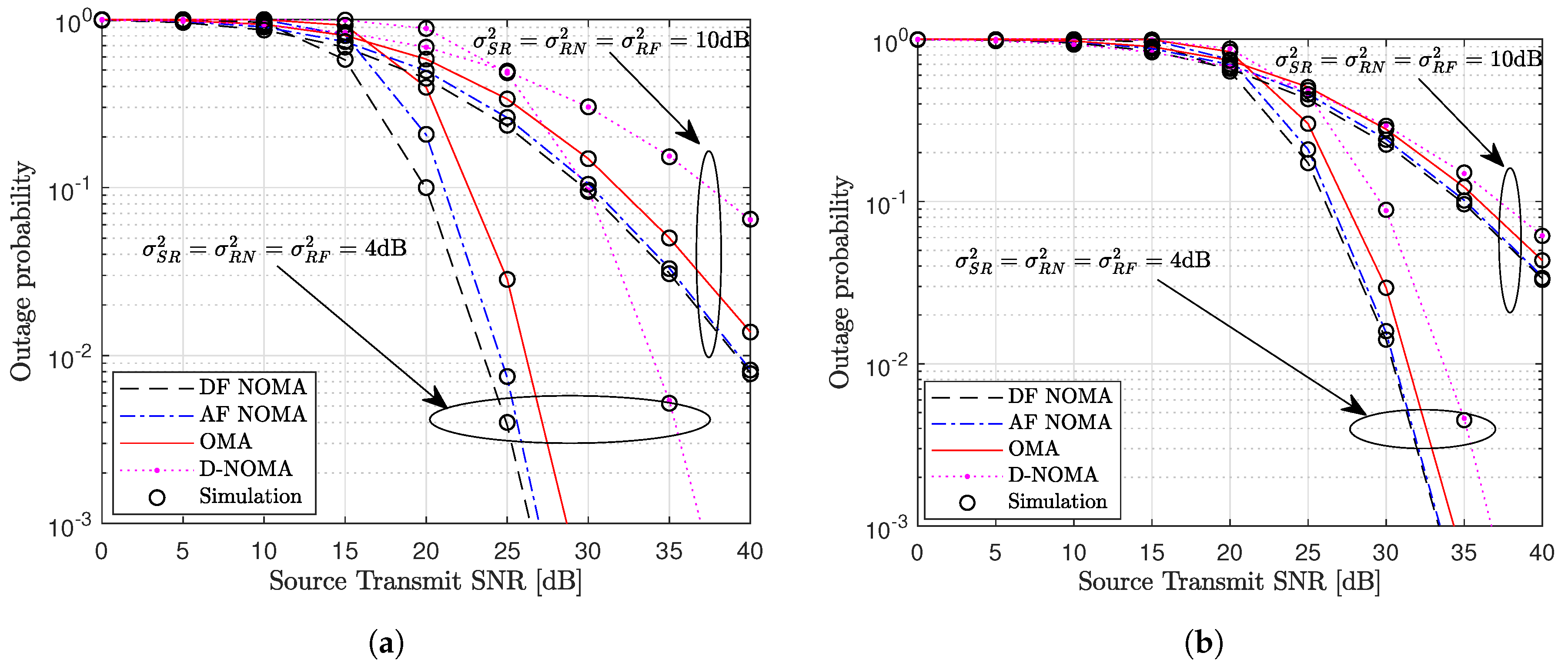
Figure 3 shows the outage probability performance versus the source transmit SNR for the different schemes. We compare the DF and AF NOMA schemes to the benchmark schemes presented in Section 4. From the plot, we can observe that the analytic results show a tight approximation to the simulation results verifying the accuracy of the derived analytic results. For the near and far users, the outage probability of the proposed AF and DF NOMA schemes are enhanced compared to the OMA and NOMA without relaying schemes as shown in Figure 3a,b, respectively. By allocating more power to the far user, the AF and DF NOMA schemes are able to ensure user fairness. Therefore, multiple users can be served concurrently while achieving set quality of service (QoS) requirements. From Figure 3a, it is seen that the DF NOMA scheme has better outage probability than the AF NOMA when the channel variance is low (i.e., ). However, as the channel variance increases from to , the outage probability is similar for the AF and DF NOMA schemes across the whole SNR range. In essence, while DF NOMA scheme can be chosen as the preferred protocol when the channel conditions are good, the AF NOMA scheme can be selected as more loads are connected to network due to its low computational complexity. For the near user, the performance of the AF and DF NOMA schemes remains similar in low and high channel variance settings. As the NOMA without relaying scheme suffers from high signal attenuation, it has the worst outage probability performance.
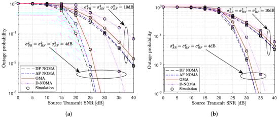
Figure 3.
Outage probability performance of different schemes for (a) far user and (b) near user where , , , and .
Figure 4 shows the system throughput versus the source transmit SNR. The system throughput is plotted using (50). It is observed that the proposed DF and AF NOMA schemes significantly enhance the system throughput relative to the benchmark schemes. The system throughput is enhanced when the relay employs DF instead of AF protocol. This follows directly from the outage probability performance of the two schemes. The AF and DF NOMA schemes will require less power to achieve a set target rate compared to the OMA scheme. For example, for a target rate of and , the DF and AF NOMA schemes will require and , respectively while the OMA scheme will require . Finally, we observe that when the impulsive noise probability increases from to , the outage probability performance is degraded across all schemes. This is because higher p means more received samples are corrupted by impulsive noise and discarded in the decoding process.
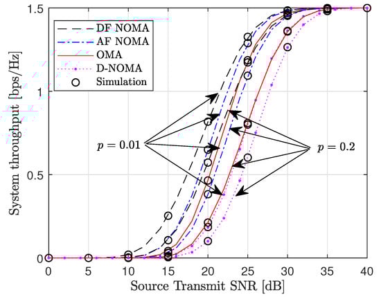
Figure 4.
System throughput versus the source transmit SNR for , , and
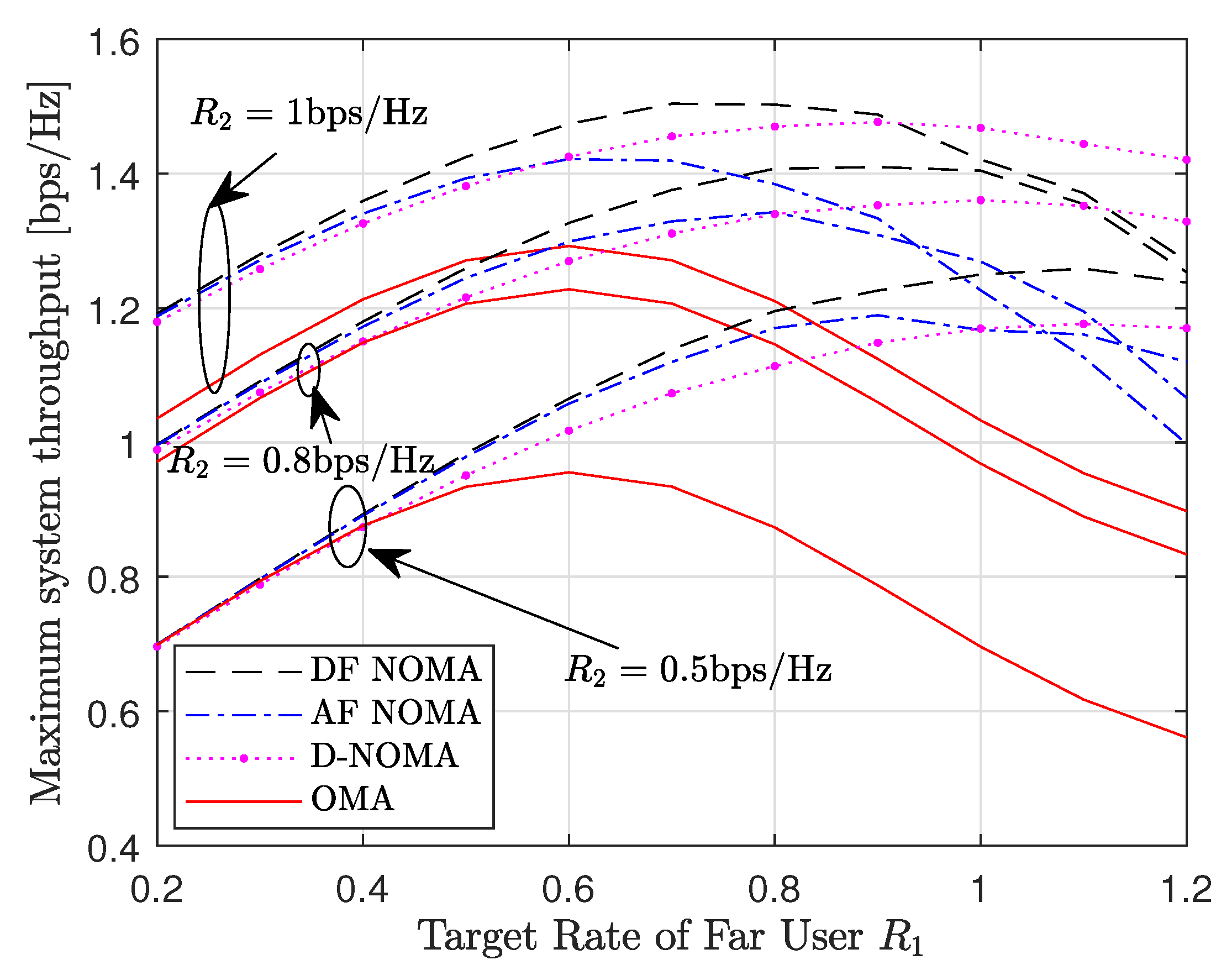
Figure 5 depicts the maximum system throughput versus the far user target rate, . The maximum system throughput is obtained from (51). Specifically, we set the following parameters: , and . From the results, it is shown that the DF NOMA scheme has the best performance while the OMA scheme has the worst performance. The gap between the NOMA schemes and the OMA scheme increases as increases. However, the system throughput of the DF and AF NOMA schemes is dependent on the given target rates of the users. At , as the target rate of the far user increases from to , the throughput of the DF NOMA scheme is enhanced compared to the NOMA without relaying scheme. Beyond , the DF NOMA scheme fails to guarantee the system QoS, hence the system throughput is degraded. A similar observation is made for the AF NOMA scheme where the NOMA without relaying scheme begins to outperform the AF NOMA scheme when . Therefore target rates need to be carefully selected for the AF and DF NOMA schemes to outperform the benchmark schemes.
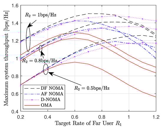
Figure 5.
Maximum system throughput versus the far user target rate for , and .
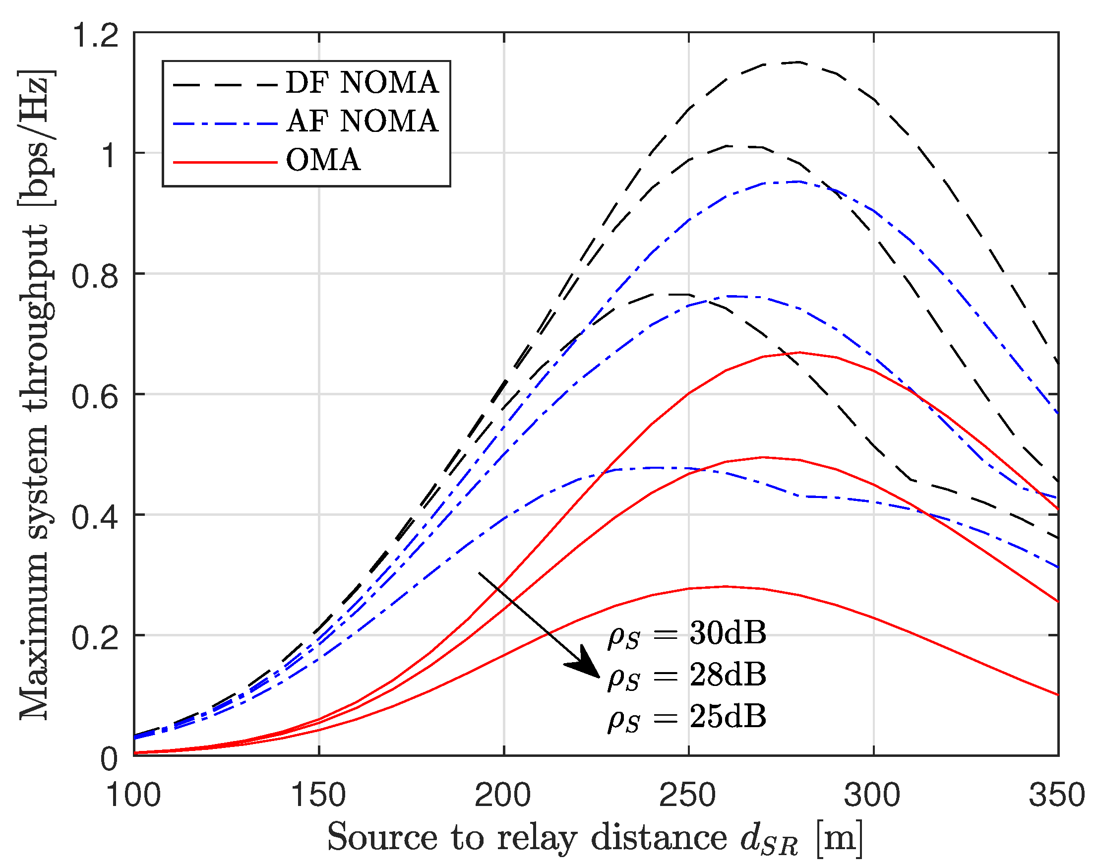
Finally, Figure 6 examines the impact of the relay position on the performance of the proposed NOMA schemes. Specifically, we plot the maximum system throughput versus the source-to-relay distance . The maximum system throughput is plotted using (51). We assume the source-to-far user distance is m and the near user is located m from the far user. From the results, there exists an optimum relay position that maximizes the system throughput. Although the received signal power is high when the relay is close to the source, the far distance between the relay and the users means the forwarded signal in the second phase is highly attenuated, degrading the system throughput. For a fixed relay power, the system throughput is enhanced when the source transmits with more power. In addition, we observe that the DF NOMA scheme is able to enhance the system throughput compared to the other schemes for all relay positions.
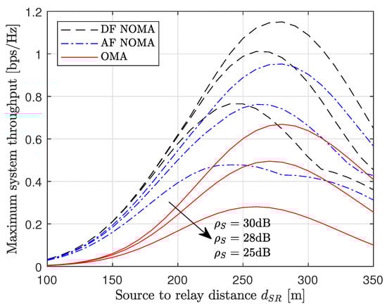
Figure 6.
Maximum system throughput versus source-to-relay distance for for , and and .
6. Conclusions
In this paper, we have proposed cooperative NOMA for PLC networks where the relay aids information transfer between the source and the users. The source uses superposition coding for data transmission to the relay. The relay uses AF or DF protocol and forwards the received signal to the users. We derived analytic expressions for the outage probability and the throughput under PLC log-normal channels with impulsive noise. For AF NOMA scheme, we analyzed the results at high SNR and derived closed-form lower and upper bounds for the outage probability. Through Monte Carlo simulations, we have verified the accuracy of the analysis. The simulation results revealed the superiority of the cooperative NOMA schemes compared to the benchmark schemes in all performance metrics. Comparing AF and DF NOMA, it was shown that DF NOMA has better outage probability than AF NOMA especially when the channel variance is low. Furthermore, the DF NOMA scheme achieves a higher system throughput compared to the AF NOMA scheme. Due to synchronization and channel estimation issues, imperfect SIC can be considered as an extension to this work.
Author Contributions
Conceptualization, Methodology, and Original Draft Preparation R.K.A.; Writing—review and editing, Validation P.A.; Supervision, K.-J.L.
Funding
This research was supported by the research fund of Hanbat National University in 2019.
Conflicts of Interest
The authors declare no conflict of interest.
References
- Ding, Z.; Lei, X.; Karagiannidis, G.K.; Schober, R.; Yuan, J.; Bhargava, V.K. A Survey on Non-Orthogonal Multiple Access for 5G Networks: Research Challenges and Future Trends. IEEE J. Sel. Areas Commun. 2017, 35, 2181–2195. [Google Scholar] [CrossRef]
- Choi, J. On Generalized Downlink Beamforming with NOMA. J. Commun. Netw. 2017, 19, 319–328. [Google Scholar] [CrossRef]
- Zeng, M.; Yadav, A.; Dobre, O.A.; Tsiropoulos, G.I.; Poor, H.V. Capacity Comparison between MIMO-NOMA and MIMO-OMA with Multiple Users in a Cluster. IEEE J. Sel. Areas Commun. 2017, 35, 2413–2424. [Google Scholar] [CrossRef]
- Higuchi, K.; Benjebbour, A. Non-orthogonal Multiple Access (NOMA) with Successive Interference Cancellation for Future Radio Access. IEICE Trans. Commun. 2015, 98-B, 403–414. [Google Scholar] [CrossRef]
- Lee, K.-J.; Kim, J.-S.; Caire, G.; Lee, I. Asymptotic Ergodic Capacity Analysis for MIMO Amplify-and-Forward Relay Networks. IEEE Trans. Wireless Commun. 2010, 9, 2712–2717. [Google Scholar] [CrossRef]
- Song, C.; Lee, K.-J.; Lee, I. MMSE-Based MIMO Cooperative Relaying Systems: Closed-Form Designs and Outage Behavior. IEEE J. Sel. Areas Commun. 2012, 30, 1390–1401. [Google Scholar] [CrossRef]
- Park, J.; Chae, C.-B.; Yoon, G. Amplify-and-Forward Two-Way Relaying System over Free-Space Optics Channels. J. Commun. Netw. 2017, 19, 481–492. [Google Scholar] [CrossRef]
- Asiedu, D.K.P.; Mahama, S.; Jeon, S.-W.; Lee, K.-J. Optimal Power Splitting for Simultaneous Wireless Information and Power Transfer in Amplify-and-Forward Multiple-Relay Systems. IEEE Access 2018, 6, 3459–3468. [Google Scholar] [CrossRef]
- Ahiadormey, R.K.; Anokye, P.; Jo, H.-S.; Lee, K.-J. Performance Analysis of Two-Way Relaying in Cooperative Power Line Communications. IEEE Access 2019, 7, 97264–97280. [Google Scholar] [CrossRef]
- Yu, M.; Li, J. Is Amplify-and-Forward Practically Better Than Decode-and-Forward or Vice Versa? In Proceedings of the IEEE International Conference on Acoustics, Speech, and Signal Processing (ICASSP), Philadelphia, PA, USA, 23 March 2005; Volume 3, pp. 365–368. [Google Scholar] [CrossRef]
- Kim, J.-B.; Lee, I.-H. Capacity Analysis of Cooperative Relaying Systems Using Non-Orthogonal Multiple Access. IEEE Commun. Lett. 2015, 19, 1949–1952. [Google Scholar] [CrossRef]
- Xu, M.; Ji, F.; Wen, M.; Duan, W. Novel Receiver Design for the Cooperative Relaying System With Non-Orthogonal Multiple Access. IEEE Commun. Lett. 2016, 20, 1679–1682. [Google Scholar] [CrossRef]
- Yue, X.; Liu, Y.; Kang, S.; Nallanathan, A.; Ding, Z. Exploiting Full/Half-Duplex User Relaying in NOMA Systems. IEEE Trans. Commun. 2018, 66, 560–575. [Google Scholar] [CrossRef]
- Men, J.; Ge, J.; Zhang, C. Performance Analysis of Nonorthogonal Multiple Access for Relaying Networks Over Nakagami-m Fading Channels. IEEE Trans. Veh. Technol. 2017, 66, 1200–1208. [Google Scholar] [CrossRef]
- Yue, X.; Liu, Y.; Kang, S.; Nallanathan, A. Performance Analysis of NOMA with Fixed Gain Relaying over Nakagami-m Fading Channels. IEEE Access 2017, 5, 5445–5454. [Google Scholar] [CrossRef]
- Wan, D.; Wen, M.; Ji, F.; Liu, Y.; Huang, Y. Cooperative NOMA Systems with Partial Channel State Information Over Nakagami- m Fading Channels. IEEE Trans. Commun. 2018, 66, 947–958. [Google Scholar] [CrossRef]
- Kader, M.F.; Shahab, M.B.; Shin, S.Y. Exploiting Non-Orthogonal Multiple Access in Cooperative Relay Sharing. IEEE Commun. Lett. 2017, 21, 1159–1162. [Google Scholar] [CrossRef]
- Nikfar, B.; Han Vinck, A.J. Relay Selection in Cooperative Power Line Communication: A Multi-Armed Bandit Approach. J. Commun. Netw. 2017, 19, 1–9. [Google Scholar] [CrossRef]
- Rabie, K.M.; Adebisi, B.; Yousif, E.H.G.; Gacanin, H.; Tonello, A.M. A Comparison between Orthogonal and Non-Orthogonal Multiple Access in Cooperative Relaying Power Line Communication Systems. IEEE Access 2017, 5, 10118–10129. [Google Scholar] [CrossRef]
- Rabie, K.M.; Adebisi, B.; Tonello, A.M.; Yarkan, S.; Ijaz, M. Two-Stage Non-Orthogonal Multiple Access over Power Line Communication Channels. IEEE Access 2018, 6, 17368–17376. [Google Scholar] [CrossRef]
- Pu, H.; Liu, X.; Zhang, S.; Xu, D. Adaptive Cooperative Non-Orthogonal Multiple Access-Based Power Line Communication. IEEE Access 2019, 7, 73856–73869. [Google Scholar] [CrossRef]
- Feng, S.; Bai, T.; Hanzo, L. Joint Power Allocation for the Multi-User NOMA-Downlink in a Power-Line-Fed VLC Network. IEEE Trans. Veh. Technol. 2019, 68, 5185–5190. [Google Scholar] [CrossRef]
- Girotto, M.; Tonello, A.M. EMC Regulations and Spectral Constraints for Multicarrier Modulation in PLC. IEEE Access 2017, 5, 4954–4966. [Google Scholar] [CrossRef]
- Yu, Z.; Zhai, C.; Liu, J.; Xu, H. Cooperative Relaying Based Non-Orthogonal Multiple Access (NOMA) With Relay Selection. IEEE Trans. Veh. Technol. 2018, 67, 11606–11618. [Google Scholar] [CrossRef]
- Versolatto, F.; Tonello, A.M. Analysis of the PLC Channel Statistics using a Bottom-Up Random Simulator. In Proceedings of the IEEE International Symposium on Power Line Communications and Its Applications (ISPLC), Rio de Janeiro, Brazil, 28–31 March 2010; pp. 236–241. [Google Scholar] [CrossRef]
- Rabie, K.M.; Adebisi, B.; Gacanin, H.; Nauryzbayev, G.; Ikpehai, A. Performance Evaluation of Multi-Hop Relaying over Non-Gaussian PLC channels. J. Commun. Netw. 2017, 19, 531–538. [Google Scholar] [CrossRef]
- Qian, Y.; Yan, J.; Guan, H.; Li, J.; Zhou, X.; Guo, S.; Jayakody, D.N.K. Design of Hybrid Wireless and Power Line Sensor Networks with Dual-Interface Relay in IoT. IEEE Internet Things J. 2019, 6, 239–249. [Google Scholar] [CrossRef]
- Shongwey, T.; Han Vinck, A.J.; Ferreira, H.C. On Impulse Noise and Its Models. In Proceedings of the IEEE International Symposium on Power Line Communications and Its Applications (ISPLC), Glasgow, UK, 30 March–2 April 2014; pp. 12–17. [Google Scholar] [CrossRef]
- Han, B.; Stoica, V.; Kaiser, C.; Otterbach, N.; Dostert, K. Noise Characterization and Emulation for Low-Voltage Power Line Channels across Narrowband and Broadband. Digit. Signal Process. 2017, 69, 259–274. [Google Scholar] [CrossRef]
- Zimmermann, M.; Dostert, K. A Multipath Model for the Powerline Channel. IEEE Trans. Commun. 2002, 50, 553–559. [Google Scholar] [CrossRef]
- Qian, Y.; Tian, M.; Jiang, X.; Song, H.; Shu, F.; Li, J. Performance analysis for a two-way relaying power line network with analog network coding. Front. Inf. Technol. Electron. Eng. 2015, 16, 892–898. [Google Scholar] [CrossRef]
- Meng, H.; Guan, Y.L.; Chen, S. Modeling and Analysis of Noise Effects on Broadband Power-line Communications. IEEE Trans. Power Deliv. 2005, 20, 630–637. [Google Scholar] [CrossRef]
- Do, D.T.; Nguyen, T.T.T. Impacts of Imperfect SIC and Imperfect Hardware in Performance Analysis on AF Non-Orthogonal Multiple Access Network. Telecommun. Syst. 2019. [Google Scholar] [CrossRef]
- Rabie, K.M.; Adebisi, B. Enhanced Amplify-and-Forward Relaying in Non-Gaussian PLC Networks. IEEE Access 2017, 5, 4087–4094. [Google Scholar] [CrossRef]
- Wang, Z.; Peng, Z. Secrecy Performance Analysis of Relay Selection in Cooperative NOMA Systems. IEEE Access 2019, 7, 86274–86287. [Google Scholar] [CrossRef]
- Atallah, M.; Kaddoum, G. Design and Performance Analysis of Secure Multicasting Cooperative Protocol for Wireless Sensor Network Applications. IEEE Wirel. Commun. Lett. 2019. [Google Scholar] [CrossRef]

© 2019 by the authors. Licensee MDPI, Basel, Switzerland. This article is an open access article distributed under the terms and conditions of the Creative Commons Attribution (CC BY) license (http://creativecommons.org/licenses/by/4.0/).