Abstract
In heterogeneous cellular networks (HetNets), densification of small base stations (SBSs) in the macro base station (MBS) coverage region leads to improved network coverage and capacity. However, this improvement is at the cost of inter-cell interference (ICI) due to the high MBS transmit power. The situation deteriorates further when uniformly deployed wideband jammers (WBJs) to initiate distributed denial-of-service (DDoS) attacks are present. With sufficient knowledge about the network parameters, WBJs produce substantial jammer interference (JI) by transmitting unwanted energy in the legitimate band. Such jamming attacks can cause significant JI in the UL communications of MBS edge users (M-EUs) due to i) low uplink (UL) transmit power of user equipment (UE) and ii) longer distances of M-EUs. As a result of ICI and JI, M-EUs are severely affected and go off the coverage due to a low received signal-to-interference ratio (SIR). Hence, to mitigate both ICI and JI, we use a proactive resource allocation scheme known as reverse frequency allocation (RFA). The results indicate that although ICI and JI significantly degrade network performance, RFA employment leads to improved SIR due to effective ICI and JI mitigation.
1. Introduction
1.1. Motivation
In heterogeneous cellular networks (HetNets), small base stations (SBSs) are overlaid in the coverage region of a macro base station (MBS) to improve network coverage and capacity [1,2,3]. The use of orthogonal frequency division multiple access (OFDMA) in HetNets causes no or limited intra-cell interference, whereas inter-cell interference (ICI) remains one of the main performance-limiting factors [4,5]. Wideband jammers (WBJs) are increasingly being developed to initiate distributed denial of service (DDoS) attacks on targets such as organizations, shopping malls, or public gatherings by transmitting unwanted energy in the legitimate band [6,7,8,9]. With the assumption of having sufficient knowledge about network parameters, such as frequency band, transmit power, and target locations, WBJs create coverage holes caused by jammer interference (JI) [10,11]. Moreover, the notion of uniform jammer distribution is considered to be more effective when there is a large number of jammers in the target proximity [12]. Hence, the uniform WBJs’ distribution leads to substantial JI and, thus, renders a target out of coverage [13,14]. Moreover, uplink (UL) communications of MBS edge users (M-EUs) are susceptible to DDoS attacks [6] due to (i) low UL transmit power of user equipment (UE), and (ii) longer distances of M-EUs from the base station [7,8]. In this paper, we assume that the network is flooded by low-power and low-cost WBJs to target UL communications of the M-EUs [9]. Moreover, WBJs can lead to substantial JI and, thus, push M-EUs off the coverage map [13,14].
Mitigation of both ICI and JI is a challenging task. Different resource management approaches have been proposed to mitigate downlink (DL) and UL interference, such as cell range expansion (CRE) [15], fractional frequency reuse (FFR) [16,17], soft frequency reuse (SFR) [18], and reverse frequency allocation (RFA) [19,20]. It has been investigated that, as compared with other schemes such as CRE, FFR, and SFR, RFA is spectrally more efficient due to its efficient resource utilization [19]. In RFA, UL and DL sub-carriers are used by MBSs and SBSs in reverse fashion while assuming a multi-region environment [19]. In this paper, we employ RFA to counter both JI and ICI in order to improve UL coverage.
1.2. Related Work
In [14], the authors discuss different jamming types, which include barrage jamming, partial-band jamming, automatic gain control jamming, equalization jamming, and synchronization jamming. Moreover, they present different intentional JI with their respective targets, and conclude that a more complex jamming is likely to become a bigger threat due to increase in the sophistication of wireless systems. In [21], the authors investigate the jammer detection along with its types using different neural network approaches in an OFDMA-based signaling scenario. They show that their proposed approach can detect and classify the jamming attacks with 85% accuracy. In [22], the authors consider multiple-input and multiple-output (MIMO) networks affected by advanced jamming attacks, where a jammer has the potential to alter its available energy to jam the target. Hence, advanced jamming is more stealthy and effective. Moreover, they investigate various jamming techniques with their effectiveness in MIMO networks. In [23], the authors design anti-jamming receivers to improve the performance of a massive MIMO uplink system against the jamming. The jammers are assumed to degrade both the pilot and data transmission phases of the system. Moreover, in the pilot phase, the base station estimates both legitimate and jamming channels by exploiting a purposely unused pilot sequence. Their proposed method leads to improved performance under strong jamming attack scenarios due to effective estimation of the jamming channel. In [24], the authors introduce the hybrid automatic repeat request (HARQ) in Layer 2 and a single-input multiple-output (SIMO) anti-jamming technique in Layer 1 in video communication networks. They propose a cross-layer resource allocation method by considering the angle between the jammer and the sender channel vector. The authors demonstrate that by employing their proposed setup, peak signal-to-noise ratio (PSNR) increases by 11.3 dB. In [25], the authors investigate smart jammer attacks on the LTE Physical Uplink Shared Channel (PUSCH), Physical Uplink Control Channel (PUCCH), and the radio access procedure. Moreover, they derive possible mitigation and recommendations to improve the robustness of mission-critical communications.
In [26], the authors perform coverage analysis of non-uniform SBS deployment while assuming SFR and load balancing. Their results demonstrate improved coverage for M-EUs. Similarly, in [27], an RFA scheme along with non-uniform SBS deployment is considered, where SBSs near the MBS are muted, but remain active in the cell edge region. Expressions for both rate coverages and coverage probabilities are derived. The results show that non-uniform SBS deployment in the MBS coverage region achieves significant improvement in rate coverage. In [28], the authors perform coverage analysis of a uniform HetNet by employing RFA and load balancing. Their results indicate that RFA with load balancing effectively mitigates ICI and, hence, improves network performance.
1.3. Approach and Contributions
In this paper, a two-tier HetNet model comprised of SBSs and MBSs is considered. In addition to ICI, WBJs’ attacks are assumed to target the UL communication of M-EUs and, hence, degrade network performance. WBJs lead to JI with their unwanted energy transmission. The proposed setup is shown in Figure 1. MBSs, SBSs, users, and WBJs are deployed using independent homogeneous Poisson point processes (IHPPPs). For RFA employment, the available MBS coverage region, , is divided into two non-overlapping regions, i.e., center region, , and outer region, , with radii and , respectively [29,30] (see Figure 1).
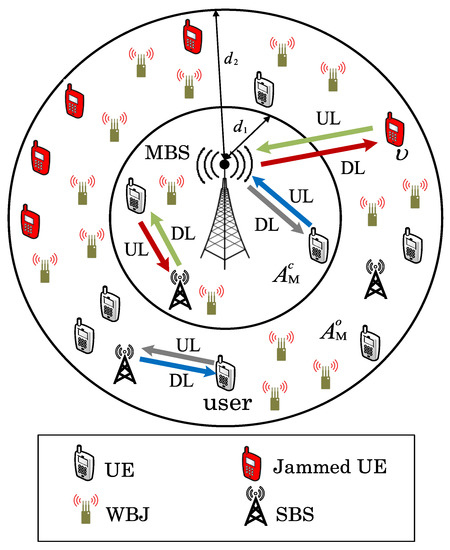
Figure 1.
A two-tier HetNet with wideband jammers (WBJs) and reverse frequency allocation (RFA). The macro base station (MBS), small base stations (SBSs), users, and WBJs follow independent homogeneous Poisson point processes (IHPPPs).
The prime contributions of this paper are given as follows:
- In [14,21,22,23,24,25], different jamming techniques with their detection and mitigation methods are investigated in different networks. However, these studies lack the analysis of both ICI and JI in HetNets along with RFA. Similarly, in [26,27,28], DL coverage analysis was assumed in the respective models. Furthermore, [26,27,28] consider SFR, RFA, ICI, and load balancing in DL HetNets, but lack the analysis of JI in UL HetNets. However, in this paper, we use a unified HetNet model where UL communications are affected by ICI and JI.
- WBJs are assumed to be deployed around the targets to cause severe JI. More specifically, WBJs aim to degrade bottleneck M-EUs’ UL communications, which are prone to intentional and unintentional interferences.
- We analyze UL coverage performance of typical users () (according to the Slivnyak theorem [31], a typical user at origin simplifies and retains the statistical properties of an IHPPP) located in while assuming both ICI and JI.
- Coverage probability expressions are derived for the following network scenarios, given that is located in ; (i) UL coverage probability with WBJs and without RFA employment and (ii) UL coverage probability with WBJs and RFA employment. Here, c and o denote the MBS center and outer region, respectively.
- The results investigate various parameters, such as power transmitted by WBJs, (), SIR threshold, (), jammer density, (), UL transmitted power by , (), and SBS density ().
1.4. Organization of the Paper and Notations
The rest of the paper is organized as follows. In Section 2, we present the system model. In Section 3, coverage probabilities of the proposed model are derived. Numerical results with discussion are presented in Section 4. In Section 5, we conclude the paper. Notations used in the paper are listed in Table 1.

Table 1.
Notation summary.
2. System Model
This section focuses on the proposed network layout, which considers ICI due to multi-tier deployment and JI due to the WBJs’ attacks. In HetNets, UL communication of M-EUs is prone to JI and ICI due to low UL transmit power and longer distances from the MBS. WBJs attack the HetNet with unwanted energy to affect the M-EUs’ coverage performance. Furthermore, mathematical preliminaries are developed in this section, which will be used for the evaluation of coverage performance in Section 3.
2.1. Network Layout with Assumptions
This paper considers a two-tier HetNet, comprised of MBSs, SBSs, users, and WBJs with densities , , , and , respectively. The paper assumes that WBJs try to stress UL communication of M-EUs by transmitting unwanted energy in the legitimate communication band (see Section 2.2 for details on WBJs). The transmit power of WBJs is assumed to be the same as that of users’ UL transmit power. In this paper, to counter both JI and ICI, we use RFA as an effective resource allocation scheme (see Section 2.3 for RFA). The analysis is performed for a typical user. The path loss exponents for MBS and SBSs are denoted as and , respectively. denotes the Rayleigh fading gain, i.e., . User-BS association follows the maximum received power (MRP) strategy [32]. This paper assumes fixed UL transmit power for UE (UL power control or fractional power control can be adopted at the cost of increased complexity and ICI [33,34].).
2.2. WBJs’ Mechanism
WBJs transmit unwanted energy across the entire portion of the spectrum occupied by the target [14] and attack the legitimate communication (in both military and civil applications) to reduce network coverage. We consider WBJs as low-cost transmitters that are deployed randomly in the MBS coverage region through IHPPP. In such a scenario, UL communication of M-EUs is affected the most due to the severe ICI and longer distance of M-EUs from the MBS. WBJs can be tuned as desired to jam any communication frequency. Due to their wideband nature, their power can be as small as that of the UL transmit power of UE, and barely causes any damage when there are few WBJs. However, as the density and power of the WBJs increase, it leads to considerable JI and, thus, degrades network performance. More specifically, in HetNets, UL communication of M-EUs can be completely blocked by increasing WBJs’ density and transmit power.
2.3. Reverse Frequency Allocation
RFA based resource partitioning not only enhances the coverage but also reduces interference, as there is no dedicated spectrum distribution allocated for SBS transmission. Thus, by employing RFA, the whole MBS spectrum is made available to SBSs, but in the reverse direction and in non-overlapping regions. In RFA, different sub-bands between SBSs and MBSs are used in in a complementary fashion, as shown in Figure 2. Here, M and S indicate the MBS and SBS, respectively.
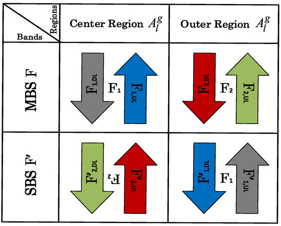
Figure 2.
The RFA model in a two-tier HetNet.
According to RFA, the total allocated frequency, F, is divided into two sub-bands, i.e., and , such that F = , as shown in Figure 2. Here, and denote the sub-bands of MBS to be used in and , respectively. Sub-bands and are further divided into UL and DL sub-carriers and are modeled as and , respectively. The sub-bands, and , of the MBS are used as the frequency sub-bands, and , for the SBSs but in reverse directions with corresponding alternate regions, i.e., the SBS outer region, , and the SBS center region, , respectively. The bands for SBSs, and , are further divided into UL and sub-carriers and are given as and , respectively.
3. Coverage Probability Analysis
In this section, expressions for coverage probabilities are derived for the following network scenarios, given that is located in and in : (i) UL coverage probability with WBJs and without RFA employment (see Section 3.1), and (ii) UL coverage probability with WBJs and RFA employment (see Section 3.2).
3.1. UL Coverage Probability with WBJs and Without RFA Employment
In the HetNet under consideration, the WBJs are assumed to be deployed uniformly throughout the MBS coverage region using IHPPP to degrade UL communication of the M-EUs. Moreover, JI and ICI are the major performance limiting factors in such a network scenario. The UL coverage probability expression, , for MBS associated in with uniformly deployed WBJs and without RFA employment, can be written as
Here, denotes the UL SIR threshold, provided that is associated with MBS, while represents the UL received SIR by MBS from . from Equation (1) can be written as
In Equation (2), the UL interference in is the sum of interferences from (i) MBS-tier, i.e., , (ii) SBS-tier, i.e., , and (iii) WBJs, i.e., . denotes the distance of M-EU from the BS or WBJs. Moreover, is the UL transmit power of . are the power transmitted by MBSs, SBSs, and WBJs, respectively. , , and are the IHPPPs of MBSs, SBSs, and WBJs, respectively. Moreover, denote the elements of sets , , and , respectively. Furthermore, A denotes the MBS coverage area, i.e., .
Here, denote the Laplace transforms of , , and , respectively. Moreover, denotes the expectation of the Laplace transforms.
The Laplace transform of interference received from MBS-tier in A, , is obtained as
In Equation (4), Step (a) is obtained by substituting the value of s, Step (c) is obtained by computing the Laplace transform of Step (b) with respect to , Step (d) is obtained by using the probability generating function (PGFL) of IHPPP [32], Step (e) is obtained by substituting into Step (d), and Step (f) is obtained by Gauss-hypergeometric approximation of Step (e) [35]. Moreover, is the ratio of to , where is the transmit power of MBS.
Using the same approach as that of Equation (4), the Laplace transform of the interference received from SBS-tier, , in A, can be written as
Here, is the ratio of and , where is the transmit power of the SBS.
Similarly, by using the same approach as that of Equation (4), the Laplace transform of the interference received from WBJs, , in A, can be given as
Here, is the ratio of and , where is the transmit power of the WBJs, and and define the effective attacking areas of the jammers, s.t., .
Given that is located in or in (denoted as and , respectively) while associated with the MBS at a distance , the PDFs of its distance from MBS are given, respectively, as [36,37]
and
The UL coverage probability expression, , for MBS-associated in , while considering uniform distribution of WBJs and without RFA employment, can be written as
By substituting Equations (4)–(7) into Equation (9), is given as Equation (11). In Equation (11), indicates the Gauss-hypergeometric function.
Similarly, the UL coverage probability expression, , for MBS-associated in , while considering uniform WBJs’ distribution and without RFA employment, can be written as
3.2. UL Coverage Probability with WBJs and RFA Employment
The UL coverage probability, , in the presence of WBJs and RFA employment while considering in can be written as
Due to RFA employment, the UL interference is the sum of the UL interference from MBS-tier in , i.e., , the DL interference from SBS-tier in , i.e., , and the interference from WBJs, i.e., . Therefore, from Equation (13) can be written as
Equation (14) can be expanded as
Here, is the UL transmit power of which is associated with the MBS, is the DL transmit power of the SBS, and is the transmit power of the WBJs. Moreover, substituting Equation (14) into Equation (13), we obtain as
The Laplace transform of the UL interference from MBS-tier in , i.e., , is obtained as
Moreover, the Laplace transform of the DL interference from SBS-tier in , i.e., , can be written in a similar way to that of Equation (17), and is given as
Here, because in is approximately equal to in . is the ratio of and , where is the DL transmit power of the SBSs.
From Equation (17), the Laplace transform of the DL interference from MBS-tier in , i.e., , is obtained as
The UL coverage probability expression, , for MBS-associated in , while considering uniformly deployed WBJs and RFA employment, can be written as
By substituting Equations (6), (7), (17), and (18) into Equation (20), is expressed as Equation (22).
Similarly, the UL coverage probability expression, , for MBS-associated in , while considering uniformly deployed WBJs and RFA employment, can be given as
4. Results and Discussion
In this section, we describe UL coverage probability results for while considering (i) UL coverage probability with WBJs and without RFA employment, and (ii) UL coverage probability with WBJs and RFA employment. The results were drawn using MATLAB 2017a. MBSs, SBSs, users, and WBJs are considered to be distributed in , s.t., . Moreover, transmit powers of MBS, SBS, , and WBJs are assumed to be 60 dBm, 40 dBm, 20 dBm, and 20 dBm, respectively. The simulation parameters are listed in Table 2. Moreover, the effects of different network parameters, such as , , , , , and , are considered for UL coverage, given that is located in .
Table 2.
Simulation parameters.
Figure 3 compares UL coverage probabilities in versus different values of . The figure signifies the fact that higher values of lead to significant JI and, thus, lower coverage. Moreover, the figure depicts that RFA employment causes improved coverage both in the presence and absence of WBJs. This is due to the fact that with RFA, the number of interfering SBSs is reduced.
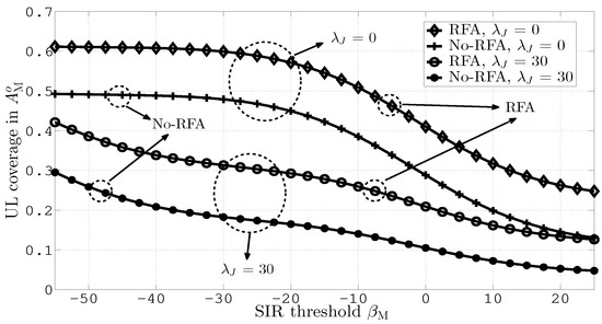
Figure 3.
Uplink (UL) coverage in versus different values of .
Figure 4 measures UL coverage probabilities in versus different values of the SIR threshold, and . This figure is generated for = 0, 20, 40, 60, 80, 100. In the figure, an additional comparison of RFA with SFR is also performed, where 5% UL coverage improvement is obtained by RFA due to effective interference management. It can be observed from the figure that the coverage improves with RFA. This is because of efficient resource utilization and effective interference mitigation by RFA. Moreover, increasing causes severe UL coverage degradation due to significant JI.
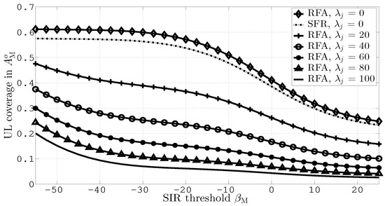
Figure 4.
UL coverage in versus different values of and .
Figure 5 shows the numerical and simulation results for UL coverage probabilities in versus different values of the SIR threshold, and . The results consider both RFAs while assuming . The plots in this figure indicate that RFA outperforms other scenarios by effectively mitigating ICI and JI.
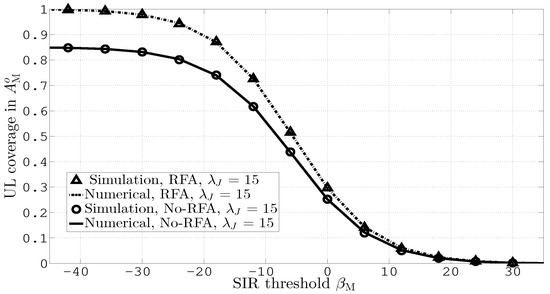
Figure 5.
UL coverage in versus different values of and .
Figure 6 compares the proposed model with [19] while considering ICI and No-RFA. Both the plots consider the same set of parameters as those indicated in Table 2 of [19]. Both the plots in Figure 6 are comparable. However, minor deviations in the plots are due to the noise consideration by [19].
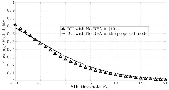
Figure 6.
Coverage probability versus different values of .
Figure 7a,b presents UL coverage probabilities in versus different values of with and without RFA employment, respectively. The figures were generated while assuming = −40, −30, −20, −10, and 0 dB. The figures demonstrate that the increasing value of leads to lower coverage due to higher JI. Moreover, the figures also show that RFA leads to improved coverage due to better ICI and JI mitigation. Furthermore, the results reveal that higher values of lead to improved coverage due to higher UE association with BS.
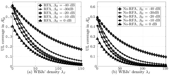
Figure 7.
UL coverage in versus different values of , (a) with RFA and (b) without RFA employment.
Figure 8a,b compares UL coverage probabilities in versus different values of with and without RFA employment, respectively. The figures assume = dB and = 0, 20, 40, 60, and 80. Here, = dB leads to meaningful and improved coverage analysis. Other values of may also be selected; however, higher values of lead to lower coverage and vice versa [38,39]. The results indicate that an increase in the value of leads to lower UL coverage due to higher JI. Moreover, RFA employment enhances the UL coverage, as depicted Figure 8a, compared with the No-RFA scenario, as indicated in Figure 8b. This is due to the smaller number of SBSs as interferences.
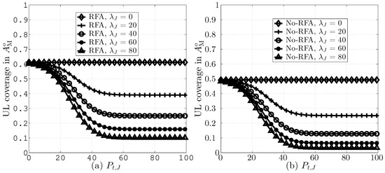
Figure 8.
UL coverage in versus different values of , (a) with RFA and (b) without RFA employment.
In Figure 9a,b, we present UL coverage probabilities in versus different values of WBJs’ distribution area radii while assuming = dB and = 20, 40, 60, 80, and 100. The results indicate that an increase in the WBJs’ distribution area leads to improved UL coverage due to the lower number of WBJs per unit area, and hence, makes the WBJs less effective. Moreover, RFA employment improves the UL coverage due to efficient resource allocation.
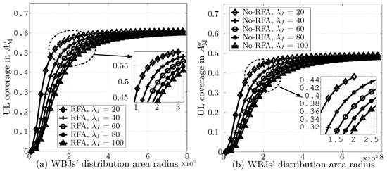
Figure 9.
UL coverage in versus different values of radius for WBJs’ distribution area, (a) with RFA and (b) without RFA employment.
Similarly, Figure 10a,b computes UL coverage probabilities in versus different values of WBJs’ distribution area radii while assuming = 60 and = −60, −40, −20, 0, and 20 dB. The results indicate that an increase in the WBJs’ distribution area leads to improved UL coverage due to lower JI. Moreover, the results also demonstrate that higher values of reduce the UL coverage due to the lower number of user associations.
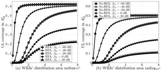
Figure 10.
UL coverage in versus different values of radii for WBJs’ distribution area and , (a) with RFA and (b) without RFA employment.
5. Conclusions
We have investigated UL coverage in the presence of ICI and JI interference in multi-tier HetNets. The paper assumes that MBSs, SBSs, users, and WBJs are uniformly deployed using IHPPPs. The results were generated by evaluating different network parameters such as the WBJs’ transmit power, WBJs’ density, SIR threshold, and WBJs’ distribution area with and without RFA employment. The results indicate that RFA leads to higher UL coverage as compared with the No-RFA scenario, due to better ICI and JI mitigation. Moreover, RFA employment leads to 5% UL coverage as compared with SFR, due to better interference mitigation. Furthermore, the results show that the WBJs’ density greater than 80/, WBJs’ distribution area less than , and WBJs’ transmit power greater than 50 dB lead to UL coverage probability of less than 10%, which is below the acceptable levels. As a future work, smart WBJs can be considered with variable transmit powers to minimize coverage probability.
Author Contributions
Conceptualization: M.S.H. and F.M.; methodology, M.S.H.; software: M.S.H., F.M. and Z.H.A.; validation: F.M., G.A. and Z.H.A; formal analysis, M.S.H. and F.M.; investigation: M.S.H., F.M., G.A. and Z.H.A.; data curation: M.S.H. and Z.H.A.; writing—original draft preparation, M.S.H., F.M., G.A. and Z.H.A.; supervision: F.M., G.A. and Z.H.A.; project administration: M.S.H. and S.K.; funding acquisition: S.K.
Funding
This work (S2666095) was supported by project for Cooperative R&D between Industry, Academy, and Research Institute funded Korea Ministry of SMEs and Startups in 20.
Conflicts of Interest
The authors declare no conflict of interest.
References
- Hassan, N.; Fernando, X. Massive MIMO wireless networks: An overview. Electronics 2017, 6, 63. [Google Scholar] [CrossRef]
- Abbas, Z.H.; Muhammad, F.; Jiao, L. Analysis of load balancing and interference management in heterogeneous cellular networks. IEEE Access 2017, 5, 14690–14705. [Google Scholar] [CrossRef]
- Le, C.B.; Do, D.T.; Voznak, M. Wireless-powered cooperative MIMO NOMA networks: Design and performance improvement for cell-edge users. Electronics 2019, 8, 328. [Google Scholar] [CrossRef]
- Xu, W.; Zhang, H. Uplink interference mitigation for heterogeneous networks with user-specific resource allocation and power control. EURASIP J. Wirel. Commun. Netw. 2014, 2014, 55. [Google Scholar] [CrossRef]
- Hefnawi, M. Hybrid Beamforming for Millimeter-Wave Heterogeneous Networks. Electronics 2019, 8, 133. [Google Scholar] [CrossRef]
- Mirkovic, J.; Reiher, P. A taxonomy of DDoS attack and DDoS defense mechanisms. ACM SIGCOMM Comput. Commun. Rev. 2004, 34, 39–53. [Google Scholar] [CrossRef]
- Jover, R.P. Security attacks against the availability of LTE mobility networks: Overview and research directions. In Proceedings of the IEEE 16th International Symposium on Wireless Personal Multimedia Communications (WPMC), Atlantic, NJ, USA, 24–27 June 2013; pp. 1–9. [Google Scholar]
- Huo, Y.; Fan, X.; Ma, L.; Cheng, X.; Tian, Z.; Chen, D. Secure communications in tiered 5G wireless networks with cooperative jamming. IEEE Trans. Wirel. Commun. 2019. [Google Scholar] [CrossRef]
- Jundong, W. Complex environment noise barrage jamming effects on airborne warning radar. Am. J. Remote Sens. 2018, 6, 59–63. [Google Scholar]
- Ham, C.V.; Scoughton, T.E. Radio Frequency Jammer. U.S. Patent 7,318,368, 15 January 2008. [Google Scholar]
- Viterbi, A. A robust ratio-threshold technique to mitigate tone and partial band jamming in coded MFSK systems. In Proceedings of the IEEE MILCOM 1982-IEEE Military Communications Conference-Progress in Spread Spectrum Communications, Boston, MA, USA, 17–20 October 1982; Volume 1, pp. 22–24. [Google Scholar]
- Grover, K.; Lim, A.; Yang, Q. Jamming and anti-jamming techniques in wireless networks: A survey. Int. J. Ad Hoc Ubiquitous Comput. 2014, 17, 197–215. [Google Scholar] [CrossRef]
- Wang, S.; Gao, Y.; Sha, N.; Zhang, G.; Zang, G. Physical layer security in K-tier heterogeneous cellular networks over Nakagami-m channel during uplink and downlink phases. IEEE Access 2019, 7, 14581–14592. [Google Scholar] [CrossRef]
- Lichtman, M.; Poston, J.D.; Amuru, S.; Shahriar, C.; Clancy, T.C.; Buehrer, R.M.; Reed, J.H. A communications jamming taxonomy. IEEE Secur. Privacy 2016, 14, 47–54. [Google Scholar] [CrossRef]
- Naganuma, N.; Nakazawa, S.; Suyama, S.; Okumura, Y.; Otsuka, H. Performance evaluation of adaptive control CRE in HetNet with eICIC scheme. IEICE Commun. Express 2017, 6, 166–171. [Google Scholar] [CrossRef]
- Fereydooni, M.; Sabaei, M.; Dehghan, M.; Eslamlou, G.B.; Rupp, M. Analytical evaluation of heterogeneous cellular networks under flexible user association and frequency reuse. Comput. Commun. 2018, 116, 147–158. [Google Scholar] [CrossRef]
- Akhtar, M.S.; Abbas, Z.H.; Muhammad, F.; Abbas, G. Analysis of decoupled association in HetNets using soft frequency reuse scheme. AEU Int. J. Electron. Commun. 2019, 152961. [Google Scholar] [CrossRef]
- Guo, L.; Cong, S.; Sun, Z. Multichannel analysis of soft frequency reuse and user association in two-tier heterogeneous cellular networks. EURASIP J. Wirel. Commun. Netw. 2017, 2017, 168. [Google Scholar] [CrossRef]
- Muhammad, F.; Abbas, Z.H.; Abbas, G.; Jiao, L. Decoupled downlink-uplink coverage analysis with interference management for enriched heterogeneous cellular networks. IEEE Access 2016, 4, 6250–6260. [Google Scholar] [CrossRef]
- Sial, M.N.; Ahmed, J. A realistic uplink–downlink coupled and decoupled user association technique for K-tier 5G HetNets. Arabian J. Sci. Eng. 2019, 44, 2185–2204. [Google Scholar] [CrossRef]
- Gecgel, S.; Goztepe, C.; Kurt, G.K. Jammer detection based on artificial neural networks: A measurement study. In Proceedings of the ACM Workshop on Wireless Security and Machine Learning, Miami, FL, USA, 15–17 May 2019; pp. 43–48. [Google Scholar]
- Zhang, L.; Restuccia, F.; Melodia, T.; Pudleswki, S.M. Jam sessions: Analysis and experimental evaluation of advanced jamming attacks in MIMO networks. arXiv 2019, arXiv:1904.07613. [Google Scholar]
- Do, T.T.; Björnson, E.; Larsson, E.G.; Razavizadeh, S.M. Jamming-resistant receivers for the massive MIMO uplink. IEEE Trans. Inf. Forensics Secur. 2017, 13, 210–223. [Google Scholar] [CrossRef]
- Tseng, S.M.; Chen, Y.F.; Chiu, P.H.; Chi, H.C. Jamming resilient cross-layer resource allocation in uplink HARQ-based SIMO OFDMA video transmission systems. IEEE Access 2017, 5, 24908–24919. [Google Scholar] [CrossRef]
- Girke, F.; Kurtz, F.; Dorsch, N.; Wietfeld, C. Towards resilient 5G: Lessons learned from experimental evaluations of LTE uplink jamming. arXiv 2019, arXiv:1903.10947. [Google Scholar]
- Haroon, M.S.; Abbas, Z.H.; Abbas, G.; Muhammad, F. Analysis of interference mitigation in heterogeneous cellular networks using soft frequency reuse and load balancing. In Proceedings of the IEEE 28th International Telecommunication Networks and Applications Conference (ITNAC), Sydney, Australia, 21–23 November 2018; pp. 1–6. [Google Scholar]
- Muhammad, F.; Abbas, Z.H.; Li, F.Y. Cell association with load balancing in nonuniform heterogeneous cellular networks: Coverage probability and rate analysis. IEEE Trans. Veh. Technol. 2017, 66, 5241–5255. [Google Scholar] [CrossRef]
- Muhammad, F.; Abbas, Z.H.; Jiao, L. Analysis of interference avoidance with load balancing in heterogeneous cellular networks. In Proceedings of the IEEE 27th Annual International Symposium on Personal, Indoor, and Mobile Radio Communications (PIMRC), Valencia, Spain, 4–8 September 2016; pp. 1–6. [Google Scholar]
- Zou, S.; Liu, N.; Pan, Z.; You, X. Joint power and resource allocation for non-uniform topologies in heterogeneous networks. In Proceedings of the IEEE 83rd Vehicular Technology Conference (VTC Spring), Nanjing, China, 15–18 May 2016; pp. 1–5. [Google Scholar]
- Han, T.; Gong, J.; Liu, X.; Islam, S.R.; Li, Q.; Bai, Z.; Kwak, K.S. On downlink NOMA in heterogeneous networks with non-uniform small cell deployment. IEEE Access 2018, 6, 31099–31109. [Google Scholar] [CrossRef]
- Błaszczyszyn, B.; Haenggi, M.; Keeler, P.; Mukherjee, S. Stochastic Geometry Analysis of Cellular Networks; Cambridge University Press: Cambridge, UK, 2018. [Google Scholar]
- Jiang, X.; Zheng, B.; Zhu, W.P.; Wang, L.; Zou, Y. Large system analysis of heterogeneous cellular networks with interference alignment. IEEE Access 2018, 6, 8148–8160. [Google Scholar] [CrossRef]
- Haider, A.; Hwang, S.H. Maximum transmit power for UE in an LTE small cell uplink. Electronics 2019, 8, 796. [Google Scholar] [CrossRef]
- Haider, A.; Sinha, R.S.; Hwang, S.H. Investigation of open-loop transmit power control parameters for homogeneous and heterogeneous small-cell uplinks. ETRI J. 2018, 40, 51–60. [Google Scholar] [CrossRef]
- Hernandez-Aquino, R.; Zaidi, S.A.R.; McLernon, D.; Ghogho, M. Modelling and performance evaluation of non-uniform two-tier cellular networks through Stienen model. In Proceedings of the IEEE International Conference on Communications (ICC), Kuala Lumpur, Malaysia, 22–27 May 2016; pp. 1–6. [Google Scholar]
- Haenggi, M. Stochastic Geometry for Wireless Networks; Cambridge University Press: Cambridge, UK, 2012. [Google Scholar]
- Haroon, M.S.; Abbas, Z.H.; Muhammad, F.; Abbas, G. Coverage analysis of cell-edge users in heterogeneous wireless networks using Stienen’s model and RFA scheme. Int. J. Commun. Syst. 2019, e4147. [Google Scholar] [CrossRef]
- Haroon, M.S.; Abbas, Z.H.; Abbas, G.; Muhammad, F. Coverage analysis of ultra-dense heterogeneous cellular networks with interference management. Wirel. Netw. 2019. [Google Scholar] [CrossRef]
- Haroon, M.S.; Abbas, Z.H.; Muhammad, F.; Abbas, G. Analysis of coverage-oriented small base station deployment in heterogeneous cellular networks. Phys. Comm. 2019, 38, 100908. [Google Scholar] [CrossRef]


© 2019 by the authors. Licensee MDPI, Basel, Switzerland. This article is an open access article distributed under the terms and conditions of the Creative Commons Attribution (CC BY) license (http://creativecommons.org/licenses/by/4.0/).