1. Introduction
Recently, permanent-magnet synchronous motor (PMSM) drive systems have been widely adopted in vehicles to improve efficiency and convenience. Generally, for these PMSM drives, current command controls based on two-dimensional look-up tables (2D-LUT) are widely used [
1,
2,
3,
4,
5,
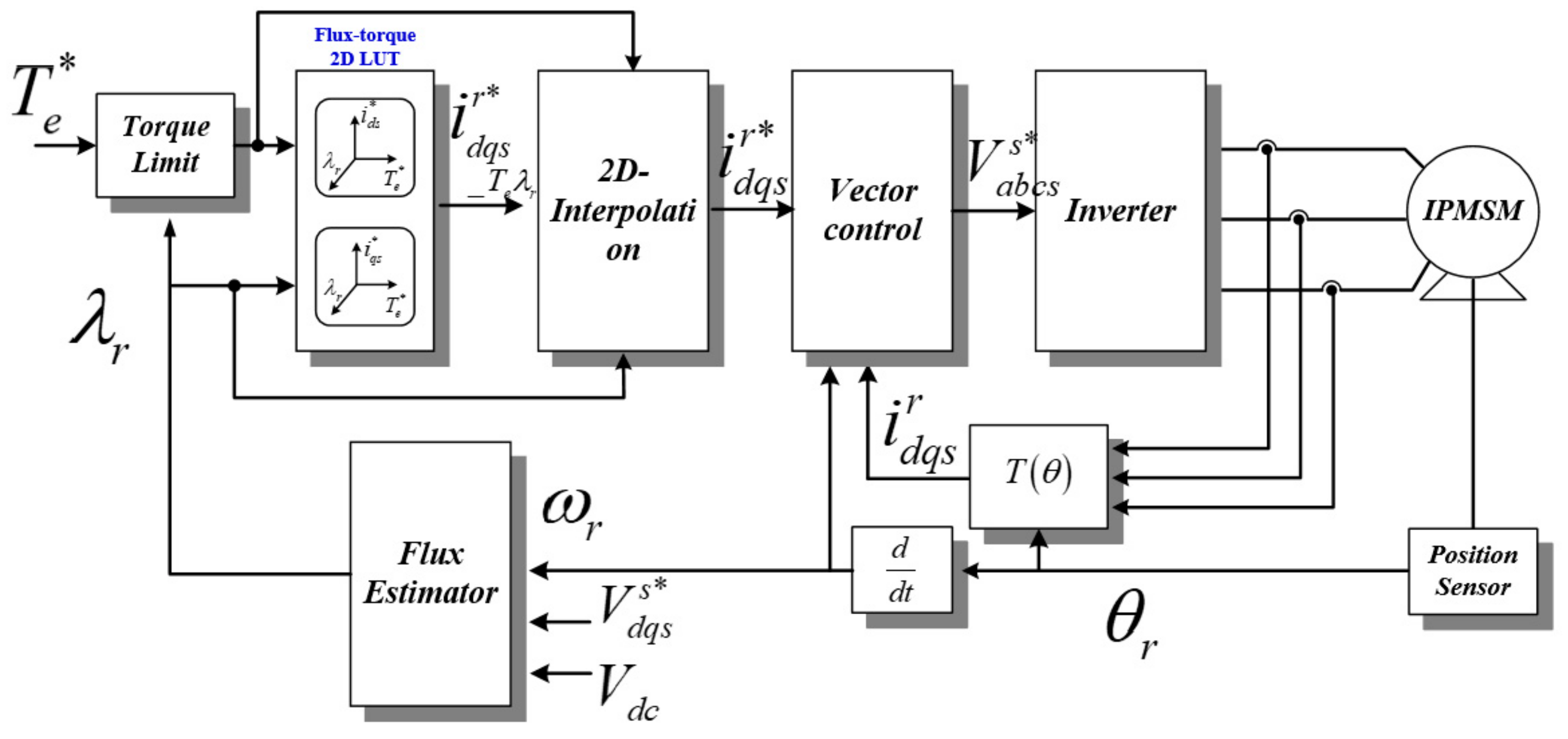
6]. Among these control methods, the flux-torque 2D-LUT based control method is the most generally used due to the reflection of DC-link voltage variation. This method is shown in
Figure 1 [
1].
In this controller, the current data in the 2D-LUT is stored according to the respective memory addresses corresponding to flux-torque values. Because the memory address is a discontinuous value, only current reference data for a specific flux and torque can be stored in the memory. Therefore, it is impossible to store the appropriate current data for the entire driving region. To solve this problem, two-dimensional interpolation has been used to properly interpolate input data that have not been previously stored in the memory [
7,
8,
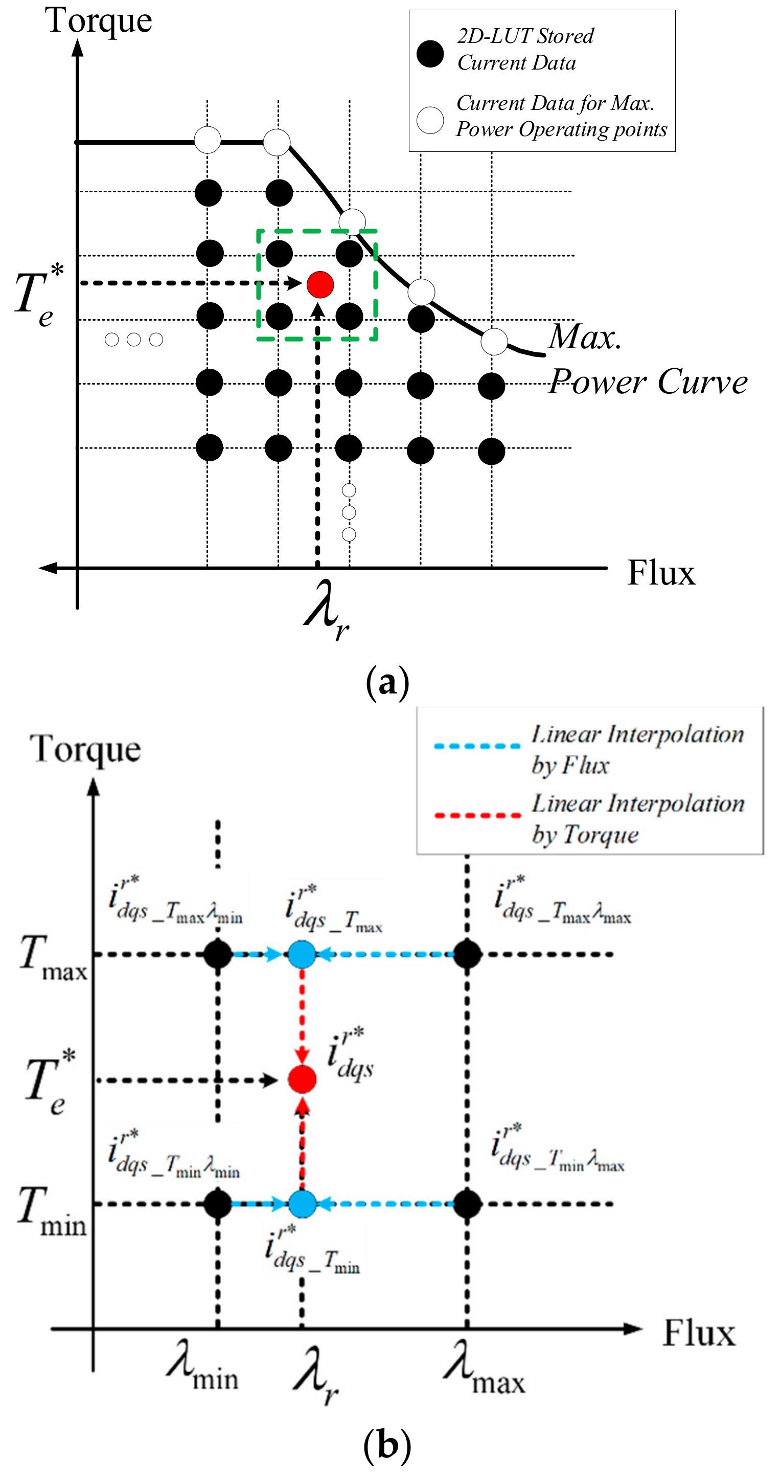
9]. Two-dimensional interpolation produces the linear outputs of two continuous input parameters that are not defined at the specific torque and flux points of the look-up table address from the discreet look-up table data. For instance, when the input parameters are inserted into a look-up table, related outputs are generated from memory. These outputs are then linearly interpolated using first-order Newton’s interpolation to calculate the approximate output for the input parameters.
Two-dimensional interpolation in PMSM control is only effective if the amount of stored data is sufficient to ignore the interpolation error. However, if the data is insufficient, the interpolation error cannot be ignored because all PMSM current trajectories are not linear, but ellipsoidal. Moreover, in automotive applications, in order to fulfill the international standard ISO26262, which aims to ensure driver safety, PMSM drives should have many fault diagnostic features and AUTOSAR software, which requires much memory to operate.
To solve this problem, only a few studies have investigated the problem of optimal memory use. Lenke et al. [
10] used curve fitting to reduce the amount of memory used. However, they did not suggest the solution for the error between the interpolated curve fitting output and optimal output. A constant torque control method for PMSMs using any table was demonstrated in [
11]. However, this method requires exact PMSM parameters. Moreover, if the target PMSM does not have sufficient saliency, its effectiveness is limited. Because current trajectories for PMSMs are ellipsoidal, the interpolation used in this application requires a second-order interpolation method, such as a second-order Lagrange or Spline interpolation with parameter modification for each operating condition [
12]. However, these are seldom used in motor control because of heavy calculation burdens to digital signal processors (DSPs).
This study proposes a novel control method to reduce this interpolation error. First, we will analyze the cause of the interpolation error and define the problem characteristics. Next, we will illustrate the compensation method for the interpolation error using DC-link voltage feedforward.
3. An Interpolation Error Compensation Method with DC-Link Voltage Feedforward Controller
Generally, because the magnitude of the current in the field weakening region is not large, the magnitude of the back EMF has a major influence on the components in the permanent magnet’s flux. Therefore, the variation in the torque in this region is largely affected by the variation in the q-axis current and the voltage restriction is greatly affected by the speed and the d-axis current. Among these, the speed is not a direct control target of the electric motor, but a restrictive condition that is influenced by the machine-driving environment. Therefore, to compensate for the reduced output caused by the interpolation, the q-axis current must be compensated to raise the torque.
This torque error occurs because the magnitude of the back EMF of the interpolated q-axis current is smaller than the voltage limit, which is determined by DC-link voltage. Therefore, the compensated q-axis current can be obtained from the voltage error between the back EMF and the voltage limit calculated from the DC-link voltage. From this error, the proportional-integral (PI) controller in this study deducts the compensated q-axis current [
13,
14].
where
and
are P and I gains of PI controller, respectively.
However, as all current trajectories for PMSM operation are ellipsoidal, the PI controller is insufficient to calculate the compensation current. A PI controller is widely known to be effective with fixed references. However, if the references are ellipsoidal, the final output value always has an error from delayed response.
The easiest way to respond suitably to ellipsoidal references is to use a proportional-integral-differential (PID) controller to increase the poles of the controller’s characteristic equation or to adapt numerous higher gains of PI controller to reduce this final output error. However, the D controller requires suitable filters to avoid divergent outputs and a higher gain PI controller can be very unstable operation for disturbance.
In this work, a feedforward controller was added to improve the dynamics of the PI controller. To obtain the feedforward compensation current, the voltage error between the back EMF and the voltage limit can be obtained as Equation (11) from Equation (7).
where
is voltage error from the interpolation.
As shown in
Figure 4, because the interpolated d-axis current reference generates a proper current for the voltage limit, Equation (11) can be changed to Equation (12).
To reduce this voltage error to zero, the compensation feedforward q-axis current can be established using Equation (13).
where,
is compensation feedforward q-axis current.
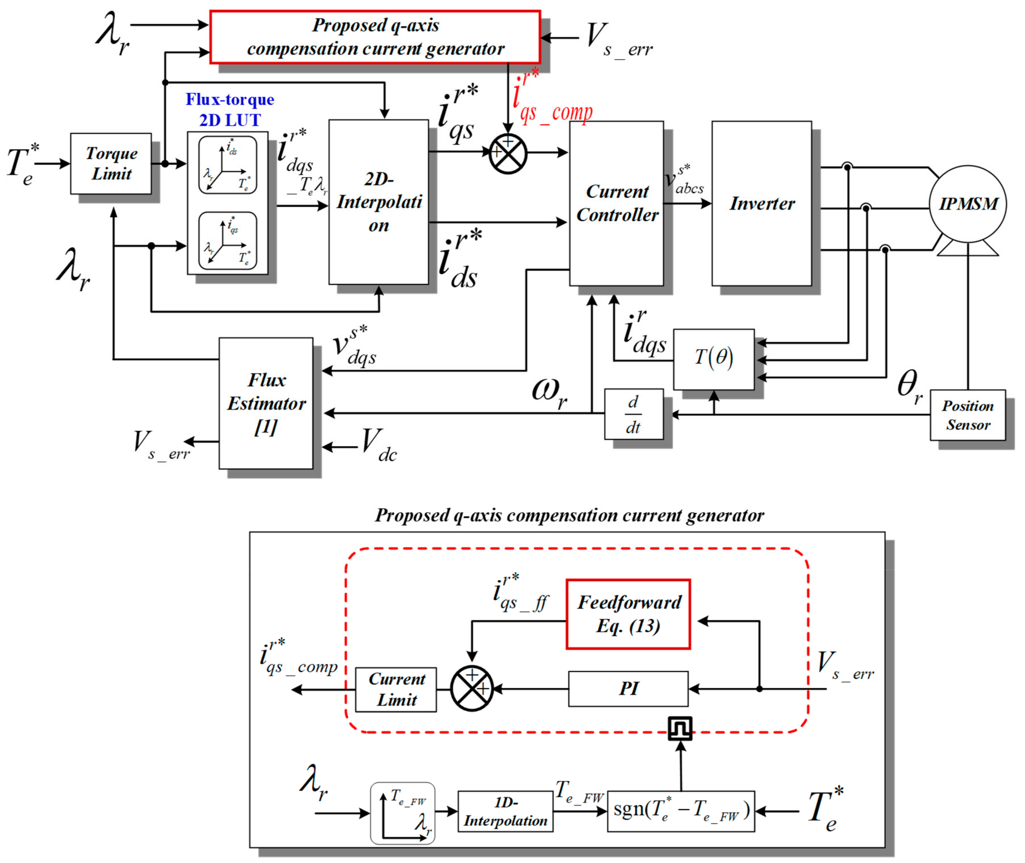
Using Equation (13), the proposed overall control block for q-axis compensation current is established in
Figure 5.
As mentioned, an interpolation error hardly exists in the constant torque operating region. Moreover, the back EMF in this region has its own value at each operating point. Compensating for interpolation error in this region requires other back EMF look-up table data for each flux and torque values. Therefore, in this work, the compensation block was deactivated while the PMSM operated in the constant torque region.
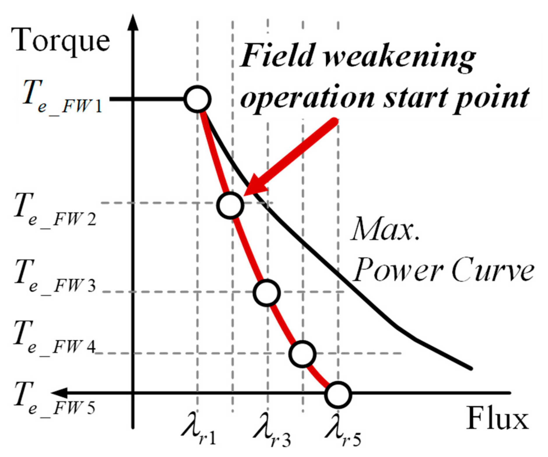
To reduce the amount of stored memory for voltage magnitude, the start points for the field weakening operation of each speed were obtained experimentally instead of from voltage magnitudes all over the operating region.
Figure 6 shows the stored data of field weakening start points. As can be seen from the figure, as speed increases, the generated torque reduces, generating a constant power output. In addition, because an error hardly occurs between the practical torque-speed curve and the linearly interpolated curve, the field weakening start torque, which is generated from flux-torque LUT of
Figure 5, can determine whether to enable or disable the compensation block. Instead of using speed inputs, estimated flux is used to reflect input voltage variation. Conversion from speed to flux can simply be obtained using Equation (14).
The activation condition of the q-axis current compensation can be determined by the following equation.
With this enable-disable control block, the proposed compensation block is only activated when the effect of compensation is maximized.
4. Experiment
To verify the proposed control algorithm, the experiment was set up as shown in
Figure 7. The test motor parameters are described in
Table 1. The controller of the inverter used the DSP TMS320F28335 from Texas Instruments Corporation.
Although this DSP has sufficient memory to store current 2D-LUT data, for the worse environment configuration, the current map is constructed using very little memory compared to the conventional method.
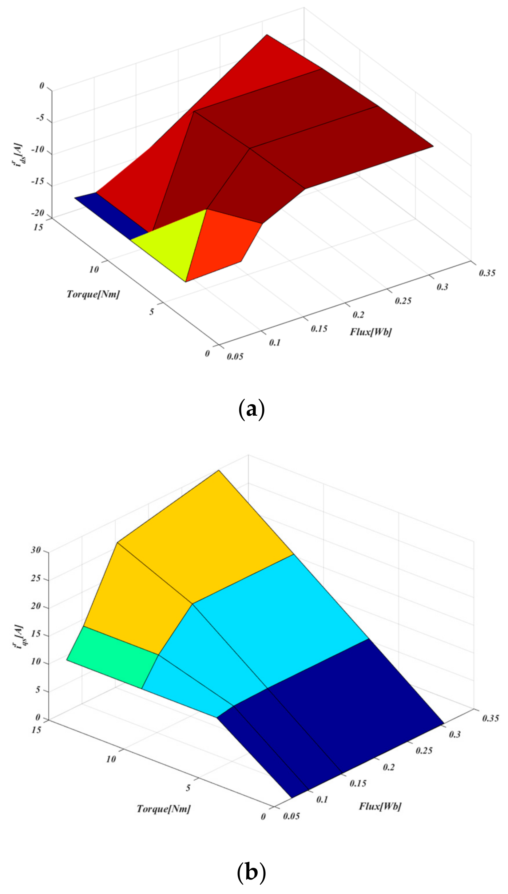
The d-q-axis current map for each speed-torque was measured through experiments [
6]. The results are shown in
Figure 8. In this study, the experimental current map was stored at one-third of the rated torque and at one-quarter of the maximum driving speed. The resulting speed-torque current map was transformed into a flux-torque map using Equation (14). As a result, it can be seen that only one torque data appears in the d-q-axis current value for the torque command change at the maximum speed, except for the d-q-axis current value during the zero-torque control. This is because the inductance expressed by the nominal value in the actual motor and the permanent magnet flux decreased due to the influence of saturation in the actual experiment.
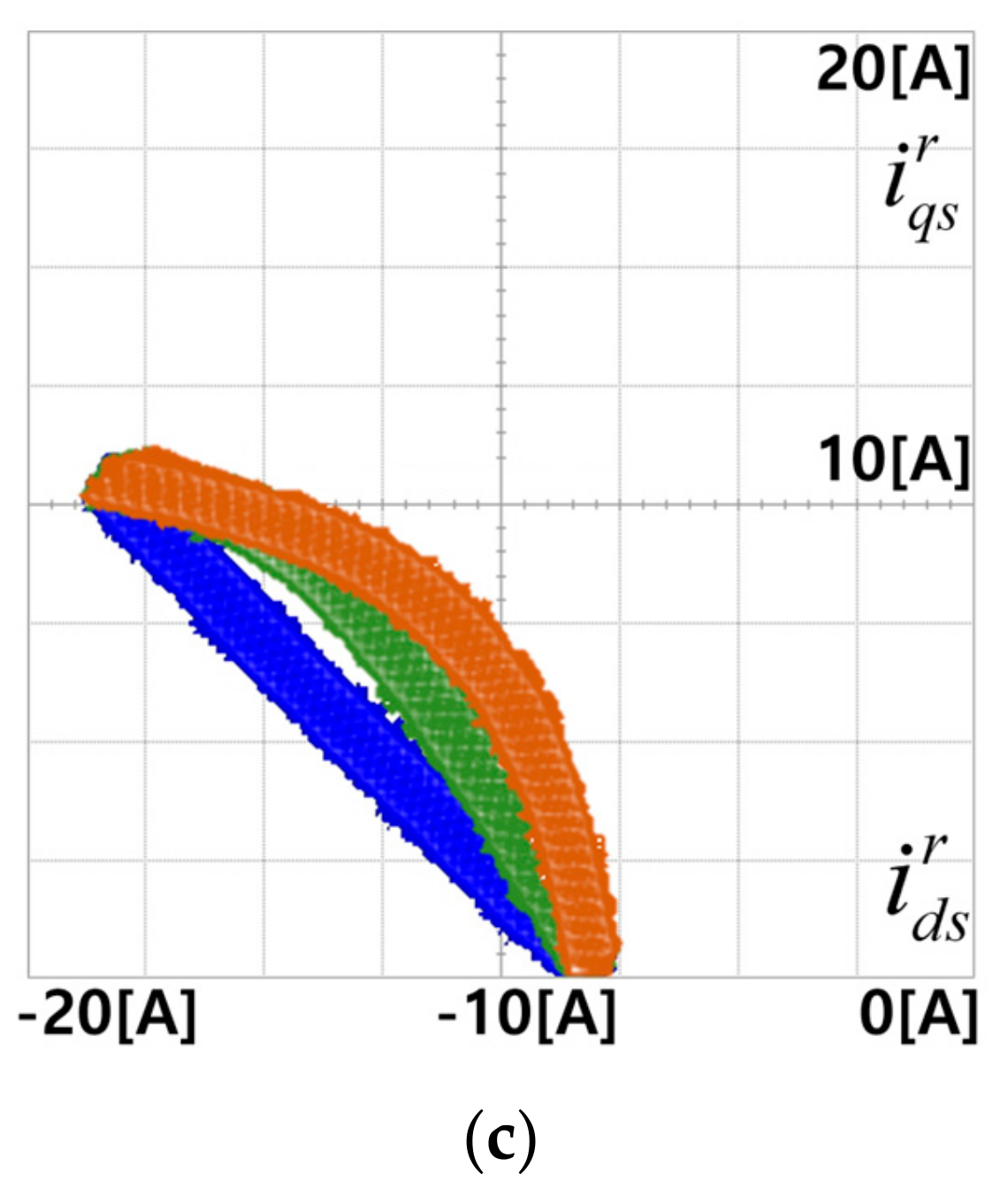
Figure 9 shows the comparison of experimental results with or without the proposed compensation method. Without the compensation method, the d-q-axis currents are linearly controlled due to the 2D interpolation according to the increase of torque references. Despite applying 2D interpolation, a considerable error exists between the maximum controllable output and linearly controlled output because the stored current references are insufficient in the high-speed field weakening operating region. However, with the proposed compensation method, the d-q-axis current trajectory follows the voltage limit ellipse, which means that the target PMSM generates the maximum controllable output at current motor speed.
Figure 10 shows the compared experimental results for operation at 1500 rpm. The applied torque reference is from 0 to 15 Nm. The shape of the torque reference is a ramp with a slope of 0.75 Nm/ms. As shown in
Figure 10a, without any compensation, the d-q-axis current references are linearly straight lines because the stored currents data have only two points at this speed. In
Figure 10b, for the compensation algorithm using only a PI controller [
14], the compensated amount is small and delayed because the voltage error is not fixed, but is varied according to the torque reference. The compensator requires time to generate suitable compensation currents. If the torque reference is changed rapidly, the response time of the PI controller must be considered because excessive q-axis current occurs and saturates the back EMF. In
Figure 10c, with the proposed feedforward compensator, the response time of the PI controller can be improved. Therefore, a suitable compensation current can be obtained, even if a rapid varied torque reference is applied.


