Abstract
This paper presents an improved droop-based control strategy for the active and reactive power-sharing on the large-scale Multi-Terminal High Voltage Direct Current (MT-HVDC) systems. As droop parameters enforce the stability of the DC grid, and allow the MT-HVDC systems to participate in the AC voltage and frequency regulation of the different AC systems interconnected by the DC grids, a communication-free control method to optimally select the droop parameters, consisting of AC voltage-droop, DC voltage-droop, and frequency-droop parameters, is investigated to balance the power in MT-HVDC systems and minimize AC voltage, DC voltage, and frequency deviations. A five-terminal Voltage-Sourced Converter (VSC)-HVDC system is modeled and analyzed in EMTDC/PSCAD and MATLAB software. Different scenarios are investigated to check the performance of the proposed droop-based control strategy. The simulation results show that the proposed droop-based control strategy is capable of sharing the active and reactive power, as well as regulating the AC voltage, DC voltage, and frequency of AC/DC grids in case of sudden changes, without the need for communication infrastructure. The simulation results confirm the robustness and effectiveness of the proposed droop-based control strategy.
1. Introduction
For long-distance transmission, Multi-Terminal High Voltage Direct Current (MT-HVDC) grids are utilized to transfer the generated power from offshore AC sources, e.g., wind farms, to onshore AC grids. The delivered power can be shared by the onshore AC grids with the aim of maintaining the DC voltage within a certain range at all the system buses. The power-sharing strategy depends on several objectives, such as power losses minimization, sharing ratio, and priority order [1]. Power-sharing and voltage control in MT-HVDC systems are the major challenges especially for the control and operation of the power system while it faces an outage [2,3]. Significant research studies are conducted on MT-HVDC system modeling [4,5,6,7,8,9,10,11,12,13,14,15] and control [16,17,18,19,20,21,22,23,24].
In AC/DC grids, two parameters should be considered: (1) The DC voltage at different buses for the DC grids to share the power. (2) The frequency for the AC grids to minimize the deviations in power, and among the other interconnected AC grids. There are several methods to perform the operation of power-sharing control and frequency and voltage regulation [17,18,20,21,22,23]. These control strategies can be classified into two main categories: (1) master-slave technique and (2) distributed DC voltage control strategy. In terms of sub-categories, both of them can be classified into centralized and decentralized control methods.
1.1. Master-Slave Technique
In order to control the DC voltage in MT-HVDC systems, the active power should be controlled considering one converter as the slack converter, while the other converters are controlling the active power at a constant level. The slack converter can control the DC voltage using the outer loop in the DC voltage controller. By performing Optimal Power Flow (OPF) at different buses, the setting for all the other converters can be calculated in the master converter. To ensure the operation within the acceptable limits of the converter, the master converter must be oversized and it needs a larger power rating. Moreover, a fast communication infrastructure between different nodes is required to improve the reliability of AC/DC grids [2,25,26]. In order to prevent the voltage of the entire system from violating the limits, the reference value for the DC voltage in the master converter should be defined. The master-slave technique has some drawbacks, which are mentioned as follows [25,26,27,28,29,30,31]:
- A high-speed communication infrastructure is required.
- Regulating voltage through the entire AC/DC grids is complicated through one converter.
- The outage of mater converter leads to DC over-voltage or under-voltage, and consequently collapse of the entire DC grids.
Figure 1 shows the active power-DC voltage () characteristics of a typical master-slave controller.
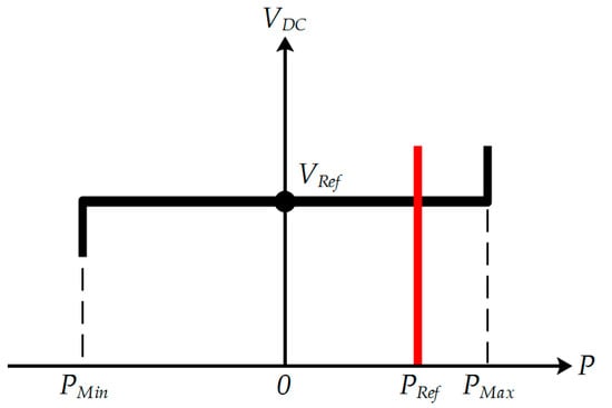
Figure 1.
characteristics of (black) the master converter and (red) the slaves.
In [32], a communication-free DC voltage control strategy for MT-HVDC systems is proposed. The configuration of the system is based on a grid-side master converter and a wind farm to incorporate and maintain the DC-link voltage in its acceptable range, as well as providing frequency support and improving the power dispatch. The control strategy uses the DC-link voltage at the master converter and maintains the wind power reserve. As a result, the wind farm can participate in the DC-link voltage control without the need for the communication infrastructure. The main drawback of this control strategy is that the outage/contingency at the master converter can cause instability of the entire AC/DC grids. In addition, since the other converters are injecting power to the MT-HVDC systems, AC/DC grids face with surplus/deficit injected power, and consequently, the DC voltage increases/decreases drastically. N-1 converter security analysis can improve the reliability of AC/DC grids.
To overcome the dependency of high-speed communication infrastructure and improve the reliability of AC/DC grids, the voltage margin method and voltage droop-based control method are proposed. The voltage margin method is a modified version of the master-slave technique to tackle the N-1 security problem and control the voltage through the voltage and active power of different converters in MT-HVDC systems [33,34,35,36,37,38]. The main drawbacks of this method are the complexity in terms of controlling several parameters and the large oscillations of power flow due to the sudden changes in the DC voltage [18]. In MT-HVDC systems, two or more converters are equipped with the DC voltage-droop controller to improve the reliability of AC/DC grids. The rest of the local terminals can operate in a constant power control mode. If any changes in the DC voltage are detected by a converter equipped with DC voltage droop-based controller, this controller can generate adequate deviation of of the converter and support the power balance on the DC grids and reduce the large DC voltage oscillations [7,16,39,40]. In practice, a high-accuracy of power balance in AC off-shore and on-shore AC system is mandatory. Hence, the droop parameters should be optimized according to the DC voltage changes [41]. In addition, the frequency changes generate adequate power deviation response of the converter and modify [17,39,41,42,43,44]. However, a global frequency-droop control strategy of the MT-HVDC system is required. In [45], a control strategy is proposed to emulate the pattern of the conventional AC generators when participating in the frequency regulation. The proposed frequency-droop control strategy can enable/disable different control loops, but it negates the action of any possible voltage-droop controller.
1.2. Distributed DC Voltage Control Strategies
To improve the stability of AC/DC grids, as well as increasing the accuracy of balancing the power, the distributed DC voltage control strategies, such as distributed direct DC voltage control and adaptive droop-based control are investigated. In these two techniques, a PI controller on the slack bus combines with the other PI controllers on the different local buses and regulates the DC voltage. By utilizing the communication infrastructure, the control parameters and reference values can be computed frequently and sent to a centralized supervisory controller, and then, sent to the other local converters.
1.2.1. Distributed Direct DC Voltage Control Strategy
Several research studies related to the distributed direct DC voltage control method are carried out [18,23,34,46,47,48,49,50]. Therefore, different OPF algorithms are proposed to minimize the losses and determine the reference value for the DC voltage of local direct DC voltage-controlled converters without the need for communication infrastructure. In addition, to analyze the operation of the power system, the proposed OPF techniques are used to study the contingency in one of the direct DC voltage-controlled converters and tackle the N-1 security problem. Considering the uncertainty in the generated power by the off-shore AC systems interconnected with the MT-HVDC systems to the power grids and the line resistance can reduce the accuracy of the OPF. Moreover, due to the direct relationship between the line resistance and the power balance and DC voltage, by losing the communication connections for a long time, the DC voltage deviations increase and it can cause instability of the entire AC/DC grids. As a result, protective equipment, such as dump resistors are required to prevent the excessive increase in the DC voltage level. As a matter of fact, the distributed direct DC voltage control is suitable for the AC grids, where no single power station is left alone to guarantee the stability of the system [46].
1.2.2. Adaptive Droop-Based Control Strategy
The droop control strategy for MT-HVDC systems can operate as in traditional AC grids, where the load-dependent frequency deviations can be used as an input signal for the control system and adjust the generated power to meet the demand [51,52]. An adaptive droop-based control strategy is a promising solution due to the disadvantage of distributed direct DC voltage control method to lose communication connections for a long time and lose the stability of AC/DC grids.
• Adaptive Power and DC Voltage Droop-Based Control Strategy
In MT-HVDC grids, the control system employs the droop setting to regulate the DC voltage within the system by adjusting the converter current in such a way that power balance is guaranteed [53,54,55,56]. The defined gain of the adaptive power and DC voltage droop-based controller can reduce the sensitivity of power balance to the line resistance, improve the accuracy of the OPF, and simultaneously, regulate the DC voltage. In addition, the corresponding parameters of the adaptive droop-based controller can be optimized for different operation objectives. In [56], a methodology to calculate the droop parameters of the droop-based converter to minimize the power losses in transmission lines in off-shore AC systems interconnected with the MT-HVDC systems is proposed. The main drawback of this method is its complexity to be applied to the ring or meshed grids [56]. In [27], the droop parameters of the droop-based converter are calculated in such a way that a certain power-sharing ratio between converters at contestant no-load voltage is achieved. However, the proposed method cannot be applied to the ring or meshed grids. In [7,16], a droop-based control method for the MT-HVDC systems in a decentralized operation is proposed. Nevertheless, the main drawback of the proposed droop-based control method is the fact that the sensitivity of power balance depends on the line resistance and it can cause inaccuracy of the OPF calculations. Increasing the voltage level in AC/DC grids with the aim of minimizing the transmission lines losses can lead to an increase in the converter losses. In order to minimize the transmission lines and converter losses, an OPF method to select the optimal reference values considering the fixed droop parameter for the DC voltage of the droop-based converter is proposed in [48]. Supporting energy adequacy, increasing off-shore AC system penetration, and maximizing converter loadability, as well as minimizing total losses, are the major priorities in the MT-HVDC system analysis. Another priority is the impact of droop parameters on the accuracy of the power balance and DC voltage dynamics [53,54]. Optimal DC voltage dynamics without violating the defined constraints is an important factor in the power balance which is considered in [31,50,53] in such a way that the droop parameters are selected by multiplying the local droop parameters by a multiplier. The accuracy of the power balance is the main drawback of the previous methodologies. Each converter has a particular available headroom to participate more in the DC voltage control. In [55], the available headroom of each converter is used to analyze the droop parameters and it is replaced with the new operating points after each contingency to improve the stability of AC/DC grids. The droop-based controllers’ parameters are selected optimally due to the sudden change in the reference values in [57]. The main drawback of this research study is neglecting power-sharing control.
• Adaptive Frequency and DC Voltage Droop-Based Control Strategy
In modern power systems, the significant contribution of Distributed Generations (DG) resources in the electricity generation and Plug-in Hybrid Electric Vehicles (PHEVs) in the load consumption are increasing gradually. Previously, the DG resources could not participate in the frequency regulation of AC grids the same as the conventional AC generators. Therefore, in order to participate in frequency regulation, a primary reserve sharing between AC grids and the candidate AC/DC converters is an important concern [39,43]. Using the frequency-droop based controller, the AC/DC converters can participate in the primary frequency regulation of the AC grids [17,42,43,44]. The deviation in power caused by the frequency-droop controller of the converter should adopt the standards of the power grids and it should be matched with the accurate values of the frequency deviation of the AC grids. The DC voltage-droop based controllers can be a solution to enforce the stability of the DC grid by optimizing voltage-droop controllers’ parameters, as well as regulating the DC voltage and balance the power. On the large-scale MT-HVDC system, optimizing frequency-droop based controllers’ parameters can adjust the frequency deviations and allow the MT-HVDC system to participate in the frequency regulation of the different AC systems interconnected by the DC grids. A control methodology to support the frequency of the system through the MT-HVDC systems by calculating the eigenvalues of AC/DC grids is proposed in [42]. In [58], the dead-band control is utilized for both frequency and DC voltage droop-based controllers. However, in both [42] and [58], the interactions among the frequency and DC voltage droop-based controllers are not considered. In [17], the primary frequency control of remote grids connected by MT-HVDC systems is studied to control the frequency-droop parameters and comply with the desired value for the predefined frequency deviation. An analytical methodology of the interactions among AC and DC grids is performed in [43] to utilize the frequency and DC voltage droop-based controllers and modify either the DC voltage dynamics or the frequency deviations. The same study as [43] is conducted in [39] with the aim of determining the interactions among DC voltage droop-based controller, to comply with the maximum DC voltage deviation constraints, and frequency-droop controller to allow the HVDC system to participate in the frequency regulation of AC grid. In [44], the interactions between frequency and DC voltage droop-based controllers through the evolution pattern of the frequency of each AC grids is studied. However, the correction of droop parameters to minimize the deviations in DC voltage and frequency is disregarded.
To address all the above-mentioned challenges, in this paper various control strategies of MT-HVDC systems are investigated and an improved droop-based power-sharing control strategy of MT-HVDC systems is proposed to improve the accuracy of the power flow control. The main contributions of this paper are as follows:
- To contribute the MT-HVDC system to the grid regulation, a generalized model of MT-HVDC systems topology and the steady-state interaction among MT-HVDC system and AC grids are investigated.
- An improved communication-free droop-based controller is proposed to enforce the stability of the DC grid, and allow the MT-HVDC system to participate in the grid regulation. A new strategy to control active and reactive power flow using the AC voltage-droop, DC voltage-droop, and frequency-droop controllers is proposed to manage the operational constraints of AC/DC grids. Moreover, an optimal tuning strategy is investigated to either optimize the controllers’ response time with the aim of enhancing the cut-off frequency or improve the system stability with the aim of less damping oscillation and overshoot percentage.
- Because of the nonlinear behavior of the MT-HVDC system, the corresponding parameters of the controllers of the Voltage-Sourced Converter (VSC)-High Voltage Direct Current (HVDC) stations in a decentralized structure are tuned to mitigate any changes in the frequency, AC voltage, and DC voltage and consequently, balance the instantaneous power share in the MT-HVDC system.
2. VSC-HVDC Station in MT-HVDC Systems
2.1. Control of the VSC-HVDC Station
The MT-HVDC system consists of several VSC-HVDC stations, which are connected to each other via the DC grids. The DC voltage level at each bus should be fixed or in a small window of maximum and minimum limits. Each terminal should be capable of adopting various control strategies depending on the system requirements [59]. Therefore, a proper VSC-HVDC system should be capable of monitoring and controlling both the AC-side and DC-side parameters. On the AC side and considering the type of the power grid connection, the VSC-HVDC station can operate in constant -mode or constant -mode. It is also possible to add -droop controller in the AC-bus control. On the DC side, the VSC-HVDC station can operate in constant -mode, constant -mode, or constant -mode. Considering the connected VSC-HVDC station to the AC generator(s) as the single power source in the AC grid, none of the DC parameters can be controlled.
There are different control modes of operation for VSC-HVDC stations, which are as follows.
2.1.1. Constant AC Voltage Control
The main objective of the constant control strategy is to maintain the level of the AC voltage at the Point of Common Coupling (PCC) constant. This strategy is utilized, when the connected VSC-HVDC station to the AC generator(s) is the single power source in the entire power grids. Therefore, the power flow is dependent on the grid structure and consequently, the active and reactive power flows are not decoupled. It should be noted that in this control strategy, there is no need for frequency control.
2.1.2. Constant Active Power-AC Voltage Control
In the long transmission lines, when the resistance () and inductance () are too high, the voltage drop across the line increases. As in the long transmission lines is not constant, the VSC-HVDC station should be capable of regulating the level of the AC voltage. Therefore, the control strategy is utilized, when both constant active power flow and AC voltage is required. The constant active power flow is achieved using the active power flow controller. comes from a central power dispatching VSC-HVDC station or sets by operators manually.
2.1.3. AC Voltage-DC Voltage Control
The control strategy is applied, when the transmission lines have a significant voltage drop and the aim is to regulate the level AC voltage, as well as the DC voltage, by the VSC-HVDC station. To control and , the reactive power flow controller and active power flow controller are required, respectively.
2.1.4. Active Power-Reactive Power Control
When the level of the AC voltage is constant by itself, the constant control strategy is required. In this control strategy, and are needed to be assigned for each VSC-HVDC station.
2.1.5. Reactive Power-DC Voltage Control
In the control strategy, the level of the AC voltage is constant by itself and there is the need for regulating the DC voltage. In addition, the generated reactive power can be consumed at the other buses in the AC grid.
2.1.6. Frequency Control
When the control strategy is applied, the VSC-HVDC station contributes to the aggregated frequency regulation (based on the specific droop characteristics) of the AC grid.
2.2. VSC-HVDC Station Configuration
Figure 2 illustrates the complete structure of a two-level VSC-HVDC station in the reference frame. A two-level VSC-HVDC station consists of a six-pulse bridge with Insulated-Gate Bipolar Transistors (IGBTs) and parallel diodes. Using parallel diodes in the opposite direction enables power flow in either direction. The transformer in the AC side transforms the level of the AC voltage into a level, which is suitable for the converter. A passive filter should be used to minimize the AC voltage ripples and isolate the harmonics in the current due to the IGBT switching away from the AC grid. It should be noted that the shunt capacitance and resistance, and the series inductance of the DC grids are neglected. The DC capacitor can minimize the DC voltage ripples. For the long transmission lines, only the series resistance should be considered for the DC links. The VSC-HVDC station consists of a three-phase switch-mode converter and uses the Pulse Width Modulation (PWM) technique to control its phase voltage [60].
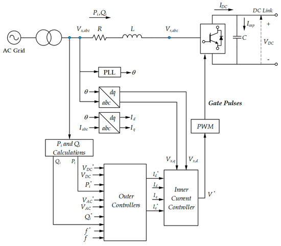
Figure 2.
The complete structure of a two-level VSC-HVDC station.
2.3. VSC-HVDC Station Operation
The inner current controller, shown in Figure 2, is equipped with a Phase Lock Loop (PLL) to instantaneously determine the phase angle and frequency. Furthermore, the inner current controller depends on the synchronously rotating reference frame for observing all the AC voltage and current quantities involved in the VSC-HVDC stations. As shown in Figure 2, the inner controller should be fed by the outer controllers. Considering the control mode, the outer controllers provide the reference current to the VSC-HVDC station. Moreover, the inner current controller prevents overloading during faults and evaluate the voltage drop on the AC side.
In order to analyze the operation of the VSC-HVDC station and considering that the converter is connected to an AC grid, the voltage on the AC side of the VSC-HVDC station can be calculated by applying the Kirchhoff’s Voltage Law (KVL) as follows:
where is the voltage on the AC side, is the input voltage of the converter, is the injected current to the converter, and and are the resistance and inductance between the converter and the AC grid, respectively.
Neglecting the power losses, on the steady-state, the DC-side active power is equal to the AC-side active power. Therefore,
To achieve a decoupled control of active and reactive power, Equation (1) should be transferred to the reference frame using the Park’s transformation, as follows:
The input voltage of the converter in the reference frame is as follows:
The AC current passing through the resistance and inductance is as follows:
The voltage across the inductor in Equation (1) should be applied to each current separately. Moreover, the time derivative of the voltage of the inductor in the reference frame requires to consider , where ω is the angular frequency of the fundamental component in the AC grid. Therefore,
The two parts in Equation (6) are the two expressions that can describe the current of the AC side of the converter, as follows:
and,
The apparent power of the VSC-HVDC station can be written as follows:
The active power injected to (and/or absorbed from) the AC grid is as follows:
The inner controller of the VSC-HVDC station can be implemented using Equation (1), which includes minimizing the inductance effect by a feedforward crossing term in the controller term. Using the PI controller, the dominant poles of VSC-HVDC station can be canceled by zeros of the PI controller. The nonlinear term in Equation (1) causes the static error at the steady-state. Therefore, using the PI controller with the feedback of the instantaneous value of and , both current vectors can be regulated. Correspondingly, the nonlinear term can be traced by and in the inner control loop with and . It should be noted that and are the reference current of the -axis and -axis current controllers, respectively.
and,
Substituting Equations (11) and (12) in Equation (1), the inner current controller loops of the VSC-HVDC station can be expressed as follows:
This method is called the decoupled current control strategy.
At the same time, two of the following types of the outer controller can be applied to control the VSC-HVDC station.
• Active Power Flow Controller
The reference frame is selected in a direction such that the -axis is in the same phase as the voltage of the AC source. Therefore,
Hence, Equation (10) can be rewritten as follows:
Equation (15) suggests that the active power flow can be controlled using , and correspondingly, the output of the active power flow controller is .
• DC Voltage Controller
Neglecting the converter losses and considering as the power transferred from the AC side to the DC side, and and as the power flowing into the DC grid and the DC capacitor, respectively, the active power balance of VSC-HVDC station can be written as follows:
where,
and,
Accordingly,
Therefore, the differential equation of the DC voltage can be rewritten as:
where is the capacitance of the DC-link capacitor.
Equation (20) shows that the DC voltage can be controlled using . Although can be represented as a feedforward control in the DC voltage controller, the DC voltage can be controlled without using a feedforward control loop. The reason is that the PI controller is capable of maintaining the DC voltage constant.
According to the above-mentioned explanations, Figure 3 shows the complete block diagram of the active power flow and DC voltage controllers of the VSC-HVDC station.
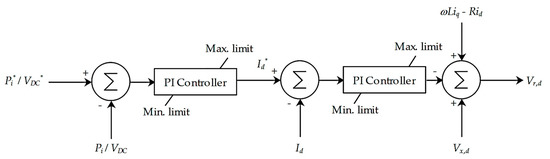
Figure 3.
The complete block diagram of the active power flow and DC voltage controllers.
• Reactive Power Flow Controller
Reactive power flow equation can be written as follows:
Equation (21) suggests that the reactive active power flow can be controlled using . As a result, the output of the reactive active power controller is .
• AC Voltage Controller
The same as the DC voltage control, the AC voltage can be controlled using the reference and measured AC voltage signals. The output of this controller is . In addition, the AC voltage can be controlled with a feedforward control loop. Figure 4 demonstrates the complete block diagram of the reactive power flow and AC voltage controllers of the VSC-HVDC station.
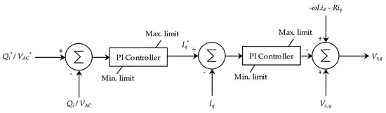
Figure 4.
The complete block diagram of the reactive power flow and AC voltage controllers.
It should be noted that equipping the outer controllers with the droop-based controllers balances the power and enforces the stability of MT-HVDC systems.
• DC Voltage-Droop Controller
The -droop control strategy is applied, when two or more VSC-HVDC stations in MT-HVDC systems have to regulate the DC voltage according to their predetermined -droop characteristics. In other words, the -droop control strategy enables instantaneous balancing power in the DC grids.
where is the reference power deviation generated by the -droop controller, is the reference voltage, and represents the -droop parameter (.
shows the power injection from the DC grid to the AC grid.
• Frequency-Droop Control
A converter equipped with the -droop controller participates in the frequency regulation of the AC grid that it is connected to and modifies the according to its predetermined -droop characteristics.
where is the reference power deviation generated by the -droop controller, is the reference frequency, and is the -droop parameter (.
shows the power injection from the DC grid to the AC grid.
The Power Factor (PF) of the VSC-HVDC station should always be close to one to synchronize the power transfer into the AC grid. Synchronizing the AC voltage of the converter with the AC voltage of the grid and comparing it with zero (as the steady-state error in reference voltage in the -axis) leads to Equation (14). Using the PLL, the displacement angle between the Clark and Park vectors can be obtained and consequently, the frequency of the AC voltage of the converter becomes equal to the frequency of the AC grid. It should be noted that to transform from the three-phase voltage into the reference frame, the displacement angle is needed for matrix multiplication. Figure 5 shows the extraction of the displacement angle from the three-phase voltage. Technically, a complete PLL has three back-to-back components, which are the voltage-controlled oscillator, the phase detector, and the loop filter.
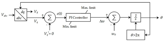
Figure 5.
The PLL control diagram.
3. Proposed Droop-Based Control Strategy for MT-HVDC Systems
3.1. Proposed Droop-Based Control System
Figure 6 and Figure 7 show the proposed droop-based control strategy for MT-HVDC systems, in which and can be obtained from the two outer controllers. The combination of the droop-based controllers provides a strong DC grid, balances the power, regulates the frequency, and improves the overall stability of the MT-HVDC systems.
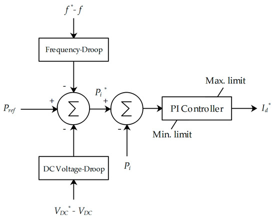
Figure 6.
The proposed droop-based outer controller to obtain .
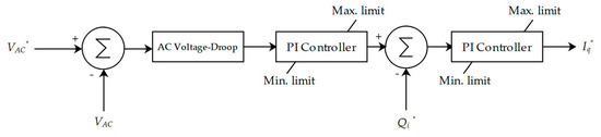
Figure 7.
The proposed droop-based outer controller to obtain .
3.2. Optimal Tuning of the PI Controllers
Optimal performance of the control loops is achieved by optimal tuning the PI controllers. This leads to a faster response of the system and minimizing the damping oscillations. To increase the cut-off frequency,, of the control loops (with low-order transfer functions), the Modulus Optimum Technique (MOT) is used. Considering a dominant and minor pole in the transfer function, the MOT selects the integral time constant of the PI controller to cancel out the dominant pole.
The Open Loop Transfer Function (OLTF) of the inner current loop is given as follows:
where and are the proportional gain and time constant of the PI controller, respectively. denotes the Laplace operator, is the time constant, and is the time delay of the converter (due to the sinusoidal PWM technique), where is the switching frequency of the converter.
is required to cancel the dominant poles in the external control system. Moreover, considering , and , any noise and interference from the switching frequency components can be avoided.
As the unity gain at is required, Equation (25) can lead to determining the proportional gain of the PI controller given in Equation (26).
The OLTFs of the DC voltage control loop, active and reactive control loop, and AC voltage control loop are given in Equations (27)–(29), respectively.
where is the total time delay ().
Assuming a pole of the OLTF close to the origin or at the origin by itself, the MOT cannot be applied to the control system, and instead, the Symmetrical Optimum (SO) method is used for specifying the PI controllers. The SO method can maximize the phase margin.
Considering the OLTF of the DC voltage control loop, the phase angle of the DC voltage control loop is given as follows:
where is the phase margin.
Differentiating the phase margin with respect to the cut-off frequency leads to the following equation.
Considering , , the phase angle of can be written as follows:
and accordingly,
Therefore,
Equation (34) results in the integral time constant as follows:
where is constant number.
As the unity gain at is required, therefore,
Hence,
3.3. Operation of the Proposed Droop-Based Control System
3.3.1. Principle and Operation of the Droop-Based Controllers
Assume the level of the DC voltage in the DC grid decreases. Therefore, the DC voltage-droop controller modifies the amount of power by the VSC-HVDC station. This modification decreases the frequency of the AC grid connected to the VSC-HVDC station and the frequency-droop controller opposed the action of the DC voltage-droop controller and regulates the frequency of the AC grid.
Considering converters in an MT-HVDC system, then,
Assuming an outage of a power generation unit or a significant change in the load level, the active power deviation of all converters equipped with the proposed droop-based control strategy based on their reference values is as follows:
As the variation of the power losses is disregarded and due to the fact that the converter equipped with the DC voltage-droop controller balances the power of the DC grid, therefore, , and the following equation is obtained.
In other words,
Therefore, the effective active power deviation for the converter of the MT-HVDC system is as follows:
Equation (42) shows the effective active power deviation generated by the frequency-droop controller of the converter of the MT-HVDC system. In addition, the contribution of the converter of the MT-HVDC system participating in the DC voltage regulation of the DC grid depends on .
Considering a fault on the AC grid and converters are connected to the faulty AC grid, as the frequency should be regulated throughout the entire system, the effective active power deviation can be written as follows:
Assume there is only one VSC-HVDC station connected to the faulty AC grid. Therefore, Equation (43) can be rewritten as follows:
Equation (44) shows that the effective frequency-droop parameter, , which is the ratio of the frequency-droop parameter and the active power deviation for the converter of the MT-HVDC system, is not equal to the initial frequency-droop value. Therefore,
In addition, the AC voltage-droop controller modifies the level of the AC voltage in the AC grid. The reactive power deviation of all converters equipped with the proposed droop-based control strategy based on their reference values is as follows:
3.3.2. Impact of the Droop-Based Controllers’ Limits
There are limits for the proposed droop-based controller. In other words, the droop controller’s limits prevent the active power deviation generated by the DC voltage-droop controller, the active power deviation generated by the frequency-droop controller and the reactive power deviation generated by the AC voltage controller of the converter of the MT-HVDC system from becoming higher than , , and , respectively. Therefore,
where for , is defined as follows:
In normal operation condition of the MT-HVDC system,
Therefore, neglecting the possible variation of the active and reactive power losses for converters, Equation (49) can be written as follows:
Assume converters are reached . Then, Equation (50) can be written as follows:
Considering the converter of the MT-HVDC system (), and and , substituting Equation (51) in Equation (49) leads to the following equation.
where,
If the maximum power deviation of the converter of the MT-HVDC system with regards to the frequency is not reached, the following equation can be derived.
Based on the above-mentioned explanations, the coupling between the DC voltage-droop and frequency-droop controllers leads to dynamically modifying their droop parameters. This also induces a modification of the dynamics of the MT-HVDC system.
It should be noted that the AC voltage-droop controller is independent and the active power deviation generated by the other droop controllers has no impact on it. The same strategy as the DC voltage-droop control without the frequency terms is valid for the AC voltage-droop controller.
4. Results and Discussions
To validate the performance of the proposed droop-based control system, a five-terminal MT-HVDC system consisting of five VSC-HVDC stations connected to different types of AC systems is modeled in PSCAD/EMTDC and MATLAB software. Figure 8 shows the configuration of the studied five-terminal MT-HVDC system.
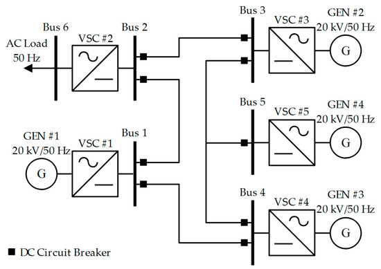
Figure 8.
The configuration of the studied five-terminal MT-HVDC system.
For all VSC-HVDC stations, , , and . The switching frequency in all VSC-HVDC stations is set to 5 kHz. The DC links between the VSC-HVDC stations are represented by series resistances of 0.01 . To protect the DC grids against the DC faults, two hybrid DC circuit breakers are installed at both ends of each DC link [61].
It is considered that VSC-HVDC stations #1, #2, #3, #4, and #5 are operated in constant DC voltage, constant AC voltage, constant active power, constant active power-AC voltage, and constant DC voltage control modes. It should be noted that VSC-HVDC station #1 is in converter mode ( control (negative power)), VSC-HVDC station #2 is in inverter mode (constant control (positive power)), VSC-HVDC station #3 is in inverter mode (constant control (positive power)), VSC-HVDC station #4 is in converter mode and ( control (negative power)), and VSC-HVDC station #5 is in inverter mode ( control (positive power)).
For all the PI controllers of the inner current controllers, the proportional gain and integral time constant are set to 4 and 0.0133, respectively. For VSC-HVDC station #1, the proportional gain and integral time constant of the outer current controller (reactive power controller) are set to −0.43 and 0.0267, respectively. For VSC-HVDC station #2, the proportional gain and integral time constant of the outer current controller (AC voltage regulator) are set to 3 and 0.05, respectively. For VSC-HVDC station #3, the proportional gain and integral time constant of the outer current controllers are set to 0.43 and 0.0267 (for active power controller) and −0.43 and −0.0267 (for reactive power controller), respectively. For VSC-HVDC station #4, the proportional gain and integral time constant of the outer current controllers are set to 0.43 and 0.0267 (for active power controller), 50 and 0.005 (for AC voltage regulator) and −0.43 and −0.0267 (for reactive power controller), respectively. For VSC-HVDC station #5, the proportional gain and integral time constant of the outer current controllers are set to 50 and 0.005 (for the AC voltage regulator) and −0.43 and −0.0267 (for the reactive power controller), respectively.
The initial settings of the system are , , , and . It is assumed that at , a load of 20 MVA at1 PF is switched on at Bus 6. Then, at , an additional load of 11.4 MW at 0.8 PF is switched on at Bus 6. After that, at , is set to −50 MW (rectifier mode). Then, At , is set to 40 MW (inverter mode). At , is set to 30 MVAR (reactive power generation). To check the stability of the system, the VSC-HVDC station #1 is disconnected from the system at , and lastly, at , the VSC-HVDC station #3 is disconnected from the system. To check the performance of the studied system, different scenarios are investigated.
4.1. Scenario 1: The Case Study with Four VSC-HVDC Stations
In the first scenario, it is assumed that the VSC-HVDC station #5 is disconnected from the entire system. This is done by keeping the DC breaker at Bus 5 open for the entire simulation time. Therefore, the VSC-HVDC station #1 solely controls the DC voltage in the entire system. Figure 9, Figure 10, Figure 11 and Figure 12 show the DC voltage, AC voltage, active power flow, and reactive power flow of the system when the VSC-HVDC station #5 is disconnected from the grid.
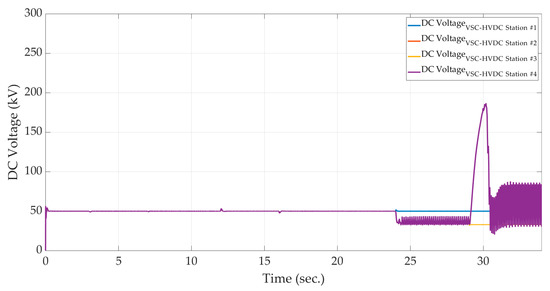
Figure 9.
The DC voltage profile of different VSC-HVDC stations in the first scenario.
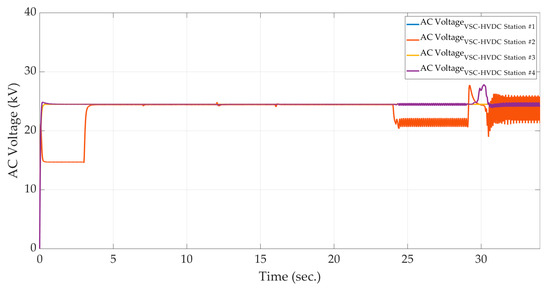
Figure 10.
The AC voltage profile of different VSC-HVDC stations in the first scenario.
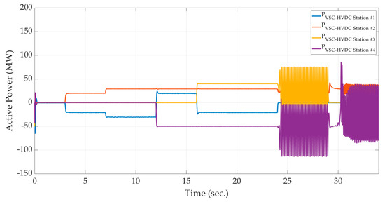
Figure 11.
The active power profile of different VSC-HVDC stations in the first scenario.
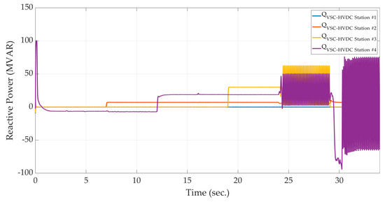
Figure 12.
The reactive power profile of different VSC-HVDC stations in the first scenario.
As the simulation results demonstrate when the VSC-HVDC station #1 is disconnected from the grid at , there is not enough power supply and therefore, the level of the DC voltage drops from 50 kV to approximately 36 kV. In addition, the disconnection of the VSC-HVDC station #3 from the grid at results in excess power inflow into the MT-HVDC system and in turn leads to increasing the level of the DC voltage from 50 kV to 185 kV. The large and continuous deviations in power flow result in deviations in the voltage and frequency and consequently, decreasing the overall stability of the grid [62,63]. The large oscillations shown in Figure 9, Figure 10, Figure 11 and Figure 12 show that without considering a backup VSC-HVDC station to regulate the DC voltage, the entire system becomes unstable.
4.2. Scenario 2: VSC-HVDC #5 Contribution to the DC Voltage Regulation
In the second scenario, it is assumed that the VSC-HVDC station #5 is connected to the grid to contribute to the DC voltage regulation. Therefore, the reference inputs of the DC voltage controller at VSC-HVDC stations #1 and #5 are the same.
The combination of the DC voltage-droop control and DC margin control enables the power-sharing among VSC-HVDC station in the DC voltage control mode based on a predefined participation factor for each station. The participation factor determines the active power rectified/inverted by a VSC-HVDC station as a fraction of the total power demand/supply in the MT-HVDC system to maintain the level of the DC voltage constant.
For number of VSC-HVDC stations in the DC voltage-droop control mode, the participation factor () of the VSC-HVDC station can be calculated as follows:
where and are the proportional gains of the and VSC-HVDC stations in the DC voltage control mode, respectively.
As only VSC-HVDC stations #1 and #5 regulate the DC voltage, it is assumed that the participation factors of the VSC-HVDC station #1 and #5 are 67% and 33%, respectively.
Accordingly,
In other words, the following droop setting for the VSC-HVDC station #5 should be considered.
Figure 13, Figure 14, Figure 15 and Figure 16 show the DC voltage, AC voltage, active power flow, and reactive power flow of the system, respectively, when the DC voltage reference setting of VSC-HVDC stations #1, #3, #4, and #5 is 50 kV and the participation factors of the VSC-HVDC stations #1 and #5 are 67%, and 33%, respectively.
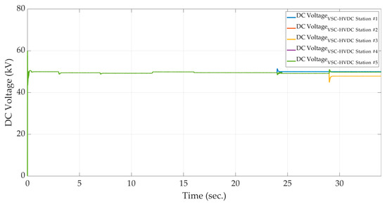
Figure 13.
The DC voltage profile of different VSC-HVDC stations in the second scenario.
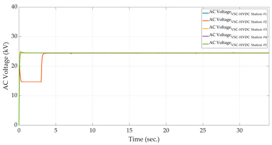
Figure 14.
The AC voltage profile of different VSC-HVDC stations in the second scenario.
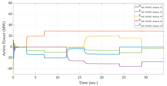
Figure 15.
The active power profile of different VSC-HVDC stations in the second scenario.
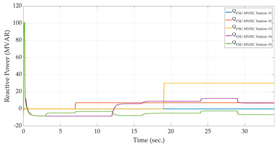
Figure 16.
The reactive power profile of different VSC-HVDC stations in the second scenario.
As shown in Figure 13, although the DC voltage of the MT-HVDC system is affected by the disconnection of VSC-HVDC station #1 at and the disconnection of VSC-HVDC station #3 at , the steady-state DC voltage is kept within the acceptable range.
Compared to the previous scenario, as there are two VSC-HVDC stations to regulate the DC voltage, the disconnection of the VSC-HVDC stations #1 at and the disconnection of the VSC-HVDC stations #3 at do not prevent power-sharing in AC/DC grids. Therefore, the system remains stable.
4.3. Scenario 3: Equipping VSC-HVDC #4 with the Proposed Droop-Based Controller
In the third scenario, it is assumed that VSC-HVDC station #5 is connected to the grid to contribute to the DC voltage regulation and VSC-HVDC station #4 is equipped with the proposed droop-based controller. Hence, the reference inputs of the DC voltage controller at VSC-HVDC stations #1, #4, and #5 are the same. For VSC-HVDC station #4, the proportional gain and integral time constant of the outer current controllers are set to 0.43 and 0.0267 (for the active power controller), 50 and 0.005 (for AC voltage regulator) and −0.43 and −0.0267 (for the reactive power controller), respectively.
Figure 17, Figure 18, Figure 19 and Figure 20 demonstrate the active power flow, reactive power flow, DC voltage, and AC voltage of the system, respectively, when the DC voltage reference setting of VSC-HVDC stations #1, #3, #4, and #5 is 50 kV and the DC voltage-droop settings of the VSC-HVDC stations #1, #4, and #5 are –2, −0.0001, and –1, respectively. In addition, the frequency and AC voltage-droop settings are set to 0.001 and −0.0001, respectively.
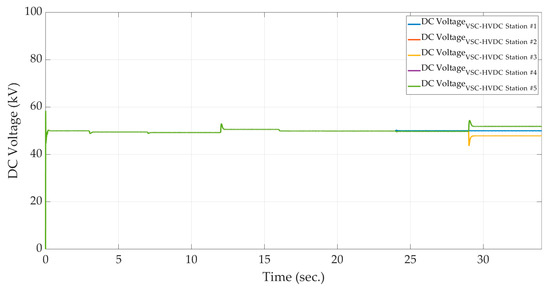
Figure 17.
The DC voltage profile of different VSC-HVDC stations in the second scenario.
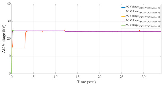
Figure 18.
The AC voltage profile of different VSC-HVDC stations in the third scenario.
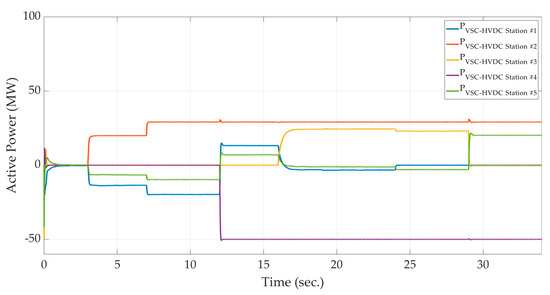
Figure 19.
The active power profile of different VSC-HVDC stations in the third scenario.
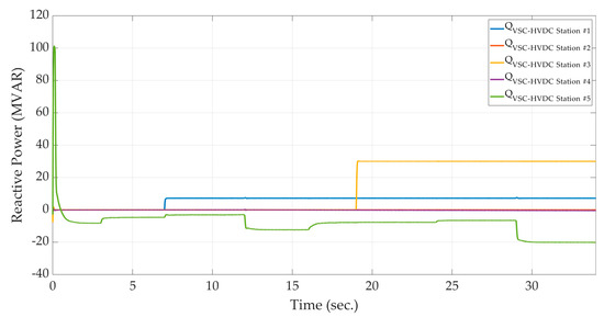
Figure 20.
The active power profile of different VSC-HVDC stations in the third scenario.
According to the obtained result, changing in the droop settings leads to changes in the power flow and overall stability of the system. Based on Figure 15, the dominant VSC-HVDC station to supply the active power is the VSC-HVDC station #1. However, employing the proposed droop-based controller leads to supplying the majority of the active power by VSC-HVDC station #4.
It should be noted that any changes in the frequency of the AC grid and DC voltage in the DC grid are regulated by injecting active power to the grid. In addition, the AC voltage regulation is performed by injecting reactive power to the grid. As shown in Figure 17, the oscillations in the DC voltage profile after disconnection of VSC-HVDC station #1 at and the disconnection of VSC-HVDC station #3 at are regulated by injecting active power by VSC-HVDC stations #2, #3, and #4. According to the obtained result, the main aim, which is the simultaneous regulation of the frequency, AC voltage, and DC voltage at Bus 4, is achieved.
In order to check the impact of modifying the droop settings of the proposed droop-based controller on the active and reactive power flow, different cases are investigated, as shown in Table 1. In Table 1, case 1 is the reference case that is studied in Section 4.3. Figure 21 and Figure 22 show the active and reactive power flow of the VSC-HVDC station #4, which is equipped with the proposed droop-based controller, after changing the droop settings based on Table 1.

Table 1.
Different droop parameters of VSC-HVDC station #4.
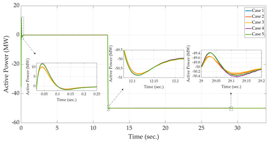
Figure 21.
The impact of modifications of droop settings on the active power profile of VSC-HVDC station #4 in the third scenario.
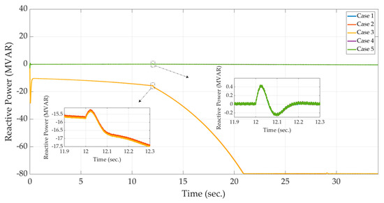
Figure 22.
The impact of modifications of droop settings on the reactive power profile of VSC-HVDC station #4 in the third scenario.
5. Conclusions
In this paper, an improved droop-based control strategy for the active and reactive power-sharing on the large-scale Multi-Terminal High Voltage Direct Current (MT-HVDC) systems is proposed. The equivalent circuit of the Voltage-Sourced Converter (VSC)-HVDC station in the reference frame is established and employed for developing an improved droop-based control strategy for the VSC-HVDC station. The proposed droop-based control strategy is a communication-free control method in which its droop parameters, consisting of AC voltage-droop, DC voltage-droop, and frequency-droop parameters, are selected optimally. The proposed droop-based control strategy is applied to a five-terminal MT-HVDC system to control both the AC and DC grids for a stable-steady state and dynamic performance. In addition, different control strategies of the VSC-HVDC station are investigated in this paper. Modifications on the droop settings are also performed. The simulation results illustrate that the proposed droop-based control strategy not only results in a stable steady stated and dynamic operation of the MT-HVDC system but also is capable of restoring operation during the loss of DC voltage regulating VSC-HVDC station without the need for communication infrastructure. The simulation results validate the robustness and effectiveness of the proposed droop-based control strategy.
Author Contributions
F.M. was responsible for methodology, collecting resources, data analysis, writing—original draft preparation, and writing—review and editing. G.-A.N. and M.S. were responsible for the supervision, and writing—review and editing. All authors have read and agreed to the published version of the manuscript.
Funding
M. Saif acknowledges the financial support of Natural Sciences and Engineering Research Council (NSERC) of Canada, as well as National Science Foundation of China under grant number 61873144.
Conflicts of Interest
The authors declare no conflicts of interest.
Abbreviations
| Reference active power | |
| Active power | |
| DC voltage | |
| AC voltage | |
| Reference reactive power | |
| Reactive power | |
| DC current | |
| Frequency |
References
- Xu, L.; Williams, B.; Yao, L. Multi-terminal DC Transmission Systems for Connecting Large Offshore Wind Farms. In Proceedings of the IEEE Power Energy Society General Meeting Conversion and Delivery of Electrical Energy 21st Century, Pittsburgh, PA, USA, 20–24 July 2008. [Google Scholar]
- Liang, J.; Jing, T.; Gomis-Bellmunt, O. Operation and Control of Multi-terminal HVDC Transmission for Offshore Wind Farms. IEEE Trans. Power Deliv. 2011, 26, 2596–2604. [Google Scholar] [CrossRef]
- Aragues, M.; Egea, A.; Gomis, O.; Sumper, A. Optimum Voltage Control for Loss Minimization in HVDC Multi-Terminal Transmission Systems for Large Offshore Wind Farms. Electr. Power Syst. Res. 2012, 89, 54–63. [Google Scholar] [CrossRef]
- Meah, K.; Sadrul Ula, A.H.M. Simulation Study of the CIGRE HVDC Benchmark Model with the WSCC Nine-bus Power System Network. In Proceedings of the 2009 IEEE/PES Power Systems Conference and Exposition, Seattle, WA, USA, 15–18 March 2009. [Google Scholar]
- Van Hertem, D.; Ghandhari, M. Multi-terminal VSC HVDC for the European Supergrid: Obstacles. Renew. Sustain. Energy Rev. 2010, 14, 3156–3163. [Google Scholar] [CrossRef]
- Wang, F.; Bertling, L.; Le, T. An Overview Introduction of VSC-HVDC: State-of-Art and Potential Applications in Electric Power Systems. In Proceedings of the CIGRÈ International Symposium, Bologna, Italy, 13–15 September 2011. [Google Scholar]
- Beerten, J.; Cole, S.; Belmans, R. Modeling of Multi-Terminal VSC HVDC Systems with Distributed DC Voltage Control. IEEE Trans. Power Syst. 2014, 29, 34–42. [Google Scholar] [CrossRef]
- Tang, G.; He, Z.; Pang, H. R&D and Application of Voltage Sourced Converter Based High Voltage Direct Current Engineering Technology in China. J. Mod. Power Syst. Clean Energy 2014, 2, 1–15. [Google Scholar]
- Pullaiah, G.; Venkata Subbaiah, R. Modelling of VSC-HVDC Link. Int. J. Innov. Res. Sci. Technol. 2014, 1, 106–114. [Google Scholar]
- Pegueroles, J.; Barnes, M.; Gomis, O.; Beddard, A.; Bianchi, F.D. Modelling and Analysis of CIGRE HVDC Offshore Multi-Terminal Benchmark Grid. Energy Procedia 2015, 81, 72–82. [Google Scholar] [CrossRef][Green Version]
- Hao, H.; Yang, L.; Rishang, L.; Tao, T.; Yuan, M.; Jianhua, Z.; Yunfei, X.; Guofeng, J. PSCAD/EMTDC-Based Modeling and Simulation of Three-Terminal VSC-HVDC System. In Proceedings of the 5th International Conference on Civil, Architectural and Hydraulic Engineering (ICCAHE 2016), Zhuhai, China, 30–31 July 2016. [Google Scholar]
- Djehaf, M.A.; Zidi, S.A.; Djilani Kobibi, Y. Modeling of a Multi-Level Converter Based MTDC System for the Study of Power System Steady-State and Transient Characteristics. J. Electr. Eng. 2016, 16, 116–124. [Google Scholar]
- Zhang, Y.; Ding, H.; Kuffel, R. Key Techniques in Real Time Digital Simulation for Closed-loop Testing of HVDC Systems. CSEE J. Power Energy Syst. 2017, 3, 125–130. [Google Scholar] [CrossRef]
- An, T.; Han, C.; Wu, Y.; Tang, G. HVDC Grid Test Models for Different Application Scenarios and Load Flow Studies. J. Mod. Power Syst. Clean Energy 2017, 5, 262–274. [Google Scholar] [CrossRef]
- Rodriguez, P.; Rouzbehi, K. Multi-Terminal DC Grids: Challenges and Prospects. J. Mod. Power Syst. Clean Energy 2017, 5, 515–522. [Google Scholar] [CrossRef]
- Beerten, J.; Belmans, R. Modeling and Control of Multi-terminal VSC HVDC Systems. Energy Procedia 2012, 24, 123–130. [Google Scholar] [CrossRef]
- Haileselassie, T.M.; Uhlen, K. Primary Frequency Control of Remote Grids Connected by Multi-terminal HVDC. In Proceedings of the IEEE PES General Meeting, Providence, RI, USA, 25–29 July 2010. [Google Scholar]
- Dierckxsens, C.; Srivastava, K.; Reza, M.; Cole, S.; Beerten, J.; Belmans, R. A Distributed DC Voltage Control Method for VSC MTDC Systems. Electr. Power Syst. Res. 2012, 82, 54–58. [Google Scholar] [CrossRef]
- Wenig, S.; Rink, Y.; Leibfried, T. Multi-Terminal HVDC Control Strategies Applied to the CIGRE B4 DC Grid Test System. In Proceedings of the 49th International Universities Power Engineering Conference (UPEC), Cluj-Napoca, Romania, 2–5 September 2014. [Google Scholar]
- Andreasson, M.; Wiget, R.; Dimarogona, D.V.; Johansson, K.H.; Andersson, G. Coordinated Frequency Control through MTDC Transmission Systems. IFAC Proc. 2015, 48, 106–111. [Google Scholar]
- Andreasson, M.; Wiget, R.; Dimarogonas, D.V.; Johansson, K.H.; Andersson, G. Distributed Secondary Frequency Control through MTDC Transmission Systems. In Proceedings of the 54th IEEE Conference on Decision and Control (CDC), Osaka, Japan, 15–18 December 2015. [Google Scholar]
- Endegnanew, A.G.; Uhlen, K. Coordinated Converter Control Strategy in Hybrid AC/DC Power Systems for System Frequency Support. Energy Procedia 2016, 94, 173–181. [Google Scholar] [CrossRef][Green Version]
- Wang, W.; Li, Y.; Cao, Y.; Häger, U.; Rehtanz, C. Adaptive Droop Control of VSC-MTDC System for Frequency Support and Power Sharing. IEEE Trans. Power Syst. 2018, 33, 1264–1274. [Google Scholar] [CrossRef]
- Che, Y.; Zhou, J.; Li, W.; Zhu, J.; Hong, C. Advanced Droop Control Scheme in Multi-Terminal DC Transmission Systems. J. Electr. Eng. Technol. 2018, 13, 1060–1068. [Google Scholar]
- Lu, W.; Ooi, B.T. Optimal Acquisition and Aggregation of Offshore Wind Power by Multiterminal Voltage Source HVDC. IEEE Trans. Power Deliv. 2003, 18, 201–206. [Google Scholar] [CrossRef]
- Ekanayake, J.B. Multi-terminal DC Converters for Connecting Induction Generator Based Distribution Generation. In Proceedings of the 4th International Conference on Industrial and Information Systems, Sri Lanka, Sri Lanka, 28–31 December 2009. [Google Scholar]
- Xu, L.; Yao, L. DC Voltage Control and Power Dispatch of a Multi-terminal HVDC System for Integrating Large Offshore Wind Farms. IET Renew. Power Gener. 2011, 5, 223–233. [Google Scholar] [CrossRef]
- Pinto, R.T.; Rodrigues, S.F.; Wiggelinkhuizen, E.; Scherrer, R.; Bauer, P.; Pierik, J. Operation and Power Flow Control of Multi-Terminal DC Networks for Grid Integration of Offshore Wind Farms Using Genetic Algorithms. Energies 2013, 6, 1–26. [Google Scholar] [CrossRef]
- Kankanala, P.; Srivastava, S.C.; Srivastava, A.K.; Schulz, N.N. Optimal Control of Voltage and Power in a Multi-Zonal MVDC Shipboard Power System. IEEE Trans. Power Syst. 2012, 27, 642–650. [Google Scholar] [CrossRef]
- Rudion, K.; Orths, A.G.; Eriksen, P.B. Offshore Power System Operation Planning Considering Energy Market Schedules. In Proceedings of the 2012 IEEE Power and Energy Society General Meeting, San Diego, CA, USA, 22–26 July 2012. [Google Scholar]
- Zhao, X.; Li, K. Adaptive Backstepping Droop Controller Design for Multi-terminal High-Voltage Direct Current Systems. IET Gener. Transm. Distrib. 2015, 9, 975–983. [Google Scholar] [CrossRef]
- Sandano, R.; Farrell, M.; Basu, M. Enhanced Master/Slave Control Strategy Enabling Grid Support Services and Offshore Wind Power Dispatch in a Multi-Terminal VSC HVDC Transmission System. Renew. Energy 2017, 113, 1580–1588. [Google Scholar] [CrossRef]
- Tokiwa, Y.; Ichikawa, F.; Suzuki, K. Novel Control Strategies for HVDC System with Self-Contained Converter. Electr. Eng. Jpn. 1993, 113, 1–13. [Google Scholar] [CrossRef]
- Nakajima, T.; Irokawa, S. A Control System for HVDC Transmission by Voltage Sourced Converters. In Proceedings of the 1999 IEEE PES Summer Meeting, Edmonton, AB, Canada, 18–22 July 1999. [Google Scholar]
- Zhu, J.; Booth, C. Future Multi-Terminal HVDC Transmission Systems Using Voltage Source Converters. In Proceedings of the 45th International Universities Power Engineering Conference, Wales, UK, 31 August–3 September 2010. [Google Scholar]
- Ismunandar, C.; Meer, A.; Hendriks, R.L.; Gibescu, M.; Kling, W. Control of Multi-Terminal VSC-HVDC for Wind Power Integration Using the Voltage Margin Method. In Proceedings of the 9th International Workshop on Large Scale Integration of Wind Power into Power Systems, Québec City, QC, Canada, 18–19 October 2010. [Google Scholar]
- Teixeira Pinto, R.; Rodrigues, S.F.; Bauer, P.; Pierik, J. Comparison of Direct Voltage Control Methods of Multi-Terminal DC (MTDC) Networks through Modular Dynamic Models. In Proceedings of the 14th European Conference on Power Electronics and Applications, Birmingham, UK, 30 August–1 September 2011. [Google Scholar]
- Mier, V.; Casielles, P.G.; Coto, J.; Zeni, L. Voltage Margin Control for Offshore Multi-Use Platform Integration. In Proceedings of the 2012 International Conference on Renewable Energies and Quality, Santiago de Compostela, Spain, 28–30 March 2012. [Google Scholar]
- De Brabandere, K.; Bolsens, B.; Van den Keybus, J.; Woyte, A.; Driesen, J.; Belmans, R. A Voltage and Frequency Droop Control Method for Parallel Inverters. IEEE Trans. Power Electron. 2007, 22, 1107–1115. [Google Scholar] [CrossRef]
- Egea-Alvarez, A.; Beerten, J.; Van Hertem, D.; Gomis-Bellmunt, O. Primary and Secondary Power Control of Multiterminal HVDC Grids. In Proceedings of the 10th IET International Conference on AC and DC Power Transmission, Birmingham, UK, 4–5 December 2012. [Google Scholar]
- Rouzbehi, K.; Miranian, A.; Candela, J.I.; Luna, A.; Rodriguez, P. A Generalized Voltage Droop Strategy for Control of Multiterminal DC Grids. IEEE Trans. Ind. Appl. 2015, 51, 607–618. [Google Scholar] [CrossRef]
- Chaudhuri, N.R.; Majumder, R.; Chaudhuri, B. System Frequency Support Through Multi-Terminal DC (MTDC) Grids. IEEE Trans. Power Syst. 2013, 28, 347–356. [Google Scholar] [CrossRef]
- Rault, P.; Guillaud, X.; Colas, F.; Nguefeu, S. Investigation on Interactions between AC and DC Grids. In Proceedings of the 2013 IEEE Grenoble Conference, Grenoble, France, 16–20 June 2013. [Google Scholar]
- Martínez Sanz, I.; Chaudhuri, B.; Strbac, G. Frequency Changes in AC Systems Connected to DC Grids: Impact of AC vs. DC Side Events. In Proceedings of the 2014 IEEE PES General Meeting, Conference, and Exposition, National Harbor, MD, USA, 27–31 July 2014. [Google Scholar]
- Papangelis, L.; Guillaud, X.; Van Cutsem, T. Frequency Support Among Asynchronous AC Systems Through VSCs Emulating Power Plants. In Proceedings of the 11th IET International Conference on AC and DC Power Transmission, Birmingham, UK, 10–12 February 2015. [Google Scholar]
- Pinto, R.T.; Bauer, P.; Rodrigues, S.F.; Wiggelinkhuizen, E.J.; Pierik, J.; Ferreira, B. A Novel Distributed Direct-Voltage Control Strategy for Grid Integration of Offshore Wind Energy Systems through MTDC Network. IEEE Trans. Ind. Electron. 2013, 60, 2429–2441. [Google Scholar] [CrossRef]
- Rodrigues, S.; Pinto, R.T.; Bauer, P.; Pierik, J. Optimal Power Flow Control of VSC-Based Multiterminal DC Network for Offshore Wind Integration in the North Sea. IEEE J. Emerg. Sel. Top. Power Electron. 2013, 1, 260–268. [Google Scholar] [CrossRef]
- Aragüés-Peñalba, M.; Egea-Àlvarez, A.; Arellano, S.G.; Gomis-Bellmunt, O. Droop Control for Loss Minimization in HVDC Multi-Terminal Transmission Systems for Large Offshore Wind Farms. Electr. Power Syst. Res. 2014, 112, 48–55. [Google Scholar] [CrossRef]
- Beerten, J.; Belmans, R. Analysis of Power Sharing and Voltage Deviations in Droop-Controlled DC Grids. IEEE Trans. Power Syst. 2014, 28, 4588–4597. [Google Scholar] [CrossRef]
- Prieto-Araujo, E.; Egea-Alvarez, A.; Fekriasl, S.F.; Gomis-Bellmunt, O. DC Voltage Droop Control Design for Multi-Terminal HVDC Systems Considering AC and DC Grid Dynamics. IEEE Trans. Power Deliv. 2016, 31, 575–585. [Google Scholar] [CrossRef]
- Vasquez, C.; Guerrero, J.M.; Luna, A.; Rodriguez, P.; Teodorescu, R. Adaptive Droop Control Applied to Voltage-Source Inverters Operating in Grid-Connected and Islanded Modes. IEEE Trans. Ind. Electron. 2009, 56, 4088–4096. [Google Scholar] [CrossRef]
- Hendriks, R.L.; Van Der Meer, A.A.; Kling, W.L. Impact on System Stability of Different Voltage Control Schemes of Wind Power Plants Connected Through AC and VSC-HVDC Transmission. In Proceedings of the Nordic Wind Power Conference, Rönne, Denmark, 10–15 September 2009. [Google Scholar]
- Prieto-Araujo, E.; Bianchi, F.D.; Junyent-Ferre, A.; Gomis-Bellmunt, O. Methodology for Droop Control Dynamic Analysis of Multi-Terminal VSC-HVDC Grids for Offshore Wind Farms. IEEE Trans. Power Deliv. 2011, 26, 2476–2485. [Google Scholar] [CrossRef]
- Haileselassie, T.M.; Uhlen, K. Impact of DC Line Voltage Drops on Power Flow of MTDC Using Droop Control. IEEE Trans. Power Syst. 2012, 27, 1441–1449. [Google Scholar] [CrossRef]
- Chaudhuri, N.R.; Chaudhuri, B. Adaptive Droop Control for Effective Power Sharing in Multi-Terminal DC (MTDC) Grids. IEEE Trans. Power Syst. 2013, 28, 21–29. [Google Scholar] [CrossRef]
- Abdel-Khalik, A.S.; Massoud, A.M.; Elserougi, A.A.; Ahmed, S. Optimum Power Transmission-Based Droop Control Design for Multi-Terminal HVDC of Offshore Wind Farms. IEEE Trans. Power Syst. 2013, 28, 3401–3409. [Google Scholar] [CrossRef]
- Eriksson, R.; Beerten, J.; Ghandhari, M. Optimizing DC Voltage Droop Settings for AC/DC System Interactions. IEEE Trans. Power Deliv. 2014, 29, 362–369. [Google Scholar] [CrossRef]
- Lu, X.; Guerrero, J.M.; Sun, K.; Vasquez, J.C. An Improved Droop Control Method for DC Microgrids Based on Low Bandwidth Communication with DC Bus Voltage Restoration and Enhanced Current Sharing Accuracy. IEEE Trans. Power Electron. 2014, 29, 1800–1812. [Google Scholar] [CrossRef]
- Mohammadi, F.; Nazri, G.-A.; Saif, M. A Bidirectional Power Charging Control Strategy for Plug-in Hybrid Electric Vehicles. Sustainability 2019, 11, 4317. [Google Scholar] [CrossRef]
- Mohammadi, F. Power Management Strategy in Multi-Terminal VSC-HVDC System. In Proceedings of the 4th National Conference on Applied Research in Electrical, Mechanical Computer and IT Engineering, Tehran, Iran, 4 October 2018. [Google Scholar]
- Mohammadi, F.; Nazri, G.-A.; Saif, M. A New Topology of a Fast Proactive Hybrid DC Circuit Breaker for MT-HVDC Grids. Sustainability 2019, 11, 4493. [Google Scholar] [CrossRef]
- Mohammadi, F.; Zheng, C. Stability Analysis of Electric Power System. In Proceedings of the 4th National Conference on Technology in Electrical and Computer Engineering, Tehran, Iran, 27 December 2018. [Google Scholar]
- Mohammadi, F.; Nazri, G.-A.; Saif, M. A Fast Fault Detection and Identification Approach in Power Distribution Systems. In Proceedings of the 5th International Conference on Power Generation Systems and Renewable Energy Technologies (PGSRET 2019), Istanbul, Turkey, 26–27 August 2019. [Google Scholar]


© 2020 by the authors. Licensee MDPI, Basel, Switzerland. This article is an open access article distributed under the terms and conditions of the Creative Commons Attribution (CC BY) license (http://creativecommons.org/licenses/by/4.0/).